The wires from the switch must be connected to the distributor.
After that, the position of the distributor and the slider is checked, the cover is put on and the wires are connected in the sequence 1-3-4-2.
Installing contactless ignition on a VAZ Classic
First you need to remove the cover with the VP wires from the distributor and disconnect them from the coil. Then set the tram slider Read more
If, after installing the electronic ignition, your car does not start, and such situations happen quite often, check everything from beginning to end, because you could have mixed up both the high voltage wires to the cylinders and installed the distributor drive incorrectly.
Which ignition is better: contactless or contact?
Contact ignitions are obsolete, but are still used in older cars. On rear-wheel drive VAZ models, contactless was first installed on 2107.
Let's look at the differences between contact and non-contact ignition:
Advantages of contactless ignition:
- since there is no contact group in the distributor, sparking occurs clearly;
- at medium engine speeds, BSZ creates a spark 4 times more powerful than contact ignition. This is especially useful if the spark plugs are dirty, as a spark will still be produced;
- performs its functions perfectly even in cold weather;
- if the voltage in the electrical network is low, then sparking will still occur;
- thanks to the powerful, stable spark of the candles, the fuel-air mixture ignites faster;
- if BSZ is installed, then fuel consumption decreases and engine power increases;
- improved vehicle acceleration dynamics;
- BSZ is easier to maintain because the device has no moving parts.
long coil life;
https://youtu.be/https://youtu.be/s47zMDzbggI
_
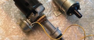
Non-contact ignition system device
The BSZ device for carburetor engines consists of:
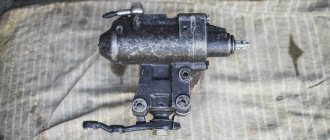
- Distributor. This is a device that is responsible for creating a spark at the right moment. It is also called the ignition system distributor.
- High voltage coil. This element in the ignition system receives low voltage from the battery, converts it and supplies high voltage. Therefore, high-voltage wires come from it. The coil consists of two windings. The primary one is made of a large cross-section wire (connected to the electrical part of the car via the ignition switch relay), the secondary one is made of many turns of thin wire (connected with a high-voltage wire to the distributor).
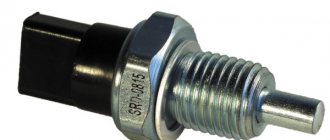
- Switch. This element of the contactless ignition system is responsible for the formation of a spark. In simple words, a switch is a signal amplifier. The switch is only available in the ignition system of internal combustion engines with a carburetor. By the way, SOLEKS is considered the best carburetor. On injection VAZ 2107, as well as on others, a switch is not needed, since its functions are performed by the on-board computer controller.
- High voltage and normal wiring. High voltage wiring must meet heavy insulation requirements.
- Terminals. Serve for connections and must be strong.
Electronic and contactless ignition systems are the same device. It got its name due to the absence of a contact group in the system design. The ignition switch also has a contact group, which is a common cause of engine failure.
Distributor device:
- frame;
- shaft;
- cam;
- moving contact (slider).
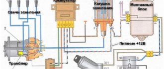
Electronic ignition connection diagrams: VAZ 2101-VAZ 2107
Scheme of a contactless ignition system for VAZ cars:
How contactless ignition works
The sequence and principle of operation of the BSZ is as follows:
- The driver turns the ignition key.
- The circuit is closed and constant voltage from the battery is supplied to the primary winding of the ignition coil. The energized primary winding forms a magnetic field around itself.
- When the starter starts, it begins to rotate the crankshaft of the internal combustion engine and rotates the shaft, which is located inside the distributor along with the slider.
- The hall sensor detects how the distributor shaft rotates (along the protrusion on the shaft) and transmits a signal to the switch.
- The electronic unit turns off the voltage supply to the primary winding based on the signal from the Hall sensor.
- When the voltage supply circuit is interrupted, at that moment a high voltage pulse of up to 24 kilovolts appears in the secondary winding of the coil, which is transmitted through a thick wire to the slider (the moving part of the distributor).
- Fixed contacts are built into the roof. The runner throws an impulse onto one of these stationary contacts. From the contact that received the high voltage pulse, it is transmitted through high-voltage wires to the spark plugs of those cylinders in which the pistons are at top dead centers.
- When voltage is applied to the spark plug, the working combustion chamber of the cylinder already contains fuel and air in a compressed state for ignition.
- The distributor slider rotates to spark all spark plugs according to a certain sequence pattern: 1-3-4-2. Depending on how to install the slider, the entire operation of the system depends, early ignition or later, we learned to determine in another material.
- The car engine starts.
How to set up the ignition on a VAZ 2101 - detailed instructions
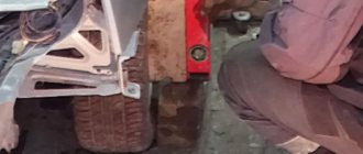
Before starting work, put the car on the parking brake and install wheel chocks under the rear wheels. Remember that during any repair work, these preparatory operations are mandatory from the point of view of ensuring safety precautions, which cannot be ignored.
Next, the VAZ 2101 ignition installation looks like this:
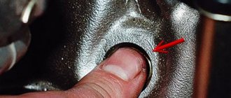
1. Using a spark plug wrench, unscrew the spark plug of the first cylinder of the power unit, and then plug the hole with a suitable plug or finger.
2. Using a special 38mm wrench, rotate the crankshaft until the compression stroke begins in the first cylinder. Evidence of this will be a plug popping out of the spark plug hole. If you closed the hole with your finger, then you should feel quite strong pressure.
3. Rotate the engine crankshaft until the mark on the pulley matches the corresponding mark on the timing cover. If you most often use AI 92 fuel, you should achieve a match with the second risk; if you use gasoline with a lower octane number, use a third (long) line.
4. Carefully unfasten the latches of the plastic distributor cover and remove it:
Removing the distributor cover
5. After cranking the crankshaft, the rotor of the distributor should be positioned so that its outer contact is in the direction of the first cylinder of the engine. In case the direction is incorrect:
- unscrew the distributor mount and, gradually rotating the rotor axis, set it so that its direction is parallel to the engine;
- tighten the fastening nut (do not tighten it completely).
6. Connect a 12 V lamp (voltmeter): connect one wire to the ignition coil terminal (low voltage terminal), and the second to ground.
7. Turn on the ignition and gradually turn the distributor to the right. The distributor should be turned until the connected lamp stops lighting. If the lamp does not light up after turning on the ignition, then the described operation is not necessary.
8. Rotate the distributor to the right and at the moment at which the lamp starts to light, tighten the fastening nut completely.
9. We install the distributor cover.
Installation of contactless ignition for VAZ 2107, 2106
To install the BSZ with your own hands, you will need the following tools:
- Screwdrivers (flat and Phillips);
- Open-end wrenches 8, 10, 13 mm;
- Pliers (pliers);
- Candle key;
- Drill or screwdriver with a drill diameter of 3-3.5 mm. You will have to drill two holes in the body to secure the switch.
- A special wrench for rotating the crankshaft of an internal combustion engine or a regular open-end wrench of 30 mm.
An inspection hole for installing the ignition is not required. Here, in fact, is the procedure for removing the old contact ignition:
- Open the hood, disconnect the battery and disconnect the high-voltage wires from the spark plugs.
- Unscrew the spark plugs.
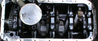
- Rotate the engine crankshaft until the piston in the first cylinder reaches top dead center (TDC). You can use a long screwdriver or wire to check where the piston is located. Make sure that the mark on the engine crankshaft pulley coincides with the very first long mark on the cylinder block.
- Disconnect the latches of the distributor cover and remove it with the wires. Draw a mark on the valve cover opposite the slider.
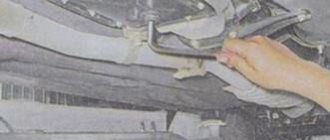
- Disconnect the hose coming from the carburetor and all distributor wires.
- Unscrew the fastening nut and remove the distributor along with the gasket.
- Unscrew the coil mounts (remember which wires are attached where) and remove it.
The procedure for installing contactless electronic ignition on a VAZ 2106-2107.
- Drill and attach the commutator next to the coil. But, do not place it under tanks with liquid.
- Remove the cover of the new distributor and put on the gasket.
- Install into the seat for the distributor so that the moving contact is opposite the drawn mark on the valve cover. Do not immediately tighten the nut all the way.
- Install the new coil where the old one was. The wires from the ignition switch relay, tachometer, and switch must be connected to the reel terminals. The wire from the electronic unit number 1 is connected to the coil terminal marked “K”, the wire from the 4th contact is connected to the coil terminal marked “B”.
- Check the gaps of the spark plugs (should be 0.8-0.9 mm) and screw them in place.
- Snap the distributor cover and connect the high-voltage wires (the central one from the coil and 4 wires to the spark plugs). We connect the wires to the spark plugs strictly in accordance with the designations.
- Connect the vacuum hose.
After installation in the correct sequence, we start the engine and begin setting up the ignition. If after installing a new electronic contactless ignition the engine does not start, you should check the correct connection of the coil wires and the high-voltage wires to the spark plugs. If the wires are normal, then the marks are not aligned.
How to adjust the torque on a VAZ 2101 with your own hands?
After a new lock has been installed as a result of repair or replacement, it is imperative to set up and adjust the advance angle. Without this, the VAZ 2101 engine will not function correctly.
How to install by spark?
To set the ignition on a VAZ 2101 using the simplest method, you need to perform a series of sequential actions:
- The car's engine compartment opens.
- The crankshaft of the power unit is set to the required position according to the marks.
- The central cable is disconnected from the ignition distribution device (distributor). Its contact must be fixed at a distance of about 5 mm from the mass of the car. To do this, you can use the car body or the cylinder head.
- Then the screw that secures the distribution assembly housing is loosened. The ignition is activated.
- The distributor housing rotates clockwise approximately 10-20 degrees.
- After this, it must be turned in the opposite direction. The turning procedure is carried out until a spark appears between the tip of the distributor and the ground. If this happens, the distribution unit is fixed by tightening the bolt.
The “Auto Repair and Maintenance” channel spoke about the nuances of adjusting the ignition angle by spark.
How to adjust the timing using a light bulb?
Before setting up and adjusting the ignition, you need to make sure that the spark plugs are working, otherwise there is no point in carrying out this task.
There should be no carbon deposits on these elements. If it is present, the devices are removed and cleaned; for this you can use an iron brush or special means. Before starting work, you need to find the marks located on the crankshaft, as well as the chain drive pulley, they are cleaned.
The adjustment procedure looks like this:
- First, the crankshaft is rotated so that the mark aligns with the mark on the chain drive housing. If the vehicle is equipped with an engine in which the cylinder diameter is 7.9 cm, then the mark on the shaft must be placed opposite the middle one located on the chain drive. If the size of the cylindrical elements on the car is 7.6 cm, then the mark is aligned with the outermost mark on the cover. This action will allow you to set the engine crankshaft to the top dead center position.
- After aligning the marks, the wire that goes from the ignition coil to the distribution mechanism is disconnected. It must be disconnected directly from the clamp on the distributor. After this, a conductor from a light source is connected to it, which will be used as an adjusting element.
- The other wire from the light bulb is connected to the positive terminal on the battery.
- Using a 13mm wrench, loosen the bolt that secures the distribution unit.
- After this, this mechanism rotates counterclockwise. Then it must be turned in the opposite direction.
- The scrolling procedure is performed until the light source goes out. As a result, the fastening nut on the device body is tightened. The timing gear wire is connected back.
We recommend: Replacing the Nissan Teana timing chain
Adjustment with strobe light
If such a device is available, the configuration can be performed using it.
For this:
- The car engine starts and warms up to operating temperature, this will take approximately 10 minutes. Then the motor stops.
- After this, the vacuum corrector hose is disconnected from the distribution device - it must be plugged. Not all “kopecks” have a regulatory unit, only models released after 1980.
- The strobe contacts are connected to the on-board network of the machine. The connection can be made to the battery terminals. There should be three cables coming from the strobe, two of them are equipped with crocodiles; they are connected to the negative and positive contacts of the battery.
- The remaining conductor from the device must be connected to the “high voltage” of the spark plug installed in the first cylinder. To do this, you need to move its upper part and fix it.
- Using chalk, a mark is made on the metal surface of the cylinder block near the crankshaft pulley. In the diagram below, this is o.
- Then the strobe light is directed to the place where the risk is made, and the power unit starts. If after start-up the mark is in the area where o, then adjustment of the advance angle is not required. If in a different place, then the ignition must be moved back a little. When the engine speed increases, the mark may shift slightly; when this does not happen, it is necessary to check the centrifugal regulator. If the engine is idling, the risk should not move.
- At the final stage, the pipe from the vacuum regulator is connected.
User Pavelmjoy spoke in detail about adjusting the lead angle using a strobe light on classic VAZ models.
Checking the setup results
The diagnostic procedure for the completed task is carried out while driving, while:
- The power unit of the machine starts and warms up to operating temperature.
- On a flat road, you need to accelerate to about 50 km/h, and then move the gearshift lever to the fourth speed position.
- The gas pedal is pressed sharply. For two seconds, detonation (a metallic clatter) may be heard from under the hood, and the speed of the car will quickly increase.
- If such sounds are not heard, then the switchgear must be turned counterclockwise one degree. After this, the diagnostic procedure is repeated. The duration of detonation should be no more than two seconds.
We recommend: Deciphering error codes on Opel Astra
Installation of electronic ignition on video for classic VAZ 2101-2107 cars.
This video covers all the nuances.
How to adjust contactless ignition
Before setting the ignition on VAZ 2101-2107 cars, you need to warm up the engine a little, without letting it stall.
You can adjust either by ear or using a special device called a strobe to set the ignition. A strobe light is a device with which even a beginner can set the ignition correctly. For more information on setting up the ignition with a strobe, watch the video.
How to correctly set the ignition on a VAZ 2101 - check
After completing all the operations described above, it is necessary to check the correctness of the ignition settings. The check looks like this:
- We start the car and move off.
- We accelerate the car to approximately 50 km/h, engage 4th gear and quickly press the accelerator pedal. After this, engine detonation should occur, which should disappear as the car picks up speed.
In a situation where engine detonation appears, but does not disappear as the car accelerates, we can come to the conclusion that early ignition is installed. If detonation does not appear at all, ignition is delayed. The solution to such problems is as follows:
- in the first situation, it is necessary to turn the distributor to the right by about 0.5-1 division;
- in the second situation, it is necessary to turn the distributor to the left by 0.5-1 divisions.
At this point, the question of how to set the ignition on the VAZ 21011 and the progenitor of all classic VAZ models - model 2101, can be considered fully considered.
As you can see, there are no particular difficulties in installing the ignition, and anyone, even a beginner, can handle this work.
Installation of electronic ignition for VAZ 2101, VAZ 2104, VAZ 2105, VAZ 2106, VAZ 2107
Contactless electronic ignition on VAZ 2101, VAZ 2104, VAZ 2105, VAZ 2106, VAZ 2107 cars solves a lot of problems. Today we will talk about how to install contactless electronic ignition on a VAZ 2101, VAZ 2104, VAZ 2105, VAZ 2106, VAZ 2107.
Advantages of electronic ignition
— reliability of electronic ignition;
— convenient operation of electronic ignition;
— improved engine starting in winter.
The advantages of electronic ignition are fully justified. And there is only one step that needs to be overcome, buying an electronic ignition. Yes, this is exactly the problem, since you will have to shell out a lot of money to buy an electronic ignition.
How to choose electronic ignition?
If you buy a contactless electronic ignition as a kit, then I advise you to pay attention to a Russian-made sample (BZS kit for VAZ BSZV-625-01 cars - designed to work in the electrical equipment system of 4-cylinder carburetor engines VAZ 2101, VAZ 2102, VAZ 2103 , VAZ 2104, VAZ2105). This electronic ignition kit has proven itself positively. When choosing an electronic ignition kit, be sure to take into account the difference in the length of the distributor shaft. For VAZ 2101-VAZ 2105 engines they are slightly different from VAZ 2103, VAZ 2106, VAZ 2107 engines.
The electronic ignition kit for VAZ 2101, VAZ 2102, VAZ 2103, VAZ 2104, VAZ 2105, VAZ 2106, VAZ 2107 consists of : an ignition coil, an ignition distributor and wires.
Tools for installing electronic ignition :
— open-end, socket and ring wrenches for 8, 10, 13 and 38 for setting the TDC of the engine.
How to install electronic ignition for VAZ 2101, VAZ 2102, VAZ 2103, VAZ 2104, VAZ 2105, VAZ 2106, VAZ 2107
- Set the engine crankshaft to the top dead center (TDC) mark. A positive result of the installation can be considered the coincidence of the marks on the front engine cover and the crankshaft pulley. The marks are installed by turning the ratchet nut using a 38mm wrench.
2. Remember the correct position of the runner and distributor. This is the position in which you will install the new electronic ignition distributor. On my car, the correct position is when the slider is turned to cylinder 4 relative to the distributor cap.
3. Before removing the ignition coil, remember which wires are attached to the mark (B+). Then we proceed to remove the ignition coil.
4. Remove the distributor lock together with the gasket.
5. Install and secure the switch in its place and connect the minus to ground.
6. Install the ignition coil and secure it to the body. Note the different location of terminals “B” and “K” on the new electronic ignition coil.
7. Connect the wire from the switch to terminal “K”, and the “plus” wire to terminal “B”.
8. Install the distributor, and then connect the switch to the distributor using wires. Check the position of the runner and distributor again, put on the cover and connect the wires to the distributor in the order “1-3-4-2”.
9. After all the work done, you can start the engine and adjust the ignition. Electronic ignition adjustment is carried out by ear, by turning the distributor “in one direction and the other way”, we find the optimal position at which the engine will operate stable.
Ignition system of VAZ 2101 Zhiguli
- Repair manuals
- Repair manual for VAZ 2101 (Zhiguli) 1970-1985.
- Ignition system
5.0 Ignition system Ignition system diagram 1 – generator;
2 – ignition switch; 3 – ignition distributor; 4 – breaker cam; 5 – spark plugs; 6 – ignition coil; 7 – battery Ignition distributor R-125 1 – roller; 2 – oil deflector... 5.1 Setting the ignition timing. Location of marks for setting the ignition 1 – TDC mark. on the crankshaft pulley; 2 – ignition timing mark by 10°; 3 – ignition timing mark by 5°; 4 – 0° ignition timing mark To check the ignition timing there are three marks 2, 3 and 4 on the mechanism cover...
5.2 Gap between breaker contacts in the ignition distributor Checking and adjustment PERFORMANCE ORDER 1. Check the gap between breaker contacts in the following order. 2. Place the gear shift lever in neutral and apply the parking brake to the vehicle. 3. Remove the cover from the ignition distributor...
5.3. Checking ignition devices on a stand (Category). See the list of materials inside...
5.4 Possible ignition malfunctions, their causes and methods of elimination CAUSE REMEDY METHOD The engine does not start Current does not pass through the breaker contacts: – the breaker contacts are dirty, oxidized or burnt; increased gap between contacts - clean the contacts and adjust the gap between them - loosened...
↓ Comments ↓
1. Technical data
1.0 Technical data 1.1 Main overall dimensions of the VAZ-2101 car 1.2 Main overall dimensions of the VAZ-21011 car 1.3 Main overall dimensions of the VAZ-2102 car 1.4 Technical characteristics of the cars 1.5 Controls and monitoring devices 1.6 Ignition switch 1.7 Interior ventilation and heating controls
2. Operation and Maintenance
2.0 Operation and maintenance 2.1. Vehicle operation 2.2. Vehicle maintenance
3. Engine
3.0 Engine 3.1 Features of the device 3.2 Possible engine malfunctions, their causes and methods of elimination 3.3 Removing and installing the engine 3.4 Disassembling the engine 3.5 Assembling the engine 3.6 Bench tests of the engine 3.7 Checking the engine on a car 3.8. Cylinder block 3.9. Pistons and connecting rods 3.10. Crankshaft and flywheel 3.11. Cylinder head and valve mechanism 3.12. Camshaft and its drive 3.13. Cooling system 3.14. Lubrication system
4. Fuel system
4.0 Fuel system 4.1. Power system 4.2. Carburetor
5. Ignition system
5.0 Ignition system 5.1 Setting the ignition timing 5.2 Gap between the breaker contacts in the ignition distributor 5.3. Checking ignition devices on a stand 5.4 Possible ignition malfunctions, their causes and methods of elimination
6. Starting and charging system
6.0 Starting and charging system 6.1. Battery 6.2. Generator 6.3. Starter
7. Transmission
7.0 Transmission 7.1. Clutch 7.2. Gearbox 7.3. Cardan transmission 7.4. Rear axle
8. Chassis
8.0 Chassis 8.1. Front suspension 8.2. Rear suspension 8.3. Shock absorbers 8.4 Possible malfunctions of the chassis, their causes and methods of elimination
9. Steering
9.0 Steering 9.1 Features of the device 9.2. Inspection, check and adjustment of steering 9.3. Steering mechanism 9.4. Steering rods and ball joints 9.5. Pendulum arm bracket 9.6 Possible steering malfunctions
10. Brake system
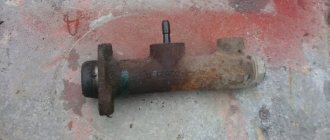
10.0 Brake system 10.1. Features of the device 10.2. Checking and adjusting brakes 10.3. Clutch and brake pedal bracket 10.4. Main cylinder 10.5. Front brakes 10.6. Rear brakes 10.7. Rear brake pressure regulator 10.8. Parking brake 10.9 Possible brake malfunctions, their causes and methods of elimination
11. Electrical equipment
11.0 Electrical equipment 11.1. Electrical circuit diagrams 11.2. Lighting and light signaling 11.3. Sound signals 11.4. Windshield wiper 11.5. Heater electric motor 11.6. Control devices
12. Body
12.0 Body 12.1 Features of the device 12.2. Repair of the body frame 12.3. Paint and varnish coatings 12.4. Anti-corrosion protection of the body 12.5. Doors 12.6. Hood, trunk lid, bumpers 12.7. Body glazing and windshield washer 12.8 Instrument panel 12.8. Removal and installation 12.9. Seats 12.10. Heater
13. Features of repair
13.0 Features of repair 13.1. Car VAZ-21011 13.2 Cars VAZ-21013 13.3. Car VAZ-2102 13.4 Cars VAZ-21021 and VAZ-21023
14. Applications
14.0 Appendices 14.1 Tightening torques for threaded connections 14.2 Tools for repair and maintenance of vehicles 14.3 Used fuels, lubricants and operating fluids 14.4 Basic data for adjustments and control