How to replace the ignition switch on a VAZ 2101-VAZ 2107?
Replacing the ignition switch:
Removal: 1) At the beginning of the operation, remove the upper and lower casing from the steering column. (For information on how to remove the cover, see the article: “Replacing the instrument panel”)
2) Next, using a marker or something else, mark the wires that are connected to the back of the lock, and only then disconnect all the wires.
3) Next, using a Phillips screwdriver, unscrew the two lower screws that secure the ignition switch.
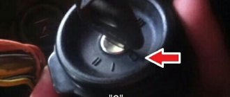
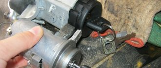
4) Then insert the key into the lock cylinder and turn it to position “0”, thereby disabling the anti-theft device that locks the steering wheel. At the same time, use a thin awl or screwdriver to press the latch that holds the lock in place... (Continued in point 4)
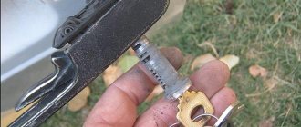
5) And then pull the key to remove the lock from the bracket.
Note! Installing a new lock occurs in the reverse order!
Checking the ignition switch elements for functionality:
1) To check the correct closure of the contacts at different key positions, do the following:
• First, take the voltage from the “AKB - Rechargeable Battery” and the generator and thereby apply it to the contacts in accordance with the table:
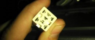
Note! The free “INT” plug, just so you know, is intended only for connecting a radio receiver, and contacts “30/1” and “30” are used to connect wires coming from the battery and generator as mentioned above!
2) Now check how the steering wheel lock works, also known as an anti-theft device, for this:
• Insert the key into the lock and turn it to position “III”, and pay attention to the locking rod (Indicated by the number “1”), which at this moment should extend.
• Then turn the key in the lock to position “0” and again turn your attention to the locking rod, which at this moment should sink.
Note! And also take note that the key must be removed from the lock cylinder only when it is in position “III”!
Replacing the contact part of the lock:
1) First, remove the ignition switch from the car.
Note! In fact, it is possible to remove and install the contact part of the lock even if the ignition switch is installed in its place, but only in this case, replacing the contact part will be much more difficult than with the lock removed!
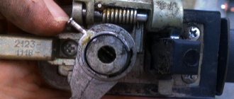
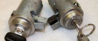
2) Then pry the retaining ring through the hole in the end of the case under the number “2” (see “photo”), and after prying the ring, carefully remove the contact part from the case.
Note! When reinstalling the contact part, install it so that the wide protrusion under the letter “A” in the photo above fits into the wide groove that is present on the lock body. And after installing the contact part, check that the locking rod “under the number 1” is located next to the plugs “15” and “30” on the contact part!
Ignition switch VAZ 2107
Adjusting the carburetor trigger 2105, 2107 ozone
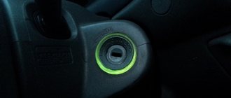
The ignition switch (IZ) of the VAZ 2107 is an electromechanical type device. It is located under the dashboard and is attached to a bracket welded to the left side of the steering column shaft.
Purpose of the ignition switch
The main function of the protection system is to synchronize electrical systems when starting and operating the vehicle. When you turn the key in the lock, current begins to flow to the starter solenoid relay, to the ignition system, to instrumentation and lighting devices, heater, etc. When the ignition switch is turned off, most of the electrical equipment is completely de-energized, protecting the battery from discharge. At the same time, the anti-theft mechanism is activated, blocking the steering wheel at the slightest turn.
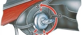
The key in the ZZ VAZ 2107 can occupy four positions, three of which are fixed:
- 0 — “Disabled.” Electrical wiring is de-energized. The key cannot be removed from the lock; the anti-theft mechanism is disabled.
- I - “Ignition”. The engine spark system, generator excitation, instrumentation, exterior lighting, windshield wiper blades, heater and turn signals are included. The key cannot be removed from the lock; the anti-theft mechanism is disabled.
- II - “Starter”. Current is supplied to the starter. The position of the key is not fixed, so it must be forcibly held in this position. It cannot be removed from the lock.
- III - "Parking". Everything is turned off except the sound signal, side lights, windshield wiper blades and interior heating stove. When the key is removed from the lock, the anti-theft mechanism is activated. When turning the steering wheel in any direction, it will be locked. To confirm the locking, a sound signal will be heard - a click. To disable the anti-theft system, you need to insert the key into the lock, set it to position “0” and smoothly turn the steering wheel in any direction until it unlocks.
When descending a Zhiguli from a mountain or driving at neutral speed, you must not turn off the engine and remove the key from the lock. Such actions will lead to jamming of the steering wheel and the creation of an emergency situation on the road due to difficulties in controlling the car.
Ignition switch connection diagram
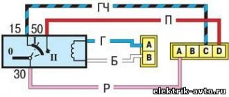
On the new VAZ 2107, all the wires going to the ignition switch are collected into one plastic chip, which is not difficult to connect. To disable the lock, you simply need to remove this chip. If the wires are placed on the contacts separately, the connection should be made according to the following scheme:
- the red wire (starter) is connected to pin 50;
- to pin 15 - double blue wire with a black stripe (ignition, heater, instruments on the front panel, heated rear window);
- to pin 30 - pink wire (battery plus);
- to pin 30/1 - brown wire (battery plus);
- to the INT contact - black wire (dimensions, rear brake lights and headlights).
The ignition switch of the VAZ 2107 is connected according to a scheme that is universal for all classic VAZ models.
Ignition switch device
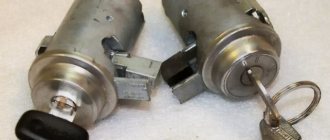
The VAZ 2107 ignition switch is a cylindrical body that contains a cylinder and a contact mechanism, with a protrusion for fixing the steering wheel. At one end of the cylinder there is a recess for a key, at the other there are contacts for connecting electrical wiring. Each key is individual, which provides an additional guarantee against theft. The lock consists of two parts connected by a leash. In the upper part there is a cylinder (locking device), in the lower part there is a contact group.
The lock
The ignition switch has two tasks:
- the main one is rotation of the movable disk of the contact device;
- additional - steering wheel lock when the ignition is off.
The locking is carried out using a movable locking pin, which, when turning the key clockwise, is partially retracted inside the lock body. When the key is rotated in the opposite direction, the finger extends, and when the key is pulled out, the finger fits into a special recess in the steering column. At the same time, a loud click is heard.
To turn, use a leash that:
- ensures rotation of the movable disk of the contact mechanism;
- fixes the lock in the desired position using holes, balls and springs.
Ignition switch contact mechanism
The contact group of the lock consists of two parts:
- movable disk with conductive plates;
- a fixed plastic block in which electrical wiring contacts are fixed, having special protrusions at the point of contact with the movable disk.
When the key is turned, the plates on the disk close or open the necessary contacts on the block, turning on or off the corresponding components and mechanisms.
Exactly three switched contacts
One line through which current is supplied, and only one ignition circuit - this solution is typical for all VAZ cars, if we talk about the “2110”, “2170” and later families. Even in Grants, produced since 2012, the additional ignition circuit did not appear. In general, with the transition to the “Ten” family, three “significant” terminals of the lock remained:
- Contact "30";
- Terminal “15” (can be designated as “15/1”);
- Terminal "50".
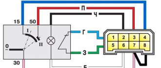
The ignition switch circuit looks trivial, even if we talk about the Lada 2110.
The Tens connector has 8 terminals. And in Priora, as well as in Grant and Kalina, this number is reduced to three (Fig. 2).
Of the 8 terminals available in the VAZ-2110 connector, the 7th and 8th simply duplicate each other. Two more are connected to the button, and another pair of terminals are connected to the lamp.
The lock connector of all VAZ models, starting from “2170”, is equipped with only three contact terminals. And the additional connector, which is equipped with a pair of terminals, is connected to the immobilizer in these cars.
The “3” mark has disappeared from the “Tens” lock cylinder. And until now, VAZ produces just such locks, where the key can be installed in one of the following positions:
- "Turned off";
- "Ignition";
- "Start".
The presence of the “Parking” mode, as you can see, is not provided here.
How to remove the lock
Be sure to remove the negative terminal from the battery. Some car enthusiasts do not do this, explaining this by low circuit voltage. However, if the wires short out during repair work, this will lead to malfunction of some electrical equipment elements. Turn the key to the zero position. This will make it easier to dismantle the device due to the fact that the steering wheel holding shaft will fit slightly into the secret part. Remove the steering column cover. To do this, unscrew the five screws connecting the top and bottom of the casing
Pull the upper part of the casing up, acting very carefully. We remove and put away all the elements of the casing. Having removed the casing, unscrew the screws that secure the lock itself.
There are two of these screws, they are located below the switch.
Disconnect the wires from the lock.
In order not to break the latch during dismantling, we find a small gap on the left side of the bracket. We insert an awl or a thin nail into it and press the latch.
Use a slotted screwdriver to remove the mechanism from the bracket.
Another important tip: mark how the wires were connected. This will help you avoid any confusion when installing a new device.
Installing the "Start" button
Some car enthusiasts install a separate button in the car in a convenient place to start the engine. It is connected to the starter circuit by breaking the red wire going to terminal 50 on the ignition switch. The car is started as follows:
- The key is inserted into the ignition switch.
- The key is turned to position "I".
- Pressing the button turns on the starter.
- After the engine starts, the button is released.
In this case, you can turn off the engine only by turning the key in the opposite direction.
In order for the button to turn off the engine, it must be connected according to a slightly modified circuit
In order to use a button to stop the motor, that is, to turn it into a “Start-Stop” button, you need to use two additional relays:
- headlight relay RS 711;
- starter relay 113.3747–10 or 90.3747–10.
When you press the button, current from the battery goes to the headlight relay, closing its contacts, and then to the starter. When the engine starts, the button is released, opening the contacts of the starter relay and breaking its circuit. However, the positive wire remains connected through the headlight relay for some time. When you press the button again, the headlight relay contacts open, breaking the ignition circuit, and the engine stops. To delay the activation of the starter, an additional transistor is included in the circuit.
Thus, even a novice car enthusiast can replace the ignition switch of a VAZ 2107. To do this, you need a minimum set of tools and following the recommendations of specialists
Particular attention should be paid to the correct connection of wires to the lock contacts
Creating and installing ignition switch lighting
The most balanced option for arranging the backlight is a design assembled from LEDs - this is a “cheap and cheerful” option. To assemble a general LED lighting circuit, you will need a minimum of knowledge and the ability to work with a soldering iron.
There are several ways to implement the backlit idea. The simplest of them is to use double-sided tape, with which several diodes are attached to the ignition switch. This design option is unreliable, since after some time the diodes may simply fall off. In addition, from a visual point of view, diodes mounted on adhesive tape do not look very attractive.
The second method looks a little better. To implement it, it is necessary to drill a certain number of holes in the ignition switch housing. Selected diodes are installed in these holes. To provide them with power, the positive terminals are connected to the anodes of the diodes and the power terminal, through which energy is supplied to standard devices.
The negative contacts (cathodes) in this case are connected to the corresponding terminal connected to the car body. The installed LEDs will turn on in parallel with the side lighting, and to adjust their brightness you need to add an additional resistor to the circuit.
There is also a third way to install the backlight, which results in the highest quality and most attractive design - installing an ignition switch ring light. This method differs from the previous ones in complexity and the need to adhere to the following operating algorithm:
- The first step is to remove the steering column trim and dismantle the lock. As a result, you can easily reach all the necessary points.
- Next, a resistor is soldered to the LEDs. The resistor value is selected depending on the operating voltage of the LEDs (for 10-volt LEDs, a 1 kOhm resistor is suitable).
- A ring with a diameter slightly larger than the diameter of the ignition switch is cut out of a sheet of plexiglass. Using a thin drill, several holes are made in the ring, in which LEDs will later be installed. When working with thin plexiglass, LEDs should be reinforced with silicone or glue.
- Instead of individual diodes, you can take an LED strip. In this case, there is no need to drill holes in the ring - one small hole in the lock body will be enough, through which the tape will be fixed.
- After assembling the structure, it must be checked for functionality. It is not recommended to install the ignition switch right away: first you should make sure the functionality of the backlight and adjust it so that the lighting is uniform.
- If everything is assembled correctly and works, then all elements are reassembled. Since the work involves electrical equipment, all wires must be properly insulated.
For example, there is an alternative scheme for creating an ignition switch illumination, which requires a cut off wide neck of a plastic bottle. There will be no difference in the process of installing the lighting, except that during preparation the neck will have to be stretched using heat.
A little theory
The ignition switch must switch, that is, connect contacts that supply power to different electrical circuits. The voltage from the battery is supplied to the “30th” contact of the lock, and sometimes two lines are used: “30/1” and “30/2”. Each line is equipped with a 30 Ampere fuse, hence the well-established name.
When turning the key, the "30 pins" are usually connected to the following:
- In the “Parking” position - to the “INT” contact, from which current is supplied to additional equipment;
- “Ignition” - to the “INT” contact, also to contacts “15/1” and “15/2”;
- “Start” - to contact “15/1”, but not to “15/2”, as well as to contact “50”.
From terminal “50” power goes to the starter solenoid relay. The “15th” contact, in turn, feeds the main ignition circuit. And if there is an additional circuit, it will be open when the starter operates.
Let us note once again: when the key is set to the “Start” position, contact “15/2” does not receive a positive potential. This is true for all cars of any model, including the VAZ Nine.
Ignition switch circuit
- Battery
- Starter
- Generator
- Relay in mounting block
- Egnition lock
- Start relay
The electrical wiring connected to the mechanism works according to the following scheme:
There are four lock positions.
Zero position. With it, all electrical networks are turned off, except for two terminals, indicated in the diagram in dark color.
First position. Dimensions, windshield wipers, and heater fan receive power.
Second position. Additionally, power is supplied to the ignition system, indicators and buttons on the dashboard, turn signals and starter.
Third position. Only the dimensions, windshield wipers and horn continue to receive power.
The lock mechanism interacts with several electrical circuits that combine the vehicle's electrical appliances into a single circuit. When we turn the key, voltage from the negative terminal of the battery is supplied to the ignition coil.
Since the lock mechanism is regularly used by the driver, some of its elements wear out and fail. Sometimes all you need to do is spray the lock cylinder with WD-40. However, the effect may not last long and repair work will still be required in the near future.
The ignition switch is designed as follows:
The simplest thing is to replace the faulty lock with a new one. The cost of this part for the VAZ 2106 car is low. The replacement must begin with the process of removing the old mechanism.
Ignition switch malfunction
Electrical equipment is a rather fragile car system, consisting of many components and causing known troubles to many motorists.
Even a single disconnected contact can create a lot of problems. And the situation when a vehicle does not start at all is familiar to almost every driver and always makes one nervous. One of the reasons for the domestic car VAZ 2104 in the above situation may be a faulty ignition switch, if, for example, the contacts are burnt. In addition, it must be replaced in such trivial cases when the key is lost or broken, and, indeed, the ignition switch mechanism itself is not particularly reliable. The damaged mechanism is not capable of performing its direct function as a breaker - closing contacts and, accordingly, transmitting a “command” to start the engine.
Malfunctions
The design of the lock is quite simple and reliable, but the lock may well break. There are only two malfunctions that can happen to this element: mechanical and electrical.
A mechanical failure includes a problem with the secretion. Due to debris that gets inside the secretion and moisture, corrosion is formed, which prevents the movement of moving elements inside the secretion. As a result, the lock begins to jam when you turn the key, jams, or stops rotating altogether. This problem can be eliminated by pouring WD-40 or at least brake fluid inside. However, if it is possible to restore the functionality of the secret in this way, it will not be for long. The secret itself is not repairable, and in the event of such a malfunction, the VAZ-2101 ignition switch will eventually need to be replaced.
An electrical fault is the burning of the nickels of the contact group. Because of this, there will be no or insufficient contact between the runner and the nickel. Electrical appliances on the car will not work, and there may be no power supply to the starter. If the burning was minor, then you can try to restore the functionality of the lock by cleaning the nickels with a diamond file, followed by wiping with alcohol or gasoline. But if the nickels are badly burnt, then you will need to either change the contact group or the lock assembly.
Ignition Switch Removal Tools
The ignition switch on the “four” is located on the left side of the steering wheel under the vehicle’s instrument panel. It is fixed to the bracket that holds the steering mechanism. Usually, in order to replace the ignition switch, you need a simple tool. Two screwdrivers are quite suitable for these purposes. One is a cross, the other is as small as possible. Instead of the latter, it is quite possible to use an awl. And, of course, do not forget to purchase a new, working lock from the auto store.
Removing and installing the lock
Removing this element from the car is quite simple and all you need is a Phillips screwdriver and a thin flat-head screwdriver or an awl. Before starting work, be sure to disconnect the negative terminal from the battery.
To get to the fastening of this element, you will first need to unscrew the bolts securing the lower facing panel of the steering column, and then remove it.
Removing the ignition switch
Afterwards, you need to unscrew the two bolts securing the lock, which hold it in its seat. In the same seat there is a small technological hole. By inserting a thin screwdriver into this hole, you need to press the latch that holds the lock, and then push it out of its seat.
Only then disconnect all the wires. On some models, the wiring going to the lock is collected in a chip that is put on the contacts of the lock. This feature will greatly facilitate the installation of a new element, since such a VAZ-2101 ignition switch does not require a wiring diagram.
How to remove the lock
| Remove the two screws securing the ignition switch (bottom view). | Insert the key into the ignition switch, turn it to position “0” (turning off the anti-theft device), press the lock with a screwdriver through the hole in the bracket and... |
| ...remove the switch from the bracket and the key from the switch. | Label (or remember the connection order) the wires and terminals of the ignition switch. Disconnect the wires from the switch. |
But there are also versions of the car in which the wiring is directly connected to the contacts, and when installing a new element with this type of wiring connection on a VAZ-2101, an ignition switch circuit will be required.
If the lock assembly is replaced, then you can connect the wiring to the new one, install it in place, secure it and cover it with a decorative panel.
If only the contact group is changed, then the removed lock is disassembled. The contact group is fixed using a locking ring, which must be pryed off with an awl or screwdriver and removed. After this you can remove the group. A new one is installed in its place and secured with the same retaining ring. After this, everything is put in place and the VAZ-2101 ignition switch is connected.
How to repair a car
The ignition switch is referred to in some sources as the ignition switch.
The procedure for connecting high-voltage wires
|
Reasons for replacing the ignition switch on a VAZ 2101, VAZ 2104, VAZ 2105, VAZ 2106, VAZ 2107, VAZ 2109, VAZ 2110, VAZ 2114 :
· The ignition switch is broken (the ignition key gets jammed when turning, the key turns with difficulty or does not turn at all). In this case, some experts advise spraying WD-40 , but, as a rule, this does not give much result, and if it does, it is a temporary result, then all that remains is to replace the ignition switch. Although there are exceptions.
· The contact group has burned out (this means the contacts on the chip, it happens that they burn out) In this case, difficulties arise in starting the starter.
How to check the contact group of the ignition switch?
| System design car ignition
|
It is better to carry out this type of check with an assistant. To check the contact group of the ignition switch, you should use a “control”. We connect one end of the “control” to the battery negative, and the other to the starter solenoid relay. Well, as mentioned earlier in the article, you will need the help of a friend to turn the ignition key all the way. And at this time, keep an eye on the “control” lamp, which should light up. If the lamp does not light up, therefore, the command from the ignition switch is not given. This indicates that the contact group needs to be replaced, but many motorists prefer to replace the ignition switch assembly.
But it doesn’t matter whether your ignition switch or its contact group is broken, you will still have to remove the ignition switch
Ignition switch removal tool:
· Screwdrivers (phillips and small);
Surprisingly, this is all the tool you need to replace the ignition switch on a VAZ 2101, VAZ 2104, VAZ 2105, VAZ 2106, VAZ 2107, VAZ 2109, VAZ 2110, VAZ 2114.
Which ignition switch should I buy?
Every motorist thinks about their quality before purchasing spare parts. The quality of the ignition switch depends on the manufacturer. If you need to buy an ignition switch, I can recommend leading manufacturers DAAZ, the Auto-Garant company. In short, we go to the car market and ask the seller for an ignition switch or contact group made in Russia. Don’t be fooled by a cheap product; it’s better to overpay 10 rubles than to suffer later.
How to replace the ignition switch on a VAZ 2101, VAZ 2104, VAZ 2105, VAZ 2106, VAZ 2107, VAZ 2109, VAZ 2110, VAZ 2114.
· Remove the negative terminal from the battery;
· Fix the ignition key in the zero position.
· Remove the steering column cover (by unscrewing 5 screws).
· Remove the ignition switch (by unscrewing the 2 fastening screws).
· Use a thin screwdriver to press the latch and pull out the ignition switch towards you.
· Remove the chip and wires from the ignition switch.
· We change the lock to a new one, rearrange the wires to the new ignition switch.
How to replace the ignition switch contact group on a VAZ 2101, VAZ 2104, VAZ 2105, VAZ 2106, VAZ 2107, VAZ 2109, VAZ 2110, VAZ 2114.
We carry out the same operations as when replacing the ignition switch, only after removing it, pry off the retaining ring and remove the contact group and the rod on the ignition switch secret.
After this, it is enough to simply connect the wires to the ignition switch correctly using the VAZ ignition switch connection diagram.
After this, all that remains is to correctly connect the wires to the ignition switch.
Wiring diagram for the ignition switch of VAZ 2101, VAZ 2104, VAZ 2105, VAZ 2106, VAZ 2107, VAZ 2109, VAZ 2110, VAZ 2114.
| Ignition system malfunctions car
|
Central lock installation
So, the doors of your car close no louder than in a foreign car, but you have to lock them separately with a lock. To simplify this point, let's move on to installing the central lock. In addition to the fact that this option will make driving your car even more convenient, it will to some extent protect your car from theft.
Installing a central lock on a VAZ will allow you to close and open the doors by pressing the key fob button, turning the keys in the driver's door lock, or from a special button on the instrument panel, if you wish to install one.
Installation of the mechanism
First, we remove the trim from all the doors and the panels that are located between them, and we also dismantle the lower protective curb of the rear doors.
Now we need to drill holes in all the doors to mount the motors
Please note that if you plan to protect the wires with special rubber tubes, then the holes you will make for the wiring will need to be slightly wider.
Important! Before you start drawing wires, disconnect the negative terminal of the battery!
Important! Before you start drawing wires, disconnect the negative terminal of the battery!
When installing motors on doors, do not forget that three of them have two terminals, and one has four. It is mounted on the driver's door.
Having stretched all the wires to the central unit and connected this entire system to the battery, you can install the door trim and panels in place. Check the entire system in operation. When connected to the battery, the locks should work immediately, so keep the keys in your hands or do not leave the car. If the circuit does not work correctly, there is a possibility that the plus and minus were mixed up when installing the wiring.
And, of course, do not forget that you can connect both the alarm and the trunk lock to the central locking of your car, thereby making it also automatic.
Using the ignition switch of a Kalina car
Most passenger cars are equipped with a device for turning the ignition system on and off. How to use the Kalina ignition switch?
How to remove the ignition switch: advice from professionals
The Kalina ignition switch (image No. 1) sometimes has to be removed from the car for various reasons. On the Lada Kalina, the reasons for these actions may be: complete failure of the lock, the need to replace the APS coil or the lock contact group. To perform this you need a minimum set of tools:
- chisel with good sharpening;
- hammer;
- flat-head screwdriver;
- pliers.
The work is performed in a certain order:
- you need to disconnect the negative terminal from the battery;
- remove the switches located under the steering wheel;
- using a small sharp chisel and pliers, unscrew the bolts securing the Kalina switching mechanism;
- remove the released bracket and the ignition switch from the steering column;
- Use a screwdriver to pry up the clamp with the wires going to the APS coil and disconnect it from the unit;
- disconnect the contact block from the common wiring harness.
- The steering column cover can be removed by unscrewing 7 screws using a Phillips screwdriver: 2 on the left side, 2 on the right, 3 on the bottom. Then you need to pull down the adjustment lever and lower the column. Both halves of the casing can be easily removed.
- To remove the steering column switches, simply squeeze the clamps and remove them from their landing spots.
- The bolts for securing the Kalina lock usually come with the head cut off during tightening. Therefore, they are unscrewed with a small chisel, applying light tangential blows. Once the bolts have moved, they can be removed using small pliers. It is better to tighten the lock with bolts with internal hexagon heads, which can be purchased in specialized stores. Such fasteners have an M6 thread, the length of the bolts is 20 mm.
- To remove the ignition switch, lightly pull the electrical wiring harness and release the connectors under the housing.
- Before installing the lock in its place, you need to insert the key into it and move it to position 1. The steering lock latch will go inside the lock. After this, you should check the functionality of the steering lock system. If everything works fine, continue installing and securing the lock and wires. If the steering shaft does not lock after a full rotation of the steering wheel, it is necessary to adjust the installation position of the ignition switch on the steering column so that the lock latch can fit into the groove located on the shaft.
- There are situations when a standard key is difficult to insert into the lock hole. In this case, you can spray WD-40 into the key hole and insert and remove the key several times. If WD-40 is not available, you can use semi-synthetic oil, which only requires one drop.
Rules for using the lock
The standard ignition switch of the Lada Kalina car has 3 standard ignition key positions.
- Position 0 is fixed. The ignition key can be removed from this position. In this position, external lighting devices can operate, including fog lights, illuminating the road ahead of the car. The hazard warning system works, you can use high and low beams, and turn on the audio system.
- Position 1 is fixed. The key cannot be removed from this position. The ignition is on. In this case, electrical power is supplied to all energy consumers of the vehicle, with the exception of the starter. Leaving the key in this position for a long time can drain the battery. Before turning on the starter, it is recommended to hold the key in this position for several seconds. During these seconds, the electric fuel pump will create the required pressure in the fuel system, which will greatly facilitate starting the engine, especially when it is cold.
- Position 2—turn on the starter. The key does not lock in this position. When released, it returns to position 1.
Do not hold the key in the starter position for more than 10 seconds. If the engine does not start, you need to take a break for 10-15 seconds and try again. Do not hold the key in this position while the engine is running. While Kalina’s car is moving, it is prohibited to remove the key from the lock. If you do this, steering failure will occur due to locking of the steering column and a sharp deterioration in the functioning of the braking system.
“Classics”, as well as the “Ninth” family
Fiat engineers, when developing the ignition switch for their 124 model, used two supply lines (“30” and “30/1”). The ignition line was the only one.
Another ignition circuit containing contact “15/2” was added during the transition to the “2109” family. It, in turn, is switched using a relay. In different families, only the diagram differs, but not the “behavior” of the car when the key is installed opposite the marks:
- Position 0: everything is off;
- Label 1: ignition and engine operation;
- Mark 2: starting the starter;
- Label 3: “Parking” mode.
To turn off the engine, turn the key to position “0”. The spark plugs lose spark and the engine stops.
The ignition switch module, if we talk about the “classic family”, is equipped with 5 terminals (see Fig. 2). Starting from the “2109” family, this solution is not used. Several wires come out of the lock cylinder and are connected to a remote connector.
The connector layout can be easily identified using the color coding (see diagram above). When carrying out any installation work, remember the following: you must turn off the engine, open the hood and disconnect one of the battery terminals. Usually the negative one is turned off.
Occurring faults
The design of the lock is quite simple and reliable, but the lock may well break. There are only two malfunctions that can happen to this element: mechanical and electrical.
A mechanical failure includes a problem with the secretion. Due to debris that gets inside the secretion and moisture, corrosion is formed, which prevents the movement of moving elements inside the secretion. As a result, the lock begins to jam when you turn the key, jams, or stops rotating altogether. This problem can be eliminated by pouring WD-40 or at least brake fluid inside. However, if it is possible to restore the functionality of the secret in this way, it will not be for long. The secret itself is not repairable, and in the event of such a malfunction, the VAZ-2101 ignition switch will eventually need to be replaced.
An electrical fault is the burning of the nickels of the contact group. Because of this, there will be no or insufficient contact between the runner and the nickel. Electrical appliances on the car will not work, and there may be no power supply to the starter. If the burning was minor, then you can try to restore the functionality of the lock by cleaning the nickels with a diamond file, followed by wiping with alcohol or gasoline. But if the nickels are badly burnt, then you will need to either change the contact group or the lock assembly.
An interesting article about biofuel produced from ordinary sawdust, read more here.
Malfunctions of the VAZ 2101 ignition switch and their symptoms
The ignition switch may fail due to the breakdown of one of its component parts. Such malfunctions include:
- breakage of the cylinder (wear of pins, weakening of their springs, wear of pin sockets);
- wear, mechanical damage to the locking rod or its spring;
- oxidation, burning, wear or mechanical damage to contacts, contact terminals.
Breakage of the larva
A sign that it is the cylinder that has broken is the inability to insert the key into the ignition lock or turn it to the desired position. Sometimes the cylinder fails when a key is inserted into it. Then, on the contrary, difficulties arise with its extraction. In such cases, you should not use force in an attempt to restore the lock's functionality. This can break the key, and instead of replacing one part of the device, you will have to change the entire lock.
If the key does not turn or cannot be removed from the lock, the cylinder is most likely broken
Lock rod malfunction
The locking rod itself is difficult to break, but if you apply enough force and jerk the steering wheel while the shaft is locked, it can break. And it is not a fact that the steering shaft will begin to rotate freely. So if the lock breaks while the steering wheel is fixed, under no circumstances should you try to resolve the issue by force. It's better to spend a little time, disassemble it and fix it.
It may also happen that due to wear of the rod or weakening of its spring, the steering shaft will no longer be fixed in position “III”. Such a breakdown is not critical, except that it will become a little easier to steal the car.
The locking rod may also break
Contact group malfunction
Problems with a group of contacts occur quite often. Typically, the cause of its malfunction is burning, oxidation or wear of the contacts themselves, as well as their terminals to which the wires are connected. Signs that the contact group has failed are:
- no signs of operation of instrumentation, lighting lamps, light alarms, heater fan motors and windshield washer when the key is in position “I”;
- lack of starter response when moving the key to position “II”;
- constant supply of voltage to the vehicle’s on-board network regardless of the key position (the ignition does not turn off).
There are two ways to deal with such malfunctions: repairing the contact group, or replacing it. If the contacts are simply oxidized or slightly burnt, they can be cleaned, after which the lock will work normally again. If they are completely burnt out, or worn out so much that they cannot perform their functions, the contact group must be replaced.
If the contacts are burnt or slightly oxidized, they can be cleaned
Causes of ignition switch failure
In the seventh VAZ model, the ignition switch consists of two main parts:
- mechanical, where the key is inserted;
- contact group to which the wires are connected.
Most often, the mechanical part of the lock requires replacement after an attempted theft or jamming. If you lose your keys, you will also need to purchase a new “secret”. A malfunction of the contact group occurs due to a short circuit, insulation failure or oxidation of the contacts. Every car enthusiast should know how the ignition switch works, be able to disassemble and diagnose the malfunction of this unit. If you understand the connection diagram and the design of the spare part, you can quickly fix the problem even on the road. Repairs do not require special skills or professional tools.
When is replacement necessary?
It is quite easy to identify mechanical problems. You just need to externally inspect the part for cracks or deformation. If jamming or sudden jumps occur when the key is rotated, the mechanism needs to be replaced. Diagnostics of the contact group requires a control device that will show the presence of voltage on the starter when the ignition is on. If there is no such device, you can use a regular “control” - a light bulb with two outgoing wires. If when you turn the key all the way, the lamp does not light up, it means that the signal is not being received and the contact group is not working. Therefore, the mechanism needs to be changed.
Advice! If one of the ignition switch parts breaks down, it is better to purchase the entire set at once, since some manufacturers may have different connecting connectors for the components.
We purchase the necessary materials
To ensure that the doors of your car no longer close with a roar and grinding noise, we will install silent locks on it. To do this, we purchase the necessary kit in the amount of two pieces. Each box has two locks.
Well, the second set that we need is a central locking kit. The universal kit traditionally includes four motors, a control unit, all the necessary wires and several strips.
After purchasing the main components of the upcoming work, we prepare the necessary tools:
- Drill and various drills;
- Hammer;
- Screwdrivers, Phillips and hexagonal, screwdriver;
- Additional wires;
- Protective tubes for wiring;
- Well, and some other little things: a knife, glue, alcohol, etc.
We install silent locks
The first stage of the work is the installation of new and dismantling of old locks. To ensure that you do not have to remove the door trim, this process must be performed carefully and carefully.
To begin, unscrew the bolts one at a time so as not to drop the internal lock. In the same way, screw on the new silent ones in reverse order.
The second point is to replace the old bolt that holds your lock with a new one.
We apply this scheme to all remaining doors. Having completed the installation, we perform a check. If any problems arise, for example, the door does not close well, then try to push the lock deeper. Although, by choosing the option of silent locks without a “flag”, such situations should not arise.
