Contactless distributor
How to easily check the hall sensor on your own: tools and instructions
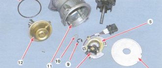
The distributor device, operating with an electronic ignition mechanism, is similar to the design of a mechanical distributor. This device also has a slider, a plate with a bearing, a vacuum corrector and a centrifugal regulator. However, the contact group and capacitor are replaced by a Hall sensor and a metal screen fixed on the shaft.
The contactless distributor in the 2106th model works as follows:
- A permanent magnet and Hall sensor are located on the moving section. A screen with slits rotates between them.
- As soon as the magnet field is blocked by the screen, the voltage is zero at the terminals and the sensor is inactive.
- When the roller rotates and overcomes the slot, the magnet field reaches the sensor surface. In turn, a voltage is generated at the output of the element, which is sent to the electronic unit (switch). The latter sends a signal to the coil, which generates a discharge going to the ignition slider.
The non-contact dispenser is more durable in operation. The bearing and Hall sensor fail less often due to the lack of mechanical stress.
Operating principle of the distributor
Contactless ignition on a VAZ 2106 car
In many ways, the operating principle of the distributor remained unchanged for many years. In VAZ cars, such as VAZ 2109, 2106, 2107, 2108, an ignition system of this type was used almost until the end of the last century.
The basis of the work is the connection of the distributor with the engine crankshaft. When the piston in the first cylinder takes the position corresponding to TDC, the breaker contacts open, a high voltage appears in the ignition coil, directed through a slider located in the distributor cover to the spark plug of the first cylinder.
There the combustion of the fuel assembly occurs, and the crankshaft continues to rotate. In addition to moving the pistons, it causes the breaker cam to rotate. When in another cylinder another piston occupies a position corresponding to TDC, at this moment the breaker contacts in the distributor open again, and a high-voltage voltage is generated in the ignition coil and supplied to the desired spark plug.
This joint rotation of the crankshaft, the breaker cam and the distributor slider ensures that a spark appears where and when needed. However, this does not cover all aspects of how the distributor works. To understand its operation, it is necessary to touch upon such concepts as the angle of the closed state of contacts (UZSK) and the ignition timing angle (IAF)
UZSK
A concept such as UZSK characterizes the time when the breaker contacts are closed. In essence, this is an indirect characteristic of the accumulation of energy in the coil after the completion of spark formation. UZSK directly affects the amount of energy spent on sparking and, accordingly, on engine operation.
In cases where the distance between the contacts is small, the coil will not accumulate the necessary energy and the spark energy will be low, which will lead to interruptions in the operation of the motor. A large gap also leads to interruptions, since the contact breaking time is reduced and the coil does not have time to fully discharge.
Each ignition system has its own optimal UZSK, to ensure which, if necessary, the distributor must be checked and adjusted.
UOZ
This concept concerns the moment of ignition of a fuel assembly. The fact is that its combustion does not occur instantly, and often, to ensure optimal conditions for such a process, it must begin earlier than the piston reaches the TDC position. The OZ characterizes the time by which the appearance of a spark precedes the appearance of the piston in the TDC position.
It is constantly changing, and its value completely depends on the operation of the motor under specific conditions, i.e. depending on the load, vehicle speed, quality and type of fuel used. To ensure optimal combustion of the fuel assembly, the distributor contains a centrifugal regulator and is also connected to a vacuum regulator.
VACUUM REGULATOR
It is this device that can change the OZ if necessary. As soon as the motor load changes, appropriate adjustments are made to the operation of the distributor device parts.
Important! The load is determined using the throttle valve.
The vacuum regulator of the distributor is a closed cavity. To ensure better performance, the design is divided by a diaphragm. One cavity goes directly to the carburetor.
When a vacuum occurs, the diaphragm begins to move. As a result, pressure is exerted on the movable disk and the breaker cam. The response time of the latter is adjusted depending on the current situation.
Attention! The distributor changes the moment of spark formation, thereby affecting the performance characteristics of the motor.
OCTANE-CORRECTOR
This is a very important element in the distributor design. Without it, the entire system could not function normally. The unit changes the SOP depending on the fuel that is currently being used.
By its design, this distributor element resembles two plates with an arrow. The same arrow is installed on the engine. There are special lines on it, through which the ignition angle is adjusted. It is almost impossible to do without this part when refueling different types of gasoline.
CONTACTLESS SYSTEMS
Technologies do not stand still. Every year, the automotive world is rocked by new innovations. This is precisely what innovation became in its time, supplementing the distributor design with switches.
Attention! In switches, the signal is supplied to the control electronic module, and not to the coil.
The second name for non-contact systems in the distributor device is Hall sensors. The simple design of these devices ensures uninterrupted signal supply. The sensors themselves work due to changes in the magnetic field.
Distributor malfunctions
The following signs indicate that the distributor is malfunctioning:
When there is a spark on the central wire, but not on the spark plug wires, this indicates a breakdown of the slider.
- the car jerks periodically when driving;
- Unstable engine operation at idle;
- the engine does not start at all;
- the knocking of the piston fingers is heard while accelerating;
- the speed increase dynamics decreased;
- fuel consumption has increased.
In most cases, the causes of distributor failure are:
Breakdown of the roof and ignition coil occurs due to large gaps in the contacts of the distributor cover and slider, spark plugs and bad candlesticks.
- burnout of the runner;
- oxidation or shorting of contacts under the cover;
- breakdown of the distributor cover;
- failure of one of the sensors;
- problems with the shaft bearing and other problems.
We recommend: Review of the best diesel engine oils
In each of these cases, replacement is required. But at the same time, for almost any car, it is possible to change not the entire distributor, but only its failed part, which is an advantage, since it significantly reduces the cost of repairs.
Often, problems in the operation of the contact distributor appear due to changes in the gaps in the contacts or their contamination, so it is necessary to check after 10 thousand km.
The most basic check of the distributor is a visual assessment of the condition of the slider, contacts and cover.
In a contactless distributor, the main malfunction is the failure of the hall sensor or inductive sensor.
To check the ignition system and distributor, among other things, observe the spark on the unscrewed spark plug after starting the engine. In garage conditions, you can also check using measuring instruments or indicators.
The distributor capacitor is also one of the parts that often fail. It helps to increase the voltage supplied to the spark plugs when the engine starts. And in order to check it, you need to disconnect it and touch the “ground”, and if a characteristic crackling sound is heard and a voltage drop is observed, the capacitor is working, if this does not happen to the replacement part.
A distributor is always a dismountable unit that can be disconnected, removed from the car, disassembled into components, a problem can be detected and eliminated by replacing the damaged part.
The device of the ignition system of the VAZ 2106
How to install the ignition on a VAZ-2106: detailed instructions with photos
The ignition system (IS) of a gasoline engine is designed to create and timely supply pulse voltage to the spark plugs.
Composition of the ignition system
The VAZ 2106 engine is equipped with a battery-contact ignition system.
VAZ 2106 cars are equipped with a battery-contact ignition system
The ignition system includes:
- accumulator battery;
- switch (ignition switch with a group of contacts);
- double-winding transforming coil;
- distributor (distributor with contact-type breaker and capacitor);
- high voltage wires;
- candles.
The ignition includes low and high voltage circuits. Low voltage circuits include:
- battery;
- switch;
- primary winding of the coil (low voltage);
- breaker with spark arresting capacitor.
The high voltage circuit includes:
- secondary winding of the coil (high voltage);
- distributor;
- spark plug;
- high voltage wires.
Purpose of the main elements of the ignition system
Each SZ element is a separate unit and performs strictly defined functions.
Accumulator battery
The battery is designed not only to ensure the operation of the starter, but also to power the low voltage circuit when starting the power unit. During engine operation, voltage is supplied to the circuit not from the battery, but from the generator.
The battery is designed to start the starter and supply power to the low voltage circuit
Switch
The switch is designed to close (open) contacts of a low-voltage circuit. When you turn the ignition key in the lock, power is supplied (cut off) to the engine.
The ignition switch closes (opens) the low voltage circuit by turning the key
Ignition coil
The coil (bobbin) is a step-up two-winding transformer. It increases the voltage of the on-board network to several tens of thousands of volts.
With the help of an ignition coil, the voltage of the on-board network is increased to several tens of thousands of volts
Distributor (distributor)
The distributor is used to distribute the pulse voltage coming from the high-voltage winding of the coil to the rotor of the device along the contacts of the top cover. This distribution is carried out by means of a slider having external contact and located on the rotor.
The distributor is designed to distribute voltage across the engine cylinders
Breaker
The breaker is part of the distributor and is designed to create electrical impulses in a low-voltage circuit. Its design is based on two contacts - stationary and movable. The latter is driven by a cam located on the distributor shaft.
The breaker design is based on moving and stationary contacts
chopper capacitor
The capacitor prevents the formation of a spark (arc) at the breaker contacts if they are in the open position. One of its outputs is connected to the moving contact, the other to the stationary one.
The capacitor prevents sparking between the open contacts of the breaker
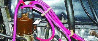
High voltage wires
Using high-voltage wires, voltage is supplied from the terminals of the distributor cover to the spark plugs. All wires have the same design. Each of them consists of a conductive core, insulation and special caps that protect the contact connection.
High-voltage wires transmit voltage from the contacts of the distributor cap to the spark plugs
Spark plug
The VAZ 2106 engine has four cylinders, each of which has one spark plug. The main function of spark plugs is to create a powerful spark that can, at a certain moment, ignite the combustible mixture in the cylinder.
Spark plugs serve to ignite the fuel-air mixture
When you turn the ignition key, current begins to flow through the low-voltage circuit. It passes through the contacts of the breaker and enters the primary winding of the coil, where due to inductance its strength increases to a certain value. When the breaker contacts open, the current instantly drops to zero. As a result, an electromotive force arises in the high-voltage winding, increasing the voltage tens of thousands of times. At the moment such a pulse is given, the distributor rotor, moving in a circle, transmits voltage to one of the contacts of the distributor cover, from which voltage is supplied to the spark plug through a high-voltage wire.
Design and principle of operation of a typical ignition system
Ignition system components
On the technical side, the ignition system is part of the engine electrical equipment complex. Structurally, it consists of the following elements:
- Battery or other power source. It supplies a low voltage of 12 volts to the network.
- Switch. When you turn the key, the switch closes and low voltage flows into the energy storage device.
- Energy storage. There are two types: inductive (a transformer-type ignition coil that converts low voltage into high voltage up to 30 thousand volts) and capacitive (capacitor).
- Energy storage and distribution control unit. Depending on the type of ignition system, this may be a chopper, a transistor switch, or an ECU (electronic control unit).
- Distributor. This unit can be mechanical or electronic. It supplies certain candles with energy at a given point in time.
- High voltage circuit wires. They supply high voltage to the electrodes of the spark plugs.
- Spark plug.
The operation of the ignition system is based on the following principle: when low-voltage voltage is supplied to the network, energy is accumulated and converted, which is then distributed among the spark plugs, on the electrodes of which a spark is formed, provoking the ignition of the air-fuel mixture.
Tuning on carburetor modifications of the VAZ 2107
All old textbooks on servicing classic Zhiguli models describe a method for setting the moment of spark formation using a light bulb, although experienced motorists can easily do without it. You will understand why this happens as you read this material, but for beginners it will be useful to familiarize yourself with the old proven technique.
In order to check the performance of the carburetor or adjust its operation, it is recommended to read the following material: https://vazweb.ru/desyatka/dvigatel/remont-karbyuratora-vaz-2107.html
To correctly set the ignition of the “seven”, you need to ensure that the following conditions are met simultaneously:
- the notch on the crankshaft pulley is opposite the long mark on the timing cover;
- in this case, the round mark marked on the camshaft chain drive gear coincides with the boss on its body;
- the piston of the 4th cylinder has completed the compression stroke and is at top dead center;
- the contacts inside the distributor are open;
- The movable contact of the slider faces the fixed contact on the distributor cover, where the wire from the spark plug of the 4th cylinder is connected.
Note. On non-contact systems, at this moment the Hall sensor sends a signal to the switch to break the low voltage electrical circuit, which leads to the appearance of a high voltage pulse on the wire leading to the spark plug of the 4th cylinder.
The light bulb is used to control the ignition timing, for which it must be connected with one wire to the “K” contact of the high-voltage coil, and with the second to the vehicle ground. You should know that at the same moment the piston of the first cylinder is also in the TDC position, only there the air-fuel mixture is not compressed, but exhaust gases are released after its combustion. This is why ignorant car enthusiasts often confuse the first cylinder with the fourth when installing the ignition.
When the above actions occur simultaneously, a spark discharge occurs on the electrodes of the spark plug of the 4th cylinder, as evidenced by the flash of the connected light bulb. To achieve these conditions and set the ignition correctly, follow the instructions:
- Turn the crankshaft with a 36 mm wrench, aligning the notch on the pulley with the long notch on the timing cover.
- If at this moment the engine valve cover is removed, then it is better to navigate by the mark on the camshaft gear, placing it opposite the housing boss.
- Take the ignition distributor, remove the cover and turn its shaft to place the slider opposite the wire leading to cylinder No. 4 (there are cylinder number markings on the cover). Insert the distributor into the engine hole, holding the slider and housing in this position, and then secure it with a 13 mm wrench nut.
- Connect the light bulb wires and turn on the ignition by turning the key. Loosen the nut securing the distributor and slowly turn it by the housing until the lamp flashes, indicating the moment of sparking. Reattach the distributor.
- Turn off the ignition and make sure that the contacts inside the distributor are currently open. Take a 0.35 mm feeler gauge and check the gap between them, if necessary, adjust it by loosening the fastening screws with a screwdriver.
Note. The instructions imply that before starting work the distributor was removed from the engine without aligning the marks.
The ignition is considered to be set correctly if, after installing the distributor cap and connecting the wires, you manage to start the engine, and then you need to adjust the timing. The non-contact system is installed in the same way, with the exception of checking the gap in the contact group due to its absence.
Instructions for replacing the timing chain in a VAZ 2107 car are presented here: https://vazweb.ru/desyatka/dvigatel/zamena-tsepi-grm-na-vaz-2107.html
Important point. In most cases, the ignition is set without removing the valve cover, which is why the position of the mark on the gear is not visible. You have done everything according to the instructions, but the engine does not start. This means that a spark is supplied to the 4th cylinder during the exhaust stroke, and compression at this moment occurs in the first cylinder. The problem can be solved simply:
- remove the distributor cover;
- unscrew the nut securing it;
- pull the distributor out of the socket, turn the slider exactly 180° and insert the element back;
- Press the distributor skirt with the nut and install the cover.
Advice. If the engine does not start after these steps, but begins to show signs of life, then the problem lies not in the ignition setting, but in a malfunction of one of the system elements.
Checking the ignition timing of the VAZ-2107 engine
The methods described below make it possible to independently adjust the ignition timing. They are suitable equally well for both contact and non-contact distributors.
We adjust the ignition timing at idle speed. We warm up the engine to operating temperature, at idle speed, turning the body relative to the block, “catch” the position in which the speed will be the highest. We fix the distributor in this position.
We check the correct setting of the ignition timing “on the fly”. Having looked at a free section of a flat road, we drive out onto it. We keep the speed at 40 km/h in fourth gear and sharply press the gas pedal. a loud metallic knock should be heard under the hood, disappearing by itself after a few (four to six) seconds. Is everything exactly like this for you? This means the adjustment is complete. If the knocking does not go away for a long time, we stop, loosen the distributor and turn the distributor clockwise a couple of millimeters, making the ignition later. We start the engine again, accelerate, and repeat the test.
If there is no knocking at all, then the distributor needs to be turned counterclockwise, setting the ignition “early” and checked again while driving. After doing these steps several times, you get the optimal ignition timing specifically for your VAZ engine.
Still have questions? Watch this video
Didn't find the information you are looking for? on our forum.
Diagnostics and testing of the ignition coil of a VAZ 2106
How to check the ignition coil of a VAZ-2106 car at home? The best way is to use a multimeter or ohmmeter. Winding testing using this equipment is carried out as follows:
- to make sure that the primary winding is in good condition, connect an ohmmeter to its side terminals and look at the resistance readings. For a fully working ignition coil, it should be at least 3-4 ohms. Otherwise, the device will need to be repaired or replaced;
- to check the secondary winding, one of the ohmmeter outputs is connected to the same side one, and the second one is connected to the central terminal on the pulse transformer itself. The normal value is somewhere in the range of 7.5-9.2 ohms. To get accurate data, it is better to consult your vehicle's owner's manual. If there are any deviations, the ignition coil must be replaced.
Before performing the checks described above, you must disconnect the negative terminal from the battery. This will help eliminate the risk of short circuit
Diagnostics and testing of the ignition coil of a VAZ 2106
Checking for spark
Checking the spark is possible using several methods: to ground, using a multimeter, or a special tester on a piezoelectric element. The first method is the simplest. The body of the unscrewed spark plug is brought to the metal (usually the engine cylinder block), after which the engine is cranked by the starter and the presence of a spark is analyzed.
Please note that this verification method cannot be used when diagnosing injection cars. The fact is that a car with an injector has an ECU and other electrical equipment that is quite sensitive and can be damaged
The photo shows checking the spark plug on a VAZ 2106
The second method allows you to better assess the condition of the spark plug, identify breakdown, etc. The use of a special tester is a method of checking the spark on injector cars, reminiscent in its principle of checking by analyzing the spark breakdown to ground (the first method). In this case, the risk of burning the control unit is minimized. Now let's talk about how to check the spark on a fuel-injected engine.
Checking the secondary winding
The secondary winding of the coil is checked in almost the same way, only one of the ohmmeter wires needs to be connected to the side terminal, and the second to the central one on the coil. Everything is demonstrated below:
Here the resistance data is completely different and during normal operation it should be in the region of 7.4-9.2 kOhm. Judging by the readings of the device, my case shows and confirms again that everything is fine with the coil.
The photo shows a check of the secondary winding of the ignition coil of a VAZ 2106
To avoid any misunderstandings, I want to warn you that the figures given in this article apply to a greater extent to VAZ 2106 type B117-A ignition coils, although on many models the parameters are identical. But still, for your modification, it is better to look at the data in specialized sources.
If, as a result of the check, it turns out that the element is faulty, then it is necessary to replace it with a new one.
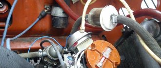
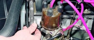
Checking the distributor
If the coil is working properly, but the engine does not start, the problem must be looked for in the distributor; to do this, you need to remove its top cover by unfastening 2 latches. The inside of the cover must be carefully inspected; all contacts and the ember must be intact. You need to remove the slider from the distributor and also inspect it from the inside; it happens that it cracks and a spark hits ground.
Photo: Checking the VAZ 2106 distributor
Next, you need to carefully inspect the breaker contacts and, if necessary, clean them with fine sandpaper. You also need to inspect the capacitor, which is usually screwed to the distributor; without it, there will be no spark either. To test the capacitor, you need to apply power to it from the battery, and then connect a light bulb or short-circuit the contacts with a metal object. If the light does not blink and there is no spark when it closes, the capacitor is faulty. It can be replaced by any other, but not polar.
In conclusion, I would like to note the fact that you should never check the spark for the gap from the wire to the engine; in this case, the ignition coil quickly fails and the VAZ 2106 will no longer be able to start without replacing it. All this happens because the coil is punctured from the inside, and all because of the very large gap for breakdown.
Diagnostics of the distributor runner
The slider is replaced if this element can no longer perform its functions. You may need a multimeter for diagnosis.
How to check the slider at home, several options:
- The multimeter probes must be installed in the place where the slider itself is connected to the coal at the point of breakdown. To identify a breakdown, you need to carefully look at the device - the spark will go either completely to the side, or only partially. But it should be borne in mind that a breakdown cannot always be determined.
- Another diagnostic option is to test the device using a central cable type. You will only need to dismantle the cover itself, then bring the high-voltage cable from the reel to the distributor, then try to start the engine. When cranking the starter, if the distributor is broken, the spark will start to jump. If there is no slippage, then you don’t need to look for the cause of the problem here.
- If there is a crack on the runner, the spark will go to the side. In the event that the resistance of the element is completely burned out, but an attempt to restore the conductor could occur. In turn, this could lead to electrical breakdown of the element and its complete failure. In this case, it must be completely replaced.
After the repair, the distributor is adjusted. The adjusted mechanism is put in place; during installation, it is important to correctly match the marks and connect the high-voltage cables. The procedure for adjusting the ignition as a whole may differ depending on the vehicle, and there may be several adjustment options.
Loading …
Removal and installation of the ignition distributor of the VAZ 2106 distributor
The ignition distributor (distributor) is removed from the VAZ 2106 car for repair or replacement. The engine of the VAZ 2106 model has a distributor of type 30.3706.
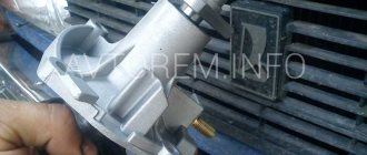
To distinguish it from distributors of other models, a mark (ring groove) is made on the shank. To remove the distributor from a VAZ 2106 car you will need: a spark plug wrench, a bit, two “7” keys, a “13” wrench, and a screwdriver. 1. Remove the tip from the spark plug of the first cylinder and unscrew it.
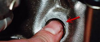
2. Close the spark plug hole with your finger.
3. Turn the crankshaft until the compression stroke begins in the 1st cylinder (air will begin to escape through the spark plug hole). Then, while continuing to turn the crankshaft, align mark d on the crankshaft pulley (highlighted with chalk) with the middle mark b (if you are using gasoline with an octane rating of 92 or 95) or the extended mark c (if you are using gasoline with an octane rating lower than 92). Reinstall the spark plug of cylinder 1 and connect the high-voltage wire to it.
4. Disconnect the hose from the vacuum ignition timing regulator. 5. Remove the high-voltage wires from the sockets of the distributor cover.
6. Unscrew the nut securing the distributor, remove the spring washer and plate. 7. Remove the distributor from the engine.
8. Turn over the distributor and, holding the lower nut, unscrew the nut securing the low voltage wire; remove the washer and wire. 9. Unfasten the holders and remove the cover from the new distributor.
WARNING
Before installing a new distributor on a VAZ 2106 car, check and, if necessary, adjust the gap between the contacts of the breaker.
10. Install high-voltage wires into the cover of the new distributor in accordance with the operating order of the engine cylinders.
NOTESThe operating order of the engine cylinders is: 1-3-4-2. The distributor rotor rotates clockwise. Cylinder numbers are marked on the distributor cap and on the engine cylinder head.
11. Connect the low-voltage wire to the new distributor.
12. Turn the rotor of the new distributor to a position in which its outer contact (shown by the arrow) will be directed towards the contact of the 1st cylinder on the distributor cover. NOTE
When the outer contact 2 of the rotor coincides with mark a on the cover, it simultaneously coincides with the head of screw 1 on the distributor body.
13. While holding the distributor shaft from turning, insert it into the socket on the cylinder block so...
14... so that the line passing through the spring latches is approximately parallel to the axis of the motor. 15. Secure the distributor in this position to the cylinder block without completely tightening the nut. Connect the hose to the vacuum regulator. 16. After installing the distributor on a VAZ 2106 car, check and, if necessary, adjust the ignition timing (see “Checking and adjusting the ignition timing”).
Checking the ignition system on a VAZ 2106 car
| WARNING The VAZ 2106 is equipped with a contact ignition system. A voltage of approximately 24,000 V is supplied to the high-voltage wires (as an option, a contactless high-energy ignition system can be installed on a VAZ 2106 car - a voltage of approximately 40,000 V). At low current levels, this voltage is not life-threatening, but can lead to electrical injury. Therefore, if you handle a high-voltage wire with the ignition on, use a thick rubber glove or, as a last resort, pliers with insulated handles. |
To check the ignition system on a VAZ 2106 car, you will need: slotted and Phillips screwdrivers, pliers with insulated handles and a tester or 12 V test lamp with two wires connected to it. You can also use a car portable lamp.
RECOMMENDATIONS Before checking the ignition system, place the gear shift lever in neutral and leave the parking brake on.
1. With the ignition off on the car, check the integrity and fit of the high-voltage wires in the ignition distributor cover, as well as the fit of the high-voltage wire in the ignition coil. 2. Check the wires going to the ignition coil and their connections. Also check the wire connecting the distributor and the ignition coil.
3. Turn on the ignition on the VAZ 2106 car. Check if current is supplied to the ignition system. Connect one wire of the tester or warning lamp to the “+B” terminal of the ignition coil, and the other to ground. If no current is supplied to the ignition system, then the fault is in the ignition switch or in the wiring from the switch to the ignition coil. In order to get to the nearest car service center, you can apply emergency power to the ignition system. To do this, connect the “+B” terminal of the ignition coil and the “+” terminal of the battery with an additional wire. Fasten the wires securely. Keep in mind that now, in order to turn off the engine, you will need to disconnect the additional wire from the “+” terminal of the battery.
Symptoms of a problem
Before you begin repairing the mechanism being analyzed or the distributor cover, naturally, you should carefully check it. This will help you find out the specific cause of the problem and how to deal with it.
There are certain signs that indicate a malfunction in the distributor. Their list included the following:
- While driving, the car jerks unusually and abnormally.
- The engine will not start.
- As the engine accelerates, the piston pins begin to knock.
- The car picks up speed very slowly.
- Fuel consumption increases significantly.
Naturally, the presence of any of the above symptoms does not yet give the right to say that the problem lies specifically in the ignition distributor. But if any of them is identified, you should begin to “sound the alarm” and, preferably, prepare to repair the distributor.
The list of the most common distributor malfunctions includes:
- A runner who went broke.
- Burnt contacts that are located in the distributor cover.
- Hall sensor failure.
- The Hall sensor bearing is stuck or loose.
- The appearance of cracks in the lid.
- The Hall sensor plug has poor contact.
- Oil gets into the distributor despite the presence of a protective cap.
As a rule, if the distributor slider is in order, then the car engine starts the first time, without any problems. But when difficulties are observed with the plant, this indicates a damaged or broken rotor (provided that the problem is not elsewhere).
Breakdown of the distributor slider
The most common malfunction of the distributor slider is its breakdown. It can be external or internal. Obviously, the external one is determined by noticeable signs - a black mark, the internal one must be checked by the presence of a spark (details below).
The breakdown occurs due to metallization of the channel. For preventive purposes, metallization should be checked regularly. This is done using a multimeter or other similar device. The channel is checked for moment of resistance. The probes of the device are connected to the place of the slider where there is doubt about breakdown.
Purpose of the mechanism
Before we tell you how a faulty distributor should be checked to identify breakdowns, let’s look at the purpose of the device. The breaker is a unit designed to detect the moment of formation of high-voltage signals in the system. The distributor is installed on both carburetors and injectors, and this mechanism is used to distribute electric ignition among the engine cylinders. That is why many car owners are interested in the question of how to set the ignition and adjust the distributor, where to turn it - this is necessary for the normal operation of the power unit.
In its design, this mechanism differs from others in the presence of various elements in the structure, which tend to wear out over time. When the first signs of malfunctions in the operation of the distributor are identified, the device must be removed and repaired, since its condition largely determines the operation of the power unit and its characteristics.
In addition to setting the ignition, the distributor performs the following functions:
- interrupts the primary ignition circuit, which ensures the appearance of a high-voltage pulse;
- distributes the spark among the cylinder spark plugs in a certain sequence.
Breaker device design
What is ignition timing?
For the ignition to work correctly, the following condition must be met: sparking must occur at the moment when the piston is at TDC. This should be a compression stroke. This moment should be the flash point.
| Options | Units | Classical | Contactless |
| Spark energy | mJ | 20 | 60 |
| Secondary voltage rise time from 2 to 15 kV | mks | 30 | 20 |
| Secondary voltage max | kV | 26 | 29,5 |
| Spark duration | ms | 1,5 | 2 |
However, that's not all. The time it takes for the fuel mixture to completely burn must also be taken into account. Therefore, the spark plugs must create an impulse with some advance, which is called the advance angle. As a result, the mixture reaches the peak of combustion, and the cylinder begins to move downward.
If sparking occurs earlier, then such ignition is called earlier, and if late, then later. Early leads to detonation. This is why the engine quickly overheats and becomes inefficient, although fuel consumption can sometimes be greatly reduced. This can be determined by the spark plug electrodes, which are covered with a white coating. With late ignition, power is noticeably lost, and black smoke comes out of the exhaust pipe, which indicates that gasoline, without having time to burn in the cylinder, burns out in the exhaust system.
The spark plugs, in this case, turn black. Popping noises in the exhaust pipe can also tell this. Late ignition means that the spark plugs are simply flooded with fuel, which does not burn or burns incompletely. When they are flooded, they do not work.
Electronic ignition system (microprocessor ignition system)
Electronic ignition system
Pros and cons of contactless ignition
| Pros + | Minuses - |
| Current is supplied to the ignition coils through a semiconductor switch to the primary winding, this makes the spark energy much greater due to the higher voltage on the secondary winding of the ignition coil (up to 10 kV). | The most significant disadvantage of this ignition system is its low reliability compared to others. The well-known switches that were initially installed on these systems were characterized by very low reliability and often failed. |
| Functionally replacing the CG, an electromagnetic pulse shaper made using a Hall sensor and which, compared to the CG, provides a significantly better pulse shape, as well as stability, throughout the entire engine speed range. In this regard, an engine equipped with BSZ produces significantly better power indicators and allows significant savings on fuel (up to 1 liter per 100 km). | If any problems arise, you will not be able to do without new spare parts. |
| A significant advantage of this ignition system is the low need for frequent adjustments and maintenance compared to KSZ. But as for servicing the system, everything is simple and comes down to lubricating the distributor shaft every 10 thousand km. mileage |
Pros and cons of contact ignition
| Pros + | Minuses - |
| This is the simplest ignition system, it can be repaired in an open field using a spool and a match within 10 minutes; this number will not work with a contactless number. Failure of the contact ignition system is unlikely. | Current is supplied to the primary winding of the ignition coil through a contact group. In connection with this, there is a significant limitation on the voltage on the secondary winding of the coil (up to 1.5 kV), which means there is strong spark formation. |
| Maintenance is required frequently. It is necessary to constantly monitor the gap in the CG, the angle of the closed state of the CG. It is necessary to constantly clean the KG contacts because they burn during operation. Also, the distributor shaft needs to be lubricated every ten thousand kilometers. It is also recommended to lubricate the distributor cam. | |
| The reliability of this system is low; it often breaks down and requires constant maintenance. |
| Pros + | Minuses - |
| A significant advantage of the MPSZ is that it provides high-quality ignition control depending on the crankshaft speed, pressure in the intake manifold, engine temperature, and carburetor throttle position. There is no mechanics in the system, so this ignition system produces a spark perfectly, the sparking is very powerful. | Cannot be repaired in the field. Difficult to find spare parts. Low reliability. |
Instructions for connecting short circuit
To carry out the operation of removing and replacing the short circuit, you need to prepare:
- heads or keys for “8” and “10”;
- extension;
- small wrench or ratchet.
The short circuit is located in the left corner of the engine compartment.
The replacement procedure consists of the following steps:
- First, remove the central high-voltage wire from the ignition distributor (distributor).
- Next, you need to use the key set to “8” to disconnect the supply wires from the short-circuit contacts. To correctly connect the wires after installing a new unit, it is better to remember how they are connected or mark them.
- At the next stage, you need to unscrew the two nuts securing the clamp that holds the short circuit housing.
- After unscrewing the clamp nuts, you can remove the coil.
- Next, a new product is installed, all wires are connected according to the marks.
Assembly is carried out in reverse order.
Repair of VAZ 2109 distributor
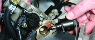
One of the most common problems with the VAZ 2109 distributor is failure of the Hall sensor. If the sensor is faulty, the engine stops starting; we replace this part as follows:
- remove the distributor from the engine;
- unscrew the cover (two screws);
- dismantle the vacuum regulator;
- unscrew the screw holding the sensor connecting block;
- unscrew the fasteners of the upper bearing holder, it is secured with two screws;
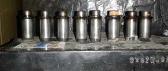
- remove the bearing assembly with the sensor, remove the Hall sensor from the holder (two screws);
- we install a new part, assemble the distributor, and put it in place.
After repairing the VAZ2109 distributor, you may need to adjust the ignition; it is done very simply:
- loosen the three nuts of the PR housing itself;
- with the engine running, gradually turn the distributor in one direction or the other, apply gas with the throttle - we find the position in which the engine picks up speed faster, without dips;
- Then we tighten the nuts and check the car while driving. If it was not possible to find the desired position immediately, repeat the operation.
Types of faults
As a rule, if the distributor slider is in order, then the car engine starts the first time, without any problems. But when difficulties are observed with the plant, this indicates a damaged or broken rotor (provided that the problem is not elsewhere).
The most common malfunction of the distributor slider is its breakdown. It can be external or internal. Obviously, the external one is determined by noticeable signs - a black mark, the internal one must be checked by the presence of a spark (details below).
The breakdown occurs due to metallization of the channel. For preventive purposes, metallization should be checked regularly. This is done using a multimeter or other similar device. The channel is checked for moment of resistance. The probes of the device are connected to the place of the slider where there is doubt about breakdown.
A little theory.
The ignition coil on cars is necessary to convert a low voltage current of 12 V into a high current - 11-20 kV, which is necessary to create a spark at the spark plugs. What happens next is probably known to everyone!? The spark ignites the working mixture and a release of energy occurs, which sets the pistons in motion. As I said in my previous articles, the ignition coil is a kind of transformer, which can also be called a miniature automotive “substation”.
On the “seven”, as a rule, contact ignition systems of the B-117 A type are used. The coil itself is located in the engine compartment and is attached to the left mudguard with two studs. Also found on the VAZ 2107 are non-contact ignition systems (BSZ), in this case, coils of type 27.3705 are used, oil-filled with an open magnetic circuit, as well as type 3122.3705 dry coils with a closed magnetic circuit.