An experienced motorist knows the value of correctly setting the initial ignition timing, as well as the proper operation of ignition timing regulators such as vacuum and centrifugal. If the ignition timing is set incorrectly (and a deviation of even 2-3° can play a significant role), this can lead to increased fuel consumption, loss of power and overheating of the engine, and even shorten its service life. Therefore, for every driver it is very valuable to be able to check and adjust the ignition system, although these processes are quite complex. But if the car owner has decided to implement these operations, then the first thing he should arm himself with is a strobe light for installing the ignition, which is designed to simplify the process of servicing the described system.
>How to properly connect a car strobe light?
Everyone knows that not only the stable operation of the entire engine, but also fuel consumption depends on how correctly your ignition timing is set.
In order to install a car strobe light not on LEDs, but one that is intended for installing the ignition and installing the UOS, you should start the engine at idle and begin to illuminate the special installation marks with the strobe light.
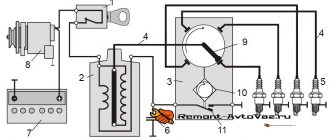
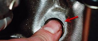
One of them is movable, that is, located either on the crankshaft, or on the flywheel, or on the generator drive pulley, the other is located on the engine body itself.
The capacitive sensor must be attached to the high-voltage wire of the spark plug of the first cylinder so that the flashes are synchronized with the moments of spark formation in the spark plug. Thanks to the light from the flashes, both marks can be seen. If they are located one against the other, it means that the ignition timing is set ideally; if there are small offsets, the position of the distributor-distributor should be adjusted until the marks coincide.
Now let's take a closer look at the procedure for tuning a car engine using a strobe light.
Then, turn off the engine. When connecting the device to the battery, use clamps and be sure to observe the polarity(!). Incorrect connection of the contact wires will lead to a short circuit! Carefully read the instructions supplied with the device in order to avoid this.
In order to form a capacitive coupling with the device, it is necessary to attach the signal cable connected to the spark plugs of the first cylinder to the wire.
Arrange the wires so that they do not get caught in any rotating parts of the machine.
Locate the white mark on the crankshaft pulley or flywheel. After this, identify the same marking on the power unit housing.
Don't forget to follow safety regulations. First, remove all metal objects from yourself, and then set the gear shift lever to neutral.
Wear dielectric gloves. Avoid all possible contacts of body parts and clothing items with moving mechanisms. Start the car and let it run until the idle speed stabilizes.
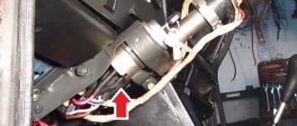
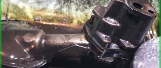
Loosen the mounting bolt that prevents the distributor from turning.
Next, take a strobe light and point its lamp at the crankshaft pulley. This way you can illuminate the mark on the housing and the mark on the engine.
Slowly turn the distributor body; you are required to achieve maximum coincidence of the marks, as we said above. If the marks match, turn off the engine and turn off the strobe. By tightening the mounting bolt, secure the distributor body.
Well, now, you can start testing the car and checking the correct ignition adjustment. To do this, you will need to accelerate the car on a flat section of the road to 50 km/h, and then sharply press the gas. If you hear detonation knocks that last no more than two seconds, you can be sure that you did everything right and deserve a rest.
List of required parts
Before you go to the store to purchase all the parts described below, you should carefully study all the materials and parts present in the garage; it is quite likely that most of them have been collecting dust on the shelves for a long time without any particular need. If you find most of the elements stored among waste materials for the manufacture of the device, the final cost of a finished and perfectly functioning strobe light will not exceed 100 rubles, which will save money for other needs. The first thing you need is a simple, cheap Chinese-made flashlight. It will be better if it is LED. If the available model turns out to be a lamp model, you will need to additionally purchase or remove all the required LEDs from the old flashlight.
In addition to the body, you will need electronic filling, the creation of which requires the following elements:
- transistor type KT315, which is probably stored in a discarded Soviet-style radio;
- thyristor KU112A, it can be found in the power supply of an old TV;
- capacitor designed for voltage 16 V;
- diode with low frequencies;
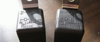
- relay for 12 V voltage, but you should choose a small part that can fit in the flashlight body;
- several "crocodiles";
- a coil of wires, 0.5 meters of which must be shielded;
- a small piece of copper wire.
https://youtube.com/watch?v=BI8F8hIPwLs
Despite the wide variety of circuits created for the correct sequential assembly of the device, the newly minted creator of the strobe will in any case need such a supply of spare parts. In addition to having all the described parts, you need to arm yourself with a soldering iron; it will be better if the car owner has at least minimal skills in using it.
To assemble this device, you need to connect all the parts in series with the existing wires and solder them securely. Through the rear hole in the flashlight, you will have to pass all the necessary wires that will ensure uninterrupted power supply to the strobe. If the selected flashlight model does not have a side hole, the car owner must make it himself. This is necessary in order to bring out a shielded wire, at the ends of which copper wire will be soldered to the central core. It is this element of the created device that will be a special signaling sensor.
tosha3692 › Blog › Adjusting the ignition using a strobe light
So, if we have the main tool for working with the ignition, let's start checking and adjusting.
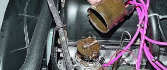
Any ignition distributor (“distributor”) has two correction systems - a centrifugal corrector and a vacuum one. During engine operation, the ignition timing constantly changes depending on the number of revolutions and load, this is necessary to optimize the combustion process of the fuel mixture, and optimally, this means economical and powerful...
Our “strobe light” will help us check the functionality of the correction systems. Let's begin...
1 - the engine is warmed up, the “choke” is removed, the idle speed is adjusted to normal or slightly lower, the vacuum tube running from the carburetor to the “vacuum manifold” of the distributor is removed. In this mode, we check and adjust the setting of the initial ignition timing. ("classic" - from 2 to 7 degrees, depending on the engine displacement; 08 - 010 - 1100cm - 6 degrees, 1300cm - 1 degree, 1500cm - 4 degrees. More details in the car description ).
2 - When the engine speed increases, to approximately 2 thousand, the advance angle should increase by 5 - 7 degrees, if this does not happen, then the centrifugal regulator does not work for us. The main reason is jamming of the centrifugal mechanism, most often due to oxidation. Repair - disassembly, cleaning, lubrication. In addition, the springs of the mechanism often break.
3 — Checking the operation of the vacuum ignition timing regulator is a little more complicated, since its operation is related to the operation of the carburetor. The main condition for the normal operation of the vacuum corrector is that when the engine is running at idle speed, there should be no vacuum in the tube going from the carburetor to the “vacuum manifold”. A vacuum should appear only when the engine speed increases. The timeliness of the appearance of vacuum in the tube can be checked by applying the tip of the tongue to it (to the end of the tube that we removed at the beginning of the procedure from the “vacuum end” of the distributor). If the carburetor does not ensure the timely appearance of vacuum in the tube, then normal operation of the vacuum corrector is impossible, even with a fully functional distributor mechanism.
If there is a timely vacuum, that is, if the carburetor is working correctly, we proceed to check the functionality of the vacuum regulator itself. We connect the vacuum tube back to the distributor and again “shine the strobe light” on the mark. As the speed increases, the mark should “go” even higher, twice as much as it “went” with the tube disconnected. The total advance angle is the sum of three values - the initial ignition advance angle, plus additional advance created by the centrifugal regulator, plus additional. ahead of the "vacuum man". The total angle can reach 30 degrees, depending on the operating mode of the engine, its model and the characteristics of the distributor.
Ignition distributors have certain, specified operating characteristics; their exact parameters and their compliance with the standard can only be determined on special stands. In our case, we can only determine whether this or that system works at all or not. An experienced master, of course, can “by eye” quite accurately determine the correctness of the operating characteristics of the distributor and correct them, but this requires many years of practical work.
And lastly, if one of the ignition timing correction systems or both do not work, then the car’s acceleration dynamics are noticeably lost, “dips” may appear, and gasoline consumption increases.
Source
What is a strobe and why does the engine need it?
Ignition timing is one of the most important parameters that determine engine operation. If you choose the wrong moment of ignition of the fuel-air mixture in gasoline engines or the moment of fuel injection into the combustion chamber in diesel engines, then the engine will work very poorly. As established, ignition and injection must be performed a little earlier than the cylinder reaches top dead center - that is why the parameter is called ignition timing. But why is that?
The fact is that the combustion of any fuel does not occur instantly, but takes a certain period of time, therefore, when the fuel is ignited even before TDC “for real,” it will begin to burn only at TDC, therefore it will transfer the accumulated energy to the piston (in the form of pressure from the expanding exhaust gases). gases) with maximum efficiency. The engine will develop more power and run without interruption.
If you ignite fuel directly at TDC, the piston will not receive all the energy, and engine performance as a whole will be unsatisfactory. But if, on the contrary, you ignite the fuel too early, it will be difficult for the piston to reach TDC due to gas pressure. In some cases, it will be impossible to even start such an engine.
Construction of a circuit based on a microprocessor
The most “advanced” car enthusiasts in the basics of microelectronics believe that the most effective would be a controller-based strobe circuit. On a PIC12F675 microcontroller, the circuit will be able to provide current pulses of up to one ampere with adjustable duration.
The strobe light circuit for a car is easy to assemble with your own hands. A package of light elements is most often used as a load, with the ability to change the flickering frequency of the LED strobe. The processor itself controls two powerful KT817 transistors and can produce seven different signal combinations. The system itself is quite common in industrial circuits for service flashers, especially for simple stroboscope systems on a car radiator grille.
The most unpleasant thing about connecting such circuits is the high sensitivity of any microprocessors to excess voltage or the occurrence of a short circuit. Therefore, when assembling and soldering, it is imperative to use a good grounding connection. In addition, the work requires the use of stabilized power; usually, for these purposes, a circuit with a paired low-voltage zener diode is used.
When connecting the strobe circuit to the car's electrical wiring circuit, you must first completely disconnect the power from the battery; starting and testing the circuit is strictly prohibited when there is no load.
Design and principle of operation of a strobe
A stroboscope is a device designed to monitor fast processes in real time. In the simplest case, a strobe is a device that generates frequent short flashes of light, with the help of which the stroboscopic effect is achieved.
The stroboscopic effect comes down to the following. If short and frequent flashes of light are directed at any moving (including rotating) body, then for our eyes the body will seem to “freeze” - we will see not a smooth movement, but an intermittent one, consisting of many static “pictures”.
If you use a strobe to observe a repeating movement - for example, a mark on a rotating pulley or an engine flywheel, then at certain flash frequencies (the flash frequency must be a multiple of the pulley rotation frequency) the mark for our eye will freeze in one place, and it is thanks to this effect that it is possible to adjust ignition timing.
In a modern strobe, bright and short light pulses are created by special inertia-free xenon lamps (ordinary incandescent lamps light up and go out slowly, and even at a current frequency of 50 Hz, fluctuations in their brightness are no longer noticeable to our eyes, so they are unsuitable for working in a strobe), which are controlled by an electronic unit . However, the resource of a xenon lamp operating in this mode is limited, so it must be replaced periodically.
Now the market offers not just stroboscopes, but devices with a lot of additional functions. In particular, digital stroboscopes can measure ignition timing in gasoline engines and fuel injection timing in diesel engines, measure crankshaft speed, voltage in the on-board network and other parameters. And all measured characteristics are displayed on the built-in screen, which greatly simplifies the use of the device.
The stroboscopes are also equipped with a whole set of clamps and sensors for taking measurements on various types of engines. All this makes the strobe a universal device that can be used by both professionals and ordinary car enthusiasts.
Operating principle of the device
So, after creating such an important device as a homemade car strobe light, you should understand the principle of its operation in order to seamlessly adjust the ignition angle in the future. A capacitor to which an electric current is applied is charged by a resistor. When the charge reaches the required level, the current is supplied by a resistor to the opened transistor. It is at this time that the relay begins to work, which is designed to create a circuit including a thyristor, diodes and a capacitor. The entire unit is a specialized divider through which the charge passes to the main contact of the thyristor. The opened control element entails the discharge of the capacitor, which is expressed through the lighting of the diodes. The flash of light that appears in the flashlight goes out. The main output of the transistor is connected through a thyristor and resistor to the central wire, as a result of which the transistor closes and the relay turns off.
The strobe for setting the ignition is signaled by a long glow of the diodes; this occurs due to a broken contact with a delay. After some time, the contact is de-energized and interrupted. The homemade device again assumes a state of inactivity, flashing at the moment the next impulse occurs. To achieve a brighter glow of the LEDs in the flashlight, you can use a capacitor with a larger capacity.
Using a strobe light to test gasoline engines
Using a strobe light, you can equally successfully check the operation of both carburetor and injection engines. In both cases, to determine the ignition timing, it is necessary to attach a capacitive sensor (made in the form of a conventional alligator clip) to the high-voltage wire going to the spark plug of the first cylinder, and point the strobe lamp at the installation marks.
If the ignition timing is set correctly, then when the engine is idling, the marks should coincide. If the marks diverge, it is necessary to adjust the ignition distributor-distributor (distributor) so that the marks “converge”. It should be noted here that measurement and adjustment should be carried out only with the vacuum tube disconnected from the vacuum sensor of the distributor.
Using a stroboscope, you can also check the operation of the centrifugal and vacuum (for a carburetor engine) distributor regulators.
The operation of the centrifugal regulator is also checked with the vacuum tube disconnected. You can evaluate the operation of the regulator by increasing the engine speed to about 2000 - in this case, the ignition timing should increase (by 5-7 degrees, but it all depends on the engine). If this does not happen, then the centrifugal distributor regulator is faulty and needs to be repaired.
To check the vacuum regulator, you need to connect the vacuum tube and increase the engine speed again. If the regulator is working properly, the installation marks will diverge even more - by at least 15 degrees.
Many modern injection engines do not have a traditional distributor-distributor, so for them only the setting of the ignition timing by measuring the moment of impulse delivery to the spark plugs is relevant.
Principle of operation
The strobe circuit is powered by a car battery. At the moment the switch SA1 is closed, the trigger DD1 goes to its original state. In this case, a high potential appears at the inverse outputs (2, 12), and a low potential appears at the direct outputs (1, 13). Capacitors C3, C4 are charged through the corresponding resistors.
The pulse from the sensor, having passed through the differentiating circuit, arrives at the clock input of the first monovibrator DD1.1, which leads to its switching. Recharging of C3 begins, which after 15 ms ends with the next trigger switching. Thus, the one-shot device reacts to pulses from the sensor, generating rectangular pulses at the output (1). The duration of the output pulses from DD1.1 is determined by the ratings of R3 and C3.
The second one-shot DD1.2 works similarly to the first, reducing the duration of the pulses at the output (13) by 10 times (to approximately 1.5 ms). The load for DD1.2 is an amplifier cascade of transistors that open for the duration of the pulse. The pulse current through the LEDs is limited exclusively by resistors R6-R8 and in this case reaches a value of 0.8 A.
Don't be afraid of such a high current value
Firstly, its pulse does not exceed 1 ms, with a duty cycle in operating mode of at least 15. Secondly, modern LEDs have much better technical characteristics compared to their predecessors from 2000, when this circuit first came into practical use
Then it was necessary to look for LEDs with a luminous intensity of 2000 mcd. Now a white LED (light-emitting diode) type C512A-5 mm from Cree with a dispersion angle of 25° is capable of delivering 18,000 mcd at a constant current of 20 mA. Therefore, the use of ultra-bright LEDs will significantly reduce the load current by increasing the resistance R6-R8. Thirdly, the time of using a strobe usually does not exceed 5-10 minutes, which does not cause overheating of the emitting diode crystals.
Using a strobe light to test diesel engines
To set the ignition timing of a diesel engine, a similar technique is used, but here a piezoelectric sensor installed on the fuel line of the first cylinder is used to determine the timing of fuel injection. When fuel is supplied from the injection pump to the injector, the fuel tube experiences a push and expands for a very short time - this short-term increase in the diameter of the tube is recorded by the sensor and is used to adjust the ignition timing.
As in the case of a gasoline engine, the advance angle of fuel injection into the combustion chamber is determined by installation marks, which must have a strictly defined position in each specific engine. If the marks do not match, it is necessary to carry out adjustment using the ignition advance clutch (IAC) installed on the fuel injection pump.
However, as is easy to understand, this technique is only suitable for traditional fuel injection systems, and for modern engines with a Common Rail system or pump injectors, this method is not applicable. Such engines contain electronic control units and adjustments are made with their help. Although the position of the timing marks is determined even in the most modern engines using the same strobe light.
Correctly set ignition timing is the key to easy starting and uninterrupted engine operation. And thanks to the strobe light, you can make all the necessary adjustments without the help of specialists.
Source