Work resource
The working life of the VAZ engine is 200 thousand km. Next, the car owner has to put the engine in for major repairs. The timing belt needs to be checked every 50 thousand kilometers. According to experienced car owners, it is because of a broken circuit that the valves bend.
The engine does not like overheating, which means it does not like the lack of oil. Car owners should carefully monitor the presence of lubricant inside the engine. Without oil, the VAZ21126 will overheat greatly, which means the engine’s already short lifespan will become even shorter.
The working life of the chain may be less than the life of the motor itself. But a broken timing belt takes valves and pistons with it. This disease was not present on VAZ 21124 engines. But such engines were installed only on Standard class Priors, that is, cheap modifications of domestically produced cars.
Similar article: Correctly changing engine oil in a car engine
Other reasons that affect the life resource:
- fuel quality. The operating book indicates the brand of fuel that the engine requires. Do not underestimate the figure under any circumstances;
- quantity and quality of oil. Experienced mechanics do not recommend pouring or adding lubricant if the car owner changes the oil himself. Do everything strictly according to the level. Such engines love semi-synthetic or fully synthetic lubricants.
Following the rules described above, the motor can last the stated 200 thousand kilometers.
Attention! Pour new oil strictly into the filler neck. You can use a funnel for the procedure.
How to remove the crankshaft pulley
Today, many car owners prefer to carry out preventive and repair work themselves, thereby saving their money, which would have to be spent on paying third-party specialists. There are jobs that are quite easy to do the first time, but more often than not, to successfully carry out repairs, you must have some practical experience, supported by a minimum theoretical base about the structure of the car. It is difficult to remove the crankshaft pulley yourself for the first time, because... Even a careful study of the relevant section of the car’s maintenance instructions will not provide answers to all the questions that a car enthusiast will certainly have during the dismantling process. In this article we will talk about how to remove the crankshaft pulley in a garage without resorting to the services of specialized service stations.
Dismantling process
If you know some technical details, then replacing a pulley takes no more than 20 - 30 minutes. First of all, you should find out what type of fastening is used to fix the part. Depending on the type of engine, the pulley may be attached to the crankshaft using a bolt or nut. Removal of the crankshaft pulley must take into account the type of fastening, because The most difficult part of the work is precisely dismantling the fastening element.
Removing the right mudguard
Removing the nut. The nut on the crankshaft pulley is found on classic models of cars from the domestic automotive industry. To remove it, it is recommended to install the vehicle above the inspection hole, secure it with wheel chocks, first put the car in 4th gear, thereby securing the crankshaft, and turn on the handbrake. During the work you will need:
- socket/socket wrench having a throat size from 36 to 38 mm;
- a piece of pipe that will act as a lever extension.
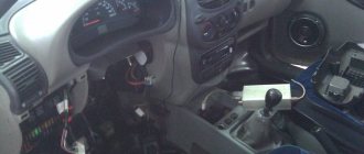
While in the inspection hole, you can begin to unscrew the nut with a socket/socket wrench, previously connected to the lever extension. It is necessary to take into account the high probability that during the operation of the vehicle the nut may become strongly stuck to its seat, as a result of which it will not be possible to unscrew it using the method described above. In this case, you will need to take the following actions:
- Set the gearbox to neutral position.
- Remove the spark plugs and the generator belt.
- Fix the key with the lever so that the end of the extension can be securely rested against the floor of the inspection hole as the crankshaft rotates.
- Apply a short-term pulse by quickly turning the ignition key.
Often the nut begins to give in after 2–3 such manipulations.
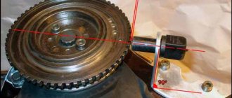
Hold the flywheel from turning and unscrew the pulley mount
Removing the bolt. The crankshaft bolt is found on front wheel drive vehicles. At the same time, its removal is a rather complicated procedure, because you can only get to the bolt by performing the following work in the sequence below:
- Using a jack, raise the front right part of the car body to the required height.
- Remove the front right wheel.
- Place the body on special supports that have a large contact patch with the surface of the bottom of the car.
- Remove the engine guard, generator set belt and air filter.
- To prevent rotation of the crankshaft, use a pry bar or any other suitable object to securely lock the flywheel.
- Unscrew the bolt with a wrench of a suitable size.
VAZ 2110 crankshaft pulley and toothed pulley
When carrying out any repair work in the engine compartment, extreme care should be taken. Rash actions can lead to partial damage or complete failure of some parts of the engine compartment, as well as damage to the paint layer applied to the car body.
Puller
Having removed the fastening element, you can begin to remove the pulley itself. It is most effective to use specialized tools for these purposes, the so-called “pullers”. Using the grips that are present on these devices, the tool is securely attached to the edges of the pulley, after which the part is quite simply removed from its seat.
Crankshaft timing pulley removed
After studying the steps described in the article, even an inexperienced driver should understand how to unscrew the crankshaft pulley without the involvement of third-party specialists.
Replacing the crankshaft position sensor VAZ 2114
One of the most common problems of the VAZ-2114 car is the failure of the DPKV crankshaft position sensor. The fragility and unreliability of the sensor design forces motorists to either shell out considerable sums for repairs at a car service center, or learn the basics of repairs on their own, and, in our economically unstable life, the second option is best. Next, we will teach you how to replace the DPKV with your own hands. So, let's go!
Crankshaft position sensor: principle of operation, types
DPKV is a small electronic device located near the pulley under the hood, which performs a critical function: by transmitting an impulse of the crankshaft position to the engine, the sensor coordinates the movement of the injectors, which directly affects the fuel supply, which, in turn, determines the operation of the ignition system. You need to monitor the condition of the sensor regularly, especially if you have planned a long trip.
Sensors are divided into two types, each of which has its own operating principle:
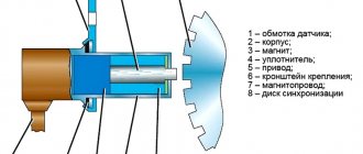
- Inductive. It consists of a magnet and a metal rod wrapped with copper wire. The inductive sensor gives a signal by reacting to the approach of a steel object, that is, the crankshaft.
- Impulsive. The sensor consists of a hall, which changes its position when a metal object approaches it. Due to this, impulses arise, which are then sent to the power unit and determine the operation of the ignition system.
Signs of breakdown
You can determine that the sensor has failed by the following signs:
- Idling malfunctions, instability in engine operation is observed;
- The engine loses power;
- The engine accelerates chaotically or, conversely, slows down;
- Heavy plant;
- During high-speed movement and, especially during acceleration, dips are observed.
The main malfunctions may be the following:
- Mechanical deformation;
- Broken wires or shorted wires (this problem is especially common in used cars);
- Wear of the pulley and other parts.
Repairing the sensor is difficult and almost impossible at home. But replacement is not difficult, and it is not that expensive. Let's now find out how to replace the sensor on a VAZ-2014.
Step-by-step instructions for replacing the sensor
If you strictly follow the instructions, the replacement procedure usually does not take much time.
- First of all, to make further work safe, turn off the ignition and raise the hood.
- We find the device and, if it is covered with dust and dirt, which is observed quite often in the practice of motorists, be sure to use a rag to clean both the sensor and its installation location, so that when installing a new device, there is no short circuit in the wires.
- Now we have access to the device. A positive point is the ease of removing the sensor, which cannot be said about other parts. But here it is very important to observe the subordination of actions: first, by bending the fasteners, remove the block and wires, then, after unscrewing the bolt, carefully, slowly, remove the DPKV
- Just in case, it is worth diagnosing the condition of the pulley; toothed parts are often deformed, which also causes a disruption in the fuel supply system and leads to errors in the data transmitted by the sensor, which can already be dangerous.
- We check that the installation site of the new part is clean.
- We mount the sensor.
Installation is carried out in the reverse order of dismantling: tighten the bolt, fasten the block, start the engine, check the sensor data.
An important point during installation is to maintain the required gap, which should not exceed 1 mm. If the gap is too large, you should select a device of the appropriate size: do not try to fix the DPKV of the wrong type, as this connivance can lead to negative consequences.
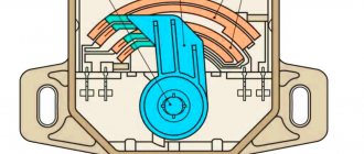
Pulley, or damper, generator drive, its purpose
The multi-belt drive of the generator and other additional units, when installed on the Priora, in addition to transmitting torque from the crankshaft, performs another important job. To understand its meaning, it is worth making a short digression into the ECM.
The principle of operation of an engine with an “injector”
Cars equipped with an ECM are radically different from conventional carburetor cars. The fact is that the ECU (Electronic Control Unit) is responsible for all the actions of the ignition and fuel supply systems. It is he who gives the signals for the formation of a spark in the cylinder chambers. And it sends signals for fuel injection by opening the fuel rail injectors. The question naturally arises, how does the computer know that it is time to issue commands to turn on the necessary nodes?
The crankshaft sensor informs him of this. It is worth considering this process in more detail. This sensor operates on the long and well-known Hall effect. That is, the signal is interrupted when a special technological clearance on the disc being read coincides with the sensor. On “injection” cars, this signal coincides with TDC (Top Dead Center) of the compression stroke of the first cylinder. So, you need to know that on Russian cars it is the pulley that does the work of the information disk.
Which sensor is more reliable?
Many of the world's largest brands produce such equipment. For example, the Siemens concern. Also among popular models are sensors from Perkins, Kazuma and others.
According to the degree of reliability, sensors can be divided into three groups, based on the principle of their operation. The most popular is inductive. This is a simple and reliable option, installed in the vast majority of cars around the world.
In addition to the inductive (magnetic) type, two more types are used:
We recommend: What is a tow bar - purpose, types, electrical, production
Based on the Hall effect. The device is located in a housing equipped with magnetic cores, the teeth of the disk are magnetized. As a result, voltage occurs when a tooth passes near the sensor. An alternating electric current occurs and the signal is sent to the ECU. This design is used less frequently than the inductive one. It is not only more complex in design, it must have a separate power supply. But it guarantees increased accuracy of crankshaft performance measurements. Such sensors are installed on Priora cars.
Optic. Its circuit is based on measuring the crankshaft operation using an LED and a photodiode. A current pulse occurs when either a tooth or a “space” passes between the diodes in place of the tooth. This type is used even less frequently than that based on the Hall effect. Its main disadvantages are vulnerability to operating conditions and the need for constant prevention. Dust, inevitable pollution, etc. often cause the device to transmit the wrong signal, which has a negative effect on the engine.
Varieties of design
Classic pulleys are secured to the shafts with keys. However, this type of fastening is practically unsuitable for frequently changing and alternating loads - the key is cut off or the seating groove is broken, backlash appears, so the generator pulley is put on the shaft without tension, Morse tapers and keys, and is pressed with a nut.
This method ensures no spinning even at maximum speed, taking into account that the shaft diameter is 17 mm, the nut thread is M16, and the steel/steel friction coefficient is 0.15 units.
The nut must be tightened with a force of 40 - 50 Nm in two stages - up to 20 Nm, then tightened to an angle of 70 degrees.
The problems are completely solved by the inertial pulley of the generator - an overrunning clutch of the following design:
- the outer race copies the pulley, has grooves for V-belt or poly-V-belt transmission, the same outer diameter as a regular pulley;
- the inner race is a bushing that fits onto the generator shaft;
- A damper rubber layer, a spring and a roller bearing of a special design are installed between the clips.
This scheme makes it possible to smooth out the crankshaft rotation pulses due to the inconsistent coupling of the races with each other. During sharp acceleration, the outer race smoothly catches up with the inner sleeve. When braking, on the contrary, the inner race equalizes the angular velocity relative to the outer pulley.
Fastening the pulley with a clamping nut
Overrunning clutch design
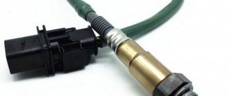
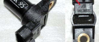
DPKV device
The part is a steel core with a copper wire winding, placed in a plastic case and filled with compound resin.
We recommend: Steering rod - design and malfunctions
There are 3 types of synchronization sensors available:
Optical sensor
- Induction. The operating principle is based on the use of a magnetized core with copper wire wound on it, at the ends of which the change in voltage is measured. In addition to fixing the position of the crankshaft, it measures its rotation speed, which is also necessary for high-quality operation of the internal combustion engine. Induction sensors are the most common and frequently used in automobile devices.
- Optical. Their design is based on an LED, which emits a luminous flux, and a receiver, which captures the light on the other side. When a light beam hits a control tooth, it is interrupted, the receiver records its absence, and the information is transmitted to the computer.
- Hall Sensor. It works based on the physical effect of the same name. A magnet is placed on the crankshaft; when it passes the sensor, a direct current appears in the latter, fixed by a synchronizing disk.
The versatility of an induction-type device and a Hall sensor make them the most popular in the design of modern motors.
Why might difficulties arise?
Removing a pulley is a difficulty in itself, even for a specialist, let alone a beginner. Difficulty may arise when removing the bolt or nut connecting the pulley and crankshaft. The fact is that the direction of the thread when unscrewing it coincides with the direction of the torque during engine operation. Thus, while the engine is running, the bolt is constantly tightened, which results in a serious problem when removing the bolt. Difficulty can also arise if you do not have the right tool.
Folk tricks
Let's look at a few folk car tricks that have helped more than one driver.
- Each threaded connection, by the way, not only on the part of the car, can be unscrewed by first lubricating it with a special oil, for example: HP, sunflower oil, vinegar, brake fluid.
- In rare cases, lightly tapping the edges of the bolt and nut with a hammer or wrench helps.
- Removing a bolt or nut does not mean removing the pulley. How to unscrew the crankshaft pulley without a special key? The pulley sits very firmly on the shaft; it can be removed using a pry bar or a screwdriver and carefully pry it off in several places.
Symptoms of a problem
Signs of a malfunction of the DPKV can be different. Often, dirt adheres to the end of the sensor itself, which can interfere with reading. Also, symptoms of a faulty crankshaft sensor may be as follows:
- The idle mode is unstable;
- Engine speed rises or falls spontaneously;
- Power drops;
- During acceleration, a “failure” is felt;
- The car doesn't start well.
In these cases, for the most part, the VAZ 2114 crankshaft position sensor is replaced.
In addition, the VAZ 2114 crankshaft sensor may well be in good working order. And on the “tidy” the DPKV error will appear (0335 or 0336). The reason for this may be a broken wire near the connector. This is easily determined visually; then it is enough to replace the connector without replacing the sensor itself.
If the owner notices signs of a malfunction of the crankshaft sensor on his car, then this is a “signal” about the need for diagnostics.
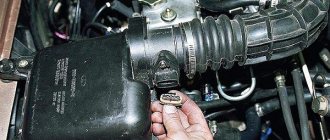
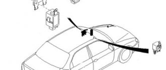
It is not difficult to guess where the crankshaft sensor is located on a VAZ 2114. Like many other VAZ models, it is attached to the engine, and more specifically to the oil pump, near the generator drive pulley, on its cover. The sensor is attached with one bolt, which is typical for many models of this family.
Here is the crankshaft sensor on the VAZ 2114
Typical causes of failure:
- Physical damage to the case;
- The interturn closure of the winding turns entails a change in the generation frequency transmitted to the control unit (frequency type sensors);
- Emergency wear or loss of pulley teeth.
Manufacturers of inertial pulleys
In addition to original spare parts, the most common are INA and Ruville couplings; the quality of parts from these companies is quite acceptable. in the creation of overrunning clutches, she first presented an innovative solution to the world in 1995. In addition to these manufacturers, spare parts are also produced by:
Depending on the manufacturer and model of the car, the cost of an inertial pulley can range from 1,300 to 9,000 rubles. By the way, OMGs are also developed for AvtoVAZ cars - clutches for the VAZ-2110 are produced under the Eldix brand, the price of the spare part in 2017 is approximately 1,700 rubles, and a plug is supplied with the overrunning mechanism.
How to choose where and from whom to overhaul the VAZ 2110 engine?
The first who can provide such services are official service companies, an extensive network of which exists throughout the country. In this case, the use of original spare parts, professional tools and equipment is guaranteed. The personnel of such enterprises undoubtedly have enormous experience and have the necessary knowledge to carry out repairs.
If for some reason you need to choose another campaign, first of all you need to obtain information about the availability of licenses to perform such repairs, as well as whether the workshops are equipped with the necessary equipment and devices. Having experience in the renovation market is also very important when choosing who will do the job.
What can a faulty pulley cause?
First, you need to understand the reasons for the breakdown of this element in order to protect the car owner from unplanned repairs. Breakage can occur even from a small blow; this is due to the fact that during production this part, as well as its inner ring, was not hardened. And this makes them quite fragile. It is entirely possible that it can be destroyed by the presence of even the most insignificant free movement. Therefore, it needs to be well strengthened during installation. During the production process of this element, micro scratches are formed on its surface. These scratches can grow over time, causing the part to malfunction and requiring replacement.
So, what can pulley malfunctions lead to?
- Malfunctions are fraught with consequences not only for the operation of the main unit, but also for the crankshaft. The fact is that while the car is moving, the crankshaft is also in constant motion. Thus, minor vibrations appear, but this is enough for the crankshaft to break. So, it serves as some of his protection and that is why it is so important. It also has a beneficial effect on the operation of the belt, which moves without strong vibrations. The belt also stretches less, which allows it to remain in good condition longer. And if it’s not changed in time, it might even burst.
It is very important to monitor the operation of the pulley, because its malfunction can negatively affect the operation of your machine.
Replacing the alternator pulley in a timely manner can extend the life of both certain small parts and large components of the car.
Sensor types
Sensors differ in operating principle and design features.
- inductive type. Inside there is a metal rod with a magnet at the outer end. It is designed to magnetize the rod. A winding of copper wire is wound around this rod, the ends of which are brought out in the form of connectors for connecting wires. The operating principle of the inductive type crankshaft position sensor: when a steel object is located next to the rod, a signal appears at the terminals.
- The operating principle of the next type of crankshaft sensor is slightly different. It has a hall sensor inside. When a metal object is brought close to it, its state changes (from logical zero to one and vice versa).
- frequency Let's look at how this type of crankshaft sensor works. The engine control unit generates pulses of a certain frequency. They are fed to the sensor and when a metal object is brought to the sensor, the generation frequency changes. By changing the frequency, the controller determines the presence of an object near the sensor. The sensor reacts to the metal of the crankshaft ring teeth (on some cars it is located on the flywheel).
Priora alternator belt size
To choose a Priora alternator belt, you need to check whether the car has air conditioning and what brand it is. You can find the difference between the Halla and Panasonic systems by the following points:
- The extreme right regulator (responsible for air speed) on Panasonic has more than 15 positions, while Hull has only 4.
- When you press the middle Panasonic button, the air conditioning and windshield defogger mode are turned on. On Hull this button does not function (a plug is installed).
There are also differences under the hood: with the Panasonic system the hose is rubber, with the Hull it is aluminum.
The Priora generator belt with air conditioning without power steering for the Halla system and the Panasonic system is marked 6РК1115.
Belt Gates 6pk1113. Photo source: https://xn--80aaagl2dohhc.xn--80aswg/catalog/zapchasti-dlya-otechestvennykh-avtomobilei/remni-generatora/remen-poliklinovoi-2110-12-2170-priora-gates
Without air conditioning, there are two options:
- without power steering, a 742 mm drive is installed;
- The alternator belt on a Lada Priora with power steering without air conditioning is set to 1115 mm.
Belt life
Drive manufacturers claim that the alternator belt for the Lada Priora is 16 cl. without air conditioning it can last 120 thousand km. This is acceptable if all systems work flawlessly and no external factors affect this part of the car. But in reality this is not the case; the operation of the belt is affected by many things, including temperature changes.
Recommendations from experts and Prior owners boil down to the fact that it is better to change the drive every 50-70 thousand km, provided that high-quality spare parts are used.
conclusions
The causes of the malfunction of the crankshaft position sensor of the VAZ-2114 have been established. So, do not forget that you need to make sure whether this is actually the reason, or whether there are other faults with the car. For this, there are diagnostic options that can and should be used.
First, let's look at what a crankshaft position sensor is. The crankshaft position sensor of the VAZ 2114, like many other VAZ models, is an electromagnetic device that transmits information about the position of the crankshaft to the electronic “brains” of engine control. This sensor is very important; the correct operation of the fuel injectors and the ignition system depends on it. It doesn't break down often. But if you are going on a long trip, it is advisable to have a spare one.
Crankshaft position sensor VAZ 2114
Pulley installation
Installation is carried out in the reverse order; you will need the same tool as when unscrewing the pulley/overrunning clutch. The part is put on the shaft and tightened with a nut in two stages:
- with a tightening force of 20 kN;
- then another 70 degrees or with the tightening torque specified in the operating manual for the generator, car model.
Installing a pulley with a thread lock under the nut
After installing the generator belt, the V-belt drive is tensioned in accordance with the requirements of the manual. Typically, when a force of 10 kg is applied with a household steelyard, the belt deflection should be within 1 cm.
( 2 ratings, average 4.5 out of 5 )
Trouble-shooting
It makes sense to repair the sensor in case of such malfunctions as:
- penetration of contamination into the PCV sensor;
- presence of water in the sensor connector;
- breakage of the shielding sheath of the sensor wires or harness;
- changing the polarity of signal wires;
- lack of connection to the wiring harness;
- short circuit to ground of the sensor signal wires;
- reduced or increased mounting gap of the sensor and synchronization disk.
Table: working with minor defects
| Defect | Remedy |
| Penetration of PCV sensor and contaminants |
|
| Presence of water in the sensor connector |
|
| Broken shielding of sensor wires or harness |
|
| Changing the polarity of signal wires |
|
| Sensor not connected to wiring harness |
|
| Short circuit to ground in sensor signal wires |
|
| Reduced or increased mounting gap of the sensor and synchronization disk |
|
We recommend: Learning to change gears on a manual transmission
How to change the crankshaft position sensor?
Important nuances that must be observed when replacing DPKV:
- Before performing dismantling work, it is necessary to apply marks indicating the position of the bolt in relation to the sensor, the DPKV itself, as well as the marking of electrical cables and contacts.
- When dismantling and installing a new PCV sensor, it is recommended to make sure that the synchro disk is operating correctly.
- Replace the measuring device along with the harness and firmware.
To change the PCV sensor you will need:
- new measuring device;
- autotester;
- calipers;
- 10mm wrench.
Algorithm of actions
To change the crankshaft position sensor with your own hands you need to:
- Turn off the ignition.
- De-energize the electronic device by disconnecting the terminal block from the controller.
- Using a wrench, unscrew the screw securing the sensor and remove the faulty DPKV.
- Clean the planting area from oily deposits and dirt with a rag.
- Install the new meter using the old fasteners.
- Carry out control measurements of the gap between the teeth of the generator drive pulley and the sensor core using a caliper. The gap size should correspond to the following values: 1.0 + 0.41 millimeters. If during a control measurement the gap value is less (greater) than the specified value, it is necessary to adjust the position of the sensor.
- Check the resistance of the crankshaft position sensor with an autotester. For a working sensor it should be in the range of 550–750 Ohms.
- Reset the on-board computer to turn off the Check engine signal.
- Connect the crankshaft position sensor to the network (a connector is installed for this).
- Check the functionality of the electrical appliance in different modes: at idle and under dynamic load.
Photo gallery
Unscrewing the bolt with a wrench Taking measurements with a caliper Installing a new DPKV
Renault Megane › Logbook › Replacing generator bearings and installing generator pulley 2110
This means that the rustling noise from under the hood completely bothered me, I even began to suspect the release valve... However, the smell of burnt rubber in traffic jams convinced me to turn my attention to the generator, its bearings and pulley. I took off the belt of the additional equipment and pronounced the verdict - generator bearings. It was lunch time, I removed the generator, brought it to the workshop and began to disassemble it. I’ll say right away, the generator is BOSCH.
Now you can inspect the bearings. The rear (small) one was not changed; no signs of wear were found. But the front one was simply worn out into rubbish. The bearing was purchased from a “tenth” generator, Vologda (VBF) for 110 rubles. Its catalog number is 6303, also known as 180303. The rear bearing is like 6003, unlike the “tenth” one, which is 6202. The difference is in the internal mounting diameter, ours is 17 mm, the external one is 35. The 6202 has an internal 15 mm, the external one is also 35.
At the same time, a 2110 17mm generator pulley was purchased. There are 2 varieties, 17 and 15, here 17 is our size. I also bought a “generator cover repair kit 2110”, but it was not useful.
The main problem was removing the front bearing. On top of it there is a spacer washer, quite rusted. It was impossible to get under it with a puller; it wouldn’t fit together with the bearing, so I had to carefully knock it off. Unfortunately, there are no photographs of this process, because by that moment the phone was put on charge, but I’ll try to describe it in words .
I poured WD40 liquid on it and turned it on the shaft a couple of turns using a chisel. The anchor is GENTLY clamped in a vice through the old belt. Next, I drove a chisel between the washer and the bearing, evenly and from different sides, until the washer began to move towards removal. Then I picked it up with a puller and removed it. The bearing did not yield to the puller and was barbarously sawed off with a cutting machine, without however damaging the shaft. The sawn-off bearing came off easily.