With the advent of injection engines on domestic cars, the number of various sensors has sharply increased. What sensors and control units on Kalina are responsible for what and how to solve problems that arise during operation? Read about this in the current section, which contains detailed manuals with photographs of repair or replacement of ECM parts. Very useful tips are also given that will help extend the life of the entire engine management system.
A couple of days ago I conducted a small experiment with my Kalina. For subsequent sale, an ECU from a VAZ 2114 s was purchased.
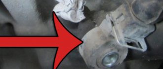
Today I was working in my garage as always, and decided to do a short review on replacing the crankshaft position sensor on all front-wheel drive vehicles.
About a week ago, after checking the compression in the engine of my Kalina, an error appeared from BC State: 0343 - high signal level.
The idle speed control on Kalina is located on the throttle body, namely on the inside next to the throttle position sensor.
I think that not every car owner knows where the speed sensor is located on his Kalina. It’s clear that it’s somewhere on the body.
This Kalina sensor (1.6 - 8 cells) is located on the cylinder head on the left side, right at the end. On the.
Before talking about the procedure for replacing this device, first I would like to write about its purpose and function. Yes.
If you begin to notice that the outside air temperature readings on your car’s on-board computer differ from the real values, then that’s it.
Many Kalina owners are sometimes frightened by scary tales about the electric booster, that it often fails and the steering wheel jams. But relate.
Almost all Lada Kalina owners, especially those who have owned this car for a long time, know about such a problem as flooding.
Before proceeding with this simple and quick replacement, let's first understand what kind of device this is and what it is for.
The mass air flow sensor on a Lada Kalina car may not have to be changed even during the entire period of ownership, since this part is correct.
© Lada Kalina Blog. All rights reserved. Copying of materials is prohibited without the written consent of the copyright owner.
This site is a private unofficial project and does not pursue any commercial purposes. All materials located on this site are provided for informational purposes only, without any warranties, express or implied. The site owner is not responsible for the application of the site information and its use. All risks when using the site are borne by the user. The resource is intended for readers over 18 years of age.
Various sensors are responsible for the operation of all systems of a modern car. They take readings and transmit them to the electronic engine control unit (ECU). If the sensor malfunctions, an error is stored in the memory, and in some cases a Check Engine error appears on the instrument panel.
Where are the sensors located?
All modern Lada cars (Granta, Kalina, Priora, Vesta, Largus, Niva or Lada XRAY) are equipped with domestic VAZ engines. The location of the sensors on these motors is the same:
Elements of the electronic engine control system of the VAZ 11186/11189: 1* – controller; 2* – crankshaft position sensor; 3* – control oxygen concentration sensor; 4* – diagnostic block; 5* – diagnostic oxygen concentration sensor; 6 – throttle control unit; 7* – vehicle speed sensor; 8* – adsorber purge valve; 9* – gas pedal module; 10* – brake signal switch; 11* – clutch pedal position sensor; 12 – battery; 13 – mass air flow sensor; 14 – coolant temperature sensor; 15 – ignition coil; 16 – knock sensor; 17 – spark plugs; 18* – nozzles. *The item is not visible in the photo.
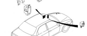
Location of ECM elements in the vehicle interior (for clarity, without dashboard): 1 – clutch pedal position sensor; 2 – brake signal switch; 3 – gas pedal module; 4 – controller.
Coolant temperature sensor (DTOZH)
Designed to measure coolant temperature in the engine cooling system. Based on the indicators, the ECU adjusts the crankshaft speed, the composition of the fuel-air mixture and the ignition timing. The sensor practically does not break, but sometimes it lies. Quite often the wires at the base of the connector fray so much that there is nothing to even solder to. The coolant temperature sensor is installed in the thermostat cover.
Knock sensor (DS)
Designed to determine the moment of occurrence of high-frequency vibrations of the cylinder block that occur during detonation combustion of fuel. Based on the sensor signal, the electronic engine control unit selects the optimal ignition timing, which allows for the most complete and efficient combustion of the fuel-air mixture in the engine cylinders, as well as automatically adjusting the ignition timing for fuels with different octane numbers. The knock sensor is located on the front wall of the cylinder block between the 2nd and 3rd cylinders.
What is a phase sensor used for?
To understand possible malfunctions of the phase sensor, it makes sense to briefly dwell on the question of what it is, as well as the principle of its design.
Thus, the main function of the phase sensor (or DF for short) is to determine the position of the gas distribution mechanism at a specific point in time. In turn, this is necessary so that the electronic engine control unit (ECU) gives the command to inject fuel at a certain point in time.
Phase sensors are used on engines with distributed phased injection. They are also used on engines that use a variable valve timing system. In this case, separate sensors are often used for the camshafts that control the intake and exhaust valves.
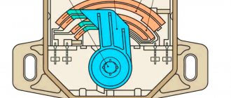
The operation of modern phase sensors is based on the use of a physical phenomenon known as the Hall effect. It lies in the fact that in a semiconductor wafer through which an electric current flows, when it moves in a magnetic field, a potential difference (voltage) arises. A permanent magnet is placed in the sensor body.
In practice, this is implemented in the form of a rectangular plate of semiconductor material, to the four sides of which contacts are connected - two input and two output. Voltage is applied to the first, and a signal is removed from the second. All this happens on the basis of commands coming from the electronic control unit at a specific point in time
There are two types of phase sensors - slot and end. They have different shapes, but work on the same principle. So, on the surface of the camshaft there is a mark (another name is a benchmark), and during its rotation, a magnet included in the sensor design records its passage.
A system (secondary converter) is built into the sensor body, converting the received signal into information “understandable” for the electronic control unit. End sensors are designed in such a way that there is a permanent magnet at their end, which “sees” the passage of a benchmark near the sensor. In slot sensors, the use of the letter “P” shape is implied. And the corresponding reference point on the distribution disk passes between the two planes of the housing of the slotted phase position sensor.
In injection gasoline engines, the master disk and the phase sensor are adjusted in such a way that a pulse from the sensor is generated and transmitted to the ECU at the moment the first cylinder passes its top dead center. This ensures synchronization of fuel supply and the moment of spark supply to ignite the air-fuel mixture. Obviously, the phase sensor has a direct impact on the operation of the engine as a whole.
Mass air flow sensor (MAF)
This important sensor is located behind the engine air filter. It is also called an air flow meter. Its purpose is to estimate the amount of air entering the car engine. Based on the information received from the sensor, the electronic control unit (ECU) calculates the required amount of fuel to maintain the stoichiometric fuel-to-air ratio for the given engine operating conditions.
Malfunctions of the phase sensor on a car with LPG
It is noted that when the engine is running on gasoline or diesel fuel, the unpleasant symptoms described above do not appear so acutely, which is why many motorists often use cars with a faulty phase sensor for a long time. However, if your car is equipped with gas equipment from the fourth generation and higher (which uses its own “smart” electronics), then the engine will work intermittently, and the driving comfort of the car will sharply decrease.
In particular, fuel consumption will increase significantly, the air-fuel mixture may be lean or, conversely, enriched, and engine power and dynamics will significantly decrease. All this happens due to a mismatch between the software of the electronic engine control unit and the LPG control unit.
Accordingly, when using gas-cylinder equipment, the phase sensor must be changed immediately after its breakdown is detected. Using a machine with a damaged camshaft position sensor is harmful in this case not only to the engine, but also directly to the gas equipment and its control system.
Clutch and brake sensors
Based on the signals from the clutch pedal position sensor and the brake light switch, the controller distinguishes between pressed and unpressed pedal positions. When the clutch pedal is pressed, the controller disables engine load regulation. Both sensors are located on the pedal assembly.
Some vehicle versions use an electronic throttle valve drive (E-gas). Let us remind you that in order to understand what errors are recorded in the ECU, you need to decipher them.
Found an error? Select it and press Ctrl+Enter..
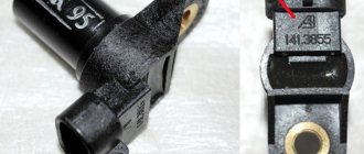
The camshaft sensor Kalina 8 valves becomes unusable from time to time. This can happen for various reasons, but the result is the same - the part needs to be replaced. The situation is similar with the crankshaft position sensor. You will learn in the article how to dismantle old and install new elements of a car of this type.
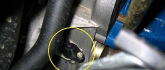
Phase sensor (camshaft position)
You will find this part on the cylinder head on the left side. The operating principle is quite simple. There is a special pin on the camshaft itself. When it passes by the sensor, but sends a signal to it. This moment corresponds to compression of the piston of the first cylinder.
The controller determines the camshaft angle. This is important information for machine systems and sensor failure has certain consequences. The information is sent to the vehicle's ECU, which uses it to control the ignition and fuel supply to each cylinder.
In what situations is replacement required?
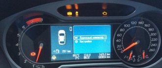
If this part fails, you will see a “Check” indicator on the vehicle’s instrument panel. This is how the ECU signals the driver that the engine needs to be checked. At the same time, the fuel supply pattern changes - it goes to all cylinders simultaneously and, as a result, consumption increases.
The cause of the breakdown may be mechanical damage, as well as other things. There is no point in trying to repair the old unit itself - it costs little and you will waste more nerves and time.
In the video below you will find instructions for replacing this part (the author of the video is Alexandr V).
Replacement instructions
To replace the camshaft sensor, you only need a "10" key . It is better to use a socket with a collar or a ratchet. It will be inconvenient to work with a regular key, although it is still quite possible.
The dismantling and installation procedure is as follows:
- First, disconnect the block with wires by pressing the latch and slightly pulling it up;
- now, using the key, unscrew the part itself;
- it can be pulled out by slightly pulling towards the windshield;
- installation is carried out in the reverse order of steps.
There are no difficulties in this process, but be careful not to damage both the block with wires and the connector for the controller itself on the cylinder block.
Self-replacement
Replacing a faulty oil pressure sensor yourself is quite simple, following the step-by-step instructions:
- To work, you need to prepare a car key for 21.
- First of all, carefully remove the protective cover from the engine.
- Next, you should pay attention to the reverse side of the engine, since the sensor is screwed into the cylinder head “socket” located on the right.
- By pressing the latches, the holding pads must be disconnected from the pad.
- Unscrew the sensor from the “socket” using a key.
- A new sensor is installed in place of the old, failed one. Before installation, carefully wipe the surface of the “nest” with a clean cloth.
- At the last stage, check the reliability of all installed components, fix the protective cover and check whether the problem has been corrected.
If after starting the engine the indicator goes out after a few seconds, this fact will confirm that the light came on precisely because of a malfunction of the oil pressure sensor.
As you can understand, the process of replacing the DDM is quite simple and understandable, so any Lada Kalina car owner can handle such work. If difficulties arise during the replacement process, you should watch the video instructions prepared by professionals at any time.
Crankshaft position sensor
Although this controller rarely fails, its failure can lead to the most unpleasant consequences. You may simply end up in the middle of the road with no way to continue driving.
This element is installed on the oil pump cover. The DPKV transmits information to the ECU so that it can synchronize the fuel supply. Inductive type sensor. As mentioned above, it rarely fails, but this becomes a big problem.
In what situations is replacement required?
If this DPKV is completely out of order, you will not be able to start the engine at all.
But even if it just works intermittently, this can be recognized by a number of signs:
- poor engine starting;
- unstable work;
- power reduction;
- detonation with increasing load.
If you notice such signs and there are no other reasons for them, change the sensor. You can check it by testing the resistance of the windings. If the ohmmeter readings differ from 550-570, then the part is faulty. Fortunately, it costs little and replacement can be done very quickly.
Replacement instructions
To replace this part, you will again need a "10" key and nothing else.
- Turn off the ignition. Then disconnect the wire block by pressing the latch.
- Now, using a wrench, unscrew the fastening bolt.
- All that remains is to remove the old DPKV and install the new one in the reverse order.
Signs of failure
Now let's look at the signs of a faulty crankshaft sensor. In fact, there are not very many of them. These are detonation sounds and detonation under load, when driving uphill at low speeds. You can also feel that the engine is not running as smoothly as before - it lacks stability. At idle, you can notice that they drop quite sharply, and then the number of revolutions grows at tremendous speed. Often the car stalls at idle, both while driving and while standing at a traffic light.
It is often possible to observe a situation where the dynamics of the car have significantly decreased. There are problems starting the engine. One of the most tangible and noticeable signs of a faulty crankshaft sensor is the inability to start the engine at all. This often happens on modern cars. The electronic unit already contains information, thanks to which the engine does not start if the signals from the actuator are unreliable. Another characteristic sign of DPKV failure is the absence of a spark, but not constantly, but periodically.
Video “Checking DPKV”
In the video below you will learn how to check the performance of the DPKV (the author of the video is IZO)))LENTA).
Welcome! Coolant temperature sensors - if we talk specifically about the Lada Kalina car, then there are only two sensor data in it, one goes to the controller (This is the brains, to put it simply), and the other to the device, that is, one sensor shows what the temperature of the coolant in the car is and displays this is all for the device, and another one (which gives readings to the controller) turns on the cooling system fan when the car is boiling, and also regulates the fuel-air mixture (Simply put, when the car is cold, thanks to this sensor it will warm up faster, because the sensor richens the mixture and the temperature immediately rises), both of these sensors are important and if they fail they will cause quite a lot of trouble, especially for the sensor that gives readings to the device, if it stops working, then you simply will not know the temperature of the coolant and in connection with which you can overheat the engine.
How to replace coolant temperature sensors on a VAZ 1117-VAZ 1119?
Removal: 1) These sensors are replaced absolutely identically, but first you need to de-energize the battery, because when working with electronics anything can happen and under no circumstances should there be voltage in the on-board network (Voltage in the on-board network, in other words, in the entire car , can be removed by disconnecting the minus terminal from the battery, for more details on how to do this, read the article: “Replacing the battery on VAZ cars”, everything is written in paragraph 1), after the completed operation we move on, pick up a screwdriver and loosen it with it the screw (Indicated by a red arrow) which connects one end of the air pipe to the air filter housing; as soon as the screw is loosened, disconnect the hose (Indicated by a yellow arrow) in this place and move it aside, thereby giving you good access to both temperature sensors ( One is indicated with a green arrow for clarity, this is the one that goes to the controller), by the way, also remove the screen from the engine if you have one (It is indicated in the photo with a blue arrow), it can be removed quite easily, just take it with your hands on the sides and apply a slight force, remove the screen from the car engine.
Note! Some people completely remove the air filter housing so that it does not interfere, so if you see that it is bothering you and without completely removing it, the sensor you need cannot be replaced, then in this case, remove the air filter housing from the car, read the article on how to do this : “Replacing the air filter housing on a VAZ”!
2) Now drain the coolant from the radiator (For information on how to do this, see the article: “Replacing the coolant on a car”), although you don’t have to drain it, but in this case you need sharp hands and a little dexterity (Which path will you choose It’s up to you, but if you don’t want to drain the liquid from the car, then there’s nothing wrong with it, the main thing is that an air lock does not form, and for this you need to do everything quickly), then disconnect the wire block from the sensor you need (see photo 1 and 2) and taking a wrench or a socket wrench in your hands, unscrew the sensor you also need from the hole in which it is screwed (see photos 3 and 4), when the sensor is unscrewed, remove it from the car, in that case if you did not want to drain the liquid from the radiator, then it will immediately flow out as soon as you remove the sensor, so here you need to remove the sensor a little differently (the same dexterity is needed that we talked about earlier), this is all done as follows, in the beginning you use a wrench Use the key to turn the sensor out a little, and when it’s about to turn out, take the new sensor in one hand and remove the key, while you begin to turn the old sensor out a little with your fingers, pressing it at the same time (otherwise liquid will flow through the holes if you don’t press), how As soon as you understand that the sensor is unscrewed and the liquid does not pour out, it is only because you press it, sharply remove it and put a new one in its place, while also pressing, screw in the new sensor little by little and check whether it works or not.
Note! Photos 1 and 3 above show the sensor going to the controller, while photos 2 and 4 show the sensor going to the device, so be careful!
Installation: The new sensor is installed in its place in the reverse order of removal; when installing, you can lubricate it with sealant so that liquid does not leak through it; in addition, you can check the functionality of the old sensor, for this, prepare a multi-meter and a kettle with a thermometer and a mug, then put the kettle on and wait until it boils or just warms up a little, then pour water into a mug and throw the sensor in there, but just make sure you don’t drown it with the contacts, otherwise it will immediately stop working (the sensor needs to be thrown in exactly the same way as shown in the photo below , in this photo you can clearly see that the contacts of the sensor are not in the water but on the top and thus nothing will happen to the sensor), as soon as the work is done, pick up a multi-meter and connect the leads coming from it to the sensor (Black wire throw it to minus, that is, more simply put, on the metal part of the sensor body, and connect the other, red wire, to the sensor contact), after which the multi-meter should give readings (see. table under the photo below, checking the thermometer and the readings of the device, the readings should be exactly the same or very slightly different as indicated in the table) in connection with which you will determine whether your sensor is working or not.
How to check the phase sensor
Checking the functionality of the internal combustion engine phase sensor is carried out using a diagnostic tool, as well as using an electronic multimeter capable of operating in DC voltage measurement mode. We will discuss an example of a test for phase sensors of a VAZ-2114 car. On models with a 16-valve engine, a sensor model 21120-3706040 is installed, and on 8-valve engines - 21110-3706040.
First of all, before diagnostics, the sensors must be removed from their mounting location. After this, you need to visually inspect the DF housing, as well as its contacts and terminal block. If there is dirt and/or debris on the contacts, it must be removed with alcohol or gasoline.
To check the sensor of the 8-valve engine 21110-3706040, it must be connected to a battery and an electronic multimeter according to the diagram shown in the figure.
Next, the verification algorithm will be as follows:
- Set the supply voltage to 13.5±0.5 Volts (you can use a regular car battery for power supply).
- In this case, the voltage between the signal wire and ground must be at least 90% of the supply (that is, 0.9V). If it is lower, and even more so equal or close to zero, then the sensor is faulty.
- Bring a steel plate to the end of the sensor (with which it is directed towards the camshaft reference).
- If the sensor is working properly, then the voltage between the signal wire and ground should be no more than 0.4 Volts. If more, it means the sensor is faulty.
- Remove the steel plate from the end of the sensor, the voltage on the signal wire should again return to the original 90% of the supply voltage.
To check the phase sensor of a 16-valve engine 21120-3706040, it must be connected to a power supply and a multimeter according to the diagram shown in the second figure.
To test the corresponding phase sensor, you will need a metal piece with a width of at least 20 mm, a length of at least 80 mm and a thickness of 0.5 mm. The verification algorithm will be similar, however, with other voltage values:
- Set the supply voltage on the sensor to 13.5±0.5 Volts.
- In this case, if the sensor is working properly, then the voltage between the signal wire and ground should not exceed 0.4 Volts.
- Place a pre-prepared steel piece into the sensor slot where the camshaft reference is placed.
- If the sensor is working properly, then the voltage on the signal wire should be at least 90% of the supply voltage.
- Remove the plate from the sensor, and the voltage should again drop to a value of no more than 0.4 Volts.
In principle, such checks can be performed without removing the sensor from its mounting location. However, to inspect it, it is better to remove it. Often, when checking a sensor, it makes sense to check the integrity of the wires, as well as the quality of the contacts. For example, there are cases when the chip does not hold the contact tightly, which is why the sensor does not receive a signal to the electronic control unit. Also, if possible, it is advisable to “ring” the wires going from the sensor to the ECU and to the relay (power wire).
New Lada: MAF Kalina: what is it for, causes of malfunction,
In addition to checking with a multimeter, you need to check for relevant sensor errors using a diagnostic tool. If such errors are detected for the first time, you can try to reset them using software, or simply by disconnecting the negative terminal of the battery for a few seconds. If the error appears again, additional diagnostics are needed using the above algorithms.
Typical phase sensor errors:
- P0340 - no camshaft position sensor signal;
- P0341 - valve timing does not coincide with the compression/intake strokes of the cylinder-piston group;
- P0342 - the signal level in the electrical circuit of the DPRV is too low (detected when there is a short to ground);
- P0343 - the signal level from the meter exceeds the norm (usually occurs when the wiring is broken);
- P0339 - an intermittent signal is received from the sensor.
Thus, if these errors are detected, it is advisable to perform additional diagnostics as quickly as possible so that the engine operates in optimal operating mode.
All engine sensors 21116, 21126, 21127
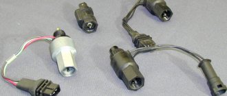
Each sensor is equipped with a connector fixed to its body:
The second contact of the sensor is the housing itself
The smooth operation of the engine is ensured by a set of elements:
- The air flow sensor (AFS) is part of the intake system. Not used on engines 21127. The part is designated as 11180-1130010;
- Two throttle position sensors - variable resistors, built into the throttle pipe;
- The antifreeze temperature sensor is a thermistor with a screw fastening, screwed into the thermostat housing. Catalog number – 21120-3851010;
- The knock sensor is a piezoelectric element with two leads, mounted on the cylinder block body. Catalog number – 21120-3855020;
- Two oxygen sensors (OS), diagnostic and control, are equipped with a screw mount and are screwed into the exhaust pipe housing. 21074-3850010 is the designation of each module;
- The speed sensor is an electronic module, mounted on the top of the gearbox housing. Catalog designation – 21700-3843010;
- The crankshaft position sensor (CPS) is an electronic module mounted on the oil pump housing. Designated as 21120-3847010;
- The phase sensor is an electronic module designated 21120-3706040. 21116 is not used in the engine design;
- Oil pressure sensor - has a screw mount, designated as 11180-3829010.
The element indicated under number “9” will be installed at different points depending on the configuration (see photo). The third figure shows where sensor “8” is attached:
The design of the resonant intake system uses a separate sensor that measures air temperature and pressure. The element is designated as 21800-1413010:
Engine air pressure and temperature sensor 21127
The design of the throttle valve modules was not considered. The bug has been corrected below.
For different Kalina-2 engines, their own module, unique in design, is suitable, containing an electrically driven throttle valve:
- 21126-1148010 – the element is intended for internal combustion engine 21126;
- 21127-1148010 – part of the engine 21127 design;
- 21116-1148010 – part of the intake tract of the 8-valve engine (21116).
The module body is made of light alloys and is equipped with a connector to which the contacts of the sensors and the electric motor are connected.
Engine throttle assembly 21126
If necessary, it is better to replace the module as an assembly rather than try to repair it.
When manipulating electrical equipment, you need to disconnect the negative terminal from the battery. The requirement also applies to the operation of replacing sensors.
Self-replacement of the sensor on the Lada Kalina
To replace the oil pressure sensor on a Lada Kalina, use the instructions below.
- Open the hood.
- Remove the decorative motor cover.
- Press the terminal block lock and remove it.
- Unscrew the sensor. It is convenient to tear it out of place with a key. Subsequently, the DDM can be unscrewed by hand.
- Install the new sensor, initially by tightening it by hand and then tightening it with a wrench.
- Connect the terminal block to the oil pressure sensor.
- Replace the decorative cover.
- Start the power plant, monitoring the ignition and extinguishing of the indicator.
Troubleshooting
The sensor that determines the angle of rotation is a variable resistor with 3 terminals. The thermistor, as well as the piezoelectric element, are equipped with two contacts. The crankshaft position sensor consists of a solenoid and a magnet. But speed and phase sensors contain electronics in their design.
Note that failure of the phase sensor does not lead to breakdown or shutdown of the engine. The same can be said about the speed meter.
Each of the two oxygen sensors is a complex electronic device. But the reliability of their circuits can be considered high. Hall effect sensors, used for speed and phase control, fail more often than the oxygen analyzer.
Oxygen sensor for engines 21116, 26, 27
A variable resistor used in any design is duplicated. If the indicators obtained from two “horseshoes” differ, then the Check lamp turns on.
All errors, including breaks and short circuits of sensor contacts, are constantly monitored by the ECU.
Let's say the Check Engine light doesn't come on. If you feel that the power has decreased and the dynamics have deteriorated, try replacing one of the elements: