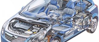
VAZ-2110 engines with a two-shaft head with 16 valves are built on the basis of the old one and a half liter VAZ 21083 engine. Changes affected only the cylinder head and air supply system. Twin-shaft 16-valve engines were installed in two types - a 1.5-liter engine (VAZ-2112) and a 1.6-liter engine (VAZ-21124). The ignition system on these engines is different. Today we will look at the ignition module for the injection 16-valve engine 2112 and find out its differences from the 1.6-liter engine 21124.
Technical specifications
The VAZ 2110 engine has high performance. At the same time, several variants of power units from AvtoVAZ were installed on the vehicle during the production process. The “Ten” had in its arsenal several variants of a sixteen-valve engine.
Let's look at the main technical characteristics of the VAZ engines with which the 16-valve model 2110 was equipped:
VAZ 21120
| Name | Index |
| Volume | 1.5 liter (1499 cm3) |
| Number of cylinders | 4 |
| Number of valves | 16 |
| Fuel | Petrol |
| Injection system | Injector |
| Power | 93 hp |
| Fuel consumption | 7.0 l/100 km |
| Cylinder diameter | 82 mm |
Not a very popular version of the power unit. Although the engine power is high, as practice has shown, this engine did not take root on the VAZ 2110, since it had a number of design flaws. Basically, the engine was installed on a car marked VAZ 21103.
VAZ 21124
| Name | Index |
| Volume | 1.6 liter (1599 cc) |
| Number of cylinders | 4 |
| Number of valves | 16 |
| Fuel | Petrol |
| Injection system | Injector |
| Power | 89.1 hp |
| Fuel consumption | 7.0 l/100 km |
| Cylinder diameter | 82 mm |
A sixteen-valve version of the power unit, which received almost 100 horsepower and had high technical characteristics.
The average lifespan of a Lada engine is 250,000 km. If you use high-quality oil in the VAZ 2110 engine, you can increase the service life of the power unit by 20-30 thousand km.
Symptoms of module malfunction
Signs of a faulty ignition module on a VAZ-2110 are always acutely felt:
- hesitant engine starting or failure to start;
- failures during sudden changes in speed;
- high fuel consumption;
- two cylinders do not work, the engine is feverish;
- lack of dynamics;
- a sharp drop in power;
- drop in power and thrust after warming up.
Other faults
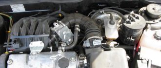
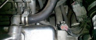
We unscrew and look at the spark plugs.
Checking the high voltage wires.
These symptoms may not only be caused by the ignition module. To determine the malfunction, it is enough to spend a few minutes diagnosing spark plugs, high-voltage wires and caps. This will eliminate the remaining elements of the ignition system and make sure that it is the ignition module that is faulty.
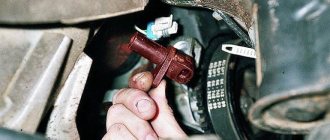
- Checking the spark plugs . To do this, unscrew them, put on the caps, place them on the cylinder head and crank the engine with the starter. The spark should be stable on all spark plugs. We replace non-working spark plugs and repeat the test. Under no circumstances should you crank the engine with the starter with the high-voltage wires removed. This will lead to a breakdown in the ignition module cover.
- Checking the high voltage wires . We remove the caps and hold the wire contact through the insulator at a distance of 10-15 mm from the head . With good wires, the spark should pierce this distance vigorously and confidently. Next we check the wires for resistance. A working wire should have a nominal resistance of 7-10 kOhm. Any deviation from this value indicates the need to replace the entire set of high-voltage wires.
- Checking the caps for breakdown.
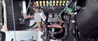
We also look at the block and especially the wires included in it.
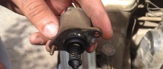
If all these elements are in good condition, the ignition module must be checked.
In addition, it is better to check the spark plugs and wires on a warm engine, since a half-dead ignition module can operate cold for some time and fail when heated. You also need to be sure that all sensors are working properly. This can be indicated by an error code or Check Engine light.
Algorithm for checking the ignition module on a VAZ-2110
We begin the test with the block connected to the module.
To check the module, we only need a multimeter and it will take 15-20 . This is quite simple to do, the main thing is to adhere to the algorithm and know the nominal values of the working module:
- We check the power supply and the presence of pulses supplied from the ECU . We check the power between the central terminal (15) of the wire block connected to the module and the engine ground. When the ignition is on, the voltage should not be less than 12 V. Otherwise, either the battery is dead or the ECU does not work.
- We check the pulses from the ECU on the wiring block . We install one tester probe on connector 15, the second on the far right, then on the far left. The assistant cranks the engine with the starter, and at this time we record short-term voltage surges with a tester. If there are no impulses from the ECU, it is he who is to blame.
- We check the resistance on the secondary windings of the coils . We put the tester in resistance measurement mode and measure it at the high-voltage terminals of the module cover. Between pins 1 and 4 and pins 2-3, the resistance should be 5.4 kOhm. Otherwise, the module must be replaced.
- We check the resistance of the primary windings between contacts 15 and the rightmost, then the leftmost terminals. Nominal - 0.5 Ohm . Deviation is not allowed.
- Check the module for a short circuit . In ohmmeter mode, install one multimeter probe on the central terminal, the second on the metal body. There shouldn't be any resistance. If the device detects at least some resistance (other than unity or infinity), the module must be replaced.
Service
VAZ 2110 engines are serviced quite typically. Thus, scheduled maintenance is carried out within 10-15 thousand km. If the vehicle is operated on LPG, then maintenance must be reduced to 8-10 thousand km in order to preserve the engine and extend its service life.
When servicing, it is necessary to pour only high-quality oils into the VAZ 2110 engine. Thus, there are a number of lubricating fluids that must be poured into the engine. Do not forget about using a high-quality oil filter, which will also affect the service life. The power unit maintenance scheme is quite simple, and is provided by AvtoVAZ in the repair manuals.
The VAZ 2110 engine with 16 valves is quite unpretentious in the use of oil. So, both semi-synthetic and synthetic lubricant are ideal for him. Many car enthusiasts ask the question: how much oil should be poured into the engine? Almost all engines require 3.5 liters of oil.
Overhaul of VAZ 2111 engine
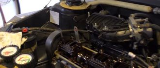
Overhauling an engine is a rather labor-intensive process; in this article we will consider the entire process of such repairs using the example of a 1.5 liter VAZ-21113 16V engine from 2000, after traveling 95 thousand km. During the repair, the following parts were removed and replaced:
First of all, we get rid of antifreeze and oil.
When unscrewing the cover, remove the receiver mount.
We get rid of the throttle cable and connectors from the diesel engine, remove the ground wires.
It's worth removing the receiver.
In front of you is a receiver, explosive wires and spark plugs.
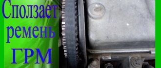
Armed with a 10mm wrench, unscrew the bolts that secure the timing belt cover.
We remove the ground wires, and then the gas pipe mounting bracket.
We place the front wheel on the jack, after aligning the marks, remove the bolts securing the gears, as well as the roller nuts.
After this, we remove the gears, the main thing is to protect them from losing the key, and remove the rollers and cover. First, you may have to remove the pulley located on the crankshaft.
Before removing the fastening bolts, you should hit the threads a little with a hammer, this should be done through a wrench.
Then unscrew the fastening bolts holding the ramp and hexagon.
After removing the bolt, remove the dipstick along with the trunk.
We take out the ramp, as well as the injectors, move it to the right, and pull it towards us.
We put it aside; do not unscrew the hoses.
Remove the head cover.
Perhaps the bracket will get in the way, you should remove it.
To remove the middle head, unscrew the fastening bolts; there are cases of removing the camshaft along with the head, like mine.
We remove the camshafts and spark plug wells.
Malfunctions
A major overhaul of a VAZ 2110 engine means restoring the engine and its components to factory standards. This operation is carried out when the motor has passed its service life and there is exhaustion in the main components.
Due to the fact that the engines have been in use for a long time, some engines are 10-15 years old, a major overhaul is inevitable. So, the combustion chambers have already worn out, and the pistons have burned out from service life and mileage. In addition, engine oil for the VAZ 2110 no longer helps to maintain performance to such an extent.
So, it is worth repairing the power unit at a car service center, especially with regard to the 16-valve engine. The VAZ 2110 8-valve engine is used by most motorists in garage conditions, since it has a simple design that is similar to the Classic and Samara power units.
Detailed instructions for disassembling and repairing the VAZ 2110 engine:
2. Remove the clutch from the engine.
3. Remove the tension roller, camshaft drive belt and spacer washer, which is installed under the tension roller.
4. Remove the toothed pulley from the camshaft.
5. We unscrew four bolts, three of which attach the water pump. Unscrew the fastening nut on the rear cover of the camshaft drive belt and remove the cover.
6. To remove the water pump, insert a screwdriver between the block and the flange of the pump housing and thus move it from its seat. After completing these operations, remove the water pump.
7. Remove the head from the cylinder block.
8. Unscrew the bolts (there are 16 of them) securing the oil sump, then remove it together with the gasket.
9. Unscrew the bolts (there are 3 of them) securing the oil receiver and remove it. Please note that there are spring washers under the bolt heads.
ECU diagnostics
In modern times, many methods have become available for conducting self-diagnosis or diagnosing a power plant malfunction with your own hands. Without any problems, you can purchase various diagnostic equipment, and you don’t have to go to a car service center. So, you can connect to the ECU using a standard OBD II cable and a tablet, or purchase an ELM 327.
Also, some errors can be diagnosed using the instrument cluster. First you need to enable test mode:
- The ignition is turned off. Battery included.
- Press the “Reset” control button and, holding it pressed, turn on the ignition. All positions of the familiar areas (segments) should light up on the LCD – LCD control.
- Press any of the control buttons. The LCD should display the program version (Ver 1.0).
- Press any of the control buttons. The following error codes (if any) should be displayed on the positions of the first and second lines of the LCD.
- Press the “Reset” control button and hold it for no more than 3 seconds. (maybe a typo, I need more than 3c). Error codes should clear to zero.
- Press any of the control buttons. All positions of symbols (segments) should light up on the LCD – LCD control.
Error codes: 2-overvoltage of on-board network;
3-fuel level sensor error (if a break in the sensor circuit is detected within 20s);
4-error of the coolant temperature sensor (if an open circuit of the sensor is detected within 20s);
5-outside temperature sensor error (if there are no sensor readings within 20s, indication on the LCD is “-C”);
6-engine overheating (the criterion for triggering the acoustic alarm is met);
7-emergency oil pressure (the criterion for triggering the acoustic alarm is met);
8-defect of the brake system (the criterion for triggering the acoustic alarm is met);
The 9-battery is discharged (the criterion for triggering the acoustic alarm has been met);
E-determination of an error in a data packet stored in EEPROM.
Diagram of VAZ 2110 injector 16 valves
1 - headlight 35 - instrument lighting switch 2 - front brake pad wear sensors 36 - ignition switch 3 - reverse light switch 37 - mounting block 4 - engine cooling fan electric motor 38 - recirculation valve switch 5 - sound signal 39 - controller heater 6 - right front door locking motor 40 - hazard warning switch 7 - power window relay 41 - heater control lever illumination lamp 8 - 8 A fuse 42 - glove compartment lighting lamp 9 - starter 43 - glove compartment lighting lamp switch 10 - battery 44 - cigarette lighter 11 - generator 45 - on-board control system display unit 12 - windshield washer motor 46 - ashtray lighting lamp 13 - washer fluid level sensor 47 - brake signal switch 14 - left front door locking motor 48 - locking motor left rear door 15 — power window switch of the left front door 49 — power window switch of the left rear door 16 — coolant level sensor 50 — power window motor of the left rear door 17 — windshield wiper motor 51 — socket for a portable lamp 18 — recirculation valve 52 — clock 19 - micromotor gearbox for heater flap drive 53 - gearmotor for electric window lift on the right rear door 20 - electric motor for heater 54 - power window switch at the right rear door 21 - trunk lock switch 55 - gearmotor for locking the right rear door 22 - power window switch at the right front door 56 - side turn signal 23 - electric window motor of the right front door 57 - parking brake warning lamp switch 24 - door lock system control unit 58 - driver's seat belt sensor 25 - additional heater motor resistor 59 - directional light bulb 26 - brake fluid level sensor 60 - interior light bulb 27 - electric window motor of the left front door 61 — interior air temperature sensor 28 — exterior lighting switch 62 — switch in the front door pillar 29 — instrument cluster 63 — switch in the rear door pillar 30 — rear fog light switch 64 — external rear light 31 — warning lamp fog light 65 - interior rear light 32 - rear window heating indicator light 66 - license plate lights 33 - rear window heating switch 67 - trunk light 34 - steering column switch A - blocks for connecting the rear window washer motor B - blocks for connecting the harness injection system C - to the warning light harness block D - block for connection to the on-board computer E - to the headlight cleaner harness block F - block for connection to the fuel level sensor in the electric fuel pump module G - to the rear window heating element H - block for connecting an additional signal braking J - to the trunk lock motor
Useful: VAZ ignition switch pinout
See the complete diagram in one file below (click to enlarge):
Error codes
Error codes from the engine's electronic control unit can often identify faults in electrical circuits and basic systems. Diagnostics are usually carried out to identify faulty sensors.
Decoding the error code: 0102 Low signal level of the mass air flow sensor 0103 High level of the mass air flow sensor 0112 Low level of the intake air temperature sensor 0113 High level of the intake air temperature sensor 0115 Incorrect signal of the coolant temperature sensor 0116 Incorrect signal of the coolant temperature sensor 0117 Low coolant temperature sensor signal level 0118 Coolant temperature sensor signal high 0122 Throttle position sensor signal low 0123 Throttle position sensor signal high 0130 Oxygen sensor 1 signal incorrect 0131 Oxygen sensor 1 signal low 0132 Crankshaft sensor signal high 1 0133 Oxygen sensor 1 response slow 0134 Oxygen sensor 1 signal missing 0135 Oxygen sensor 1 heater fault 0136 Oxygen sensor 2 short to ground 0137 Oxygen sensor 2 signal low 0138 Oxygen sensor 2 signal high 0140 Oxygen sensor 2 open 0141 Oxygen sensor heater fault 2 0171 Mixture too lean 0172 Mixture too rich 0201 Injector control circuit open 1 0202 Injector control circuit open 2 0203 Injector control circuit open 3 0204 Injector control circuit 4 open 0261 Injector circuit short to ground 1 0264 Injector circuit short to ground 2 026 7 Short circuit to ground of injector circuit 3 0270 Short to ground of injector 4 circuit 0262 Short to +12V of injector 1 circuit 0265 Short to +12V of injector 2 circuit 0268 Short to +12V of injector 3 circuit 0271 Short to +12V of injector 4 circuit 0300 Many misfires 03 01 Misfire in cylinder 1 0302 Misfire in cylinder 2 0303 Misfire in cylinder 3 0304 Misfire in cylinder 4 0325 Open circuit of knock sensor 0327 Low signal level of knock sensor 0328 High level of knock sensor signal 0335 Incorrect signal from crankshaft position sensor 0336 Error in position sensor signal crankshaft 0340 Phase sensor error 0342 Low phase sensor signal 0343 High phase sensor signal 0422 Low converter efficiency 0443 Malfunction of the canister purge valve circuit 0444 Short or open circuit of the canister purge valve 0445 Short to ground of the canister purge valve 0480 Malfunction of the fan circuit a cooling 1 0500 Incorrect sensor signal speed 0501 Incorrect speed sensor signal 0503 Interruption of speed sensor signal 0505 Idle speed controller error 0506 Low idle speed 0507 High idle speed 0560 Incorrect on-board network voltage 0562 Low on-board network voltage 0563 High on-board network voltage 0601 ROM error 0603 Error External RAM 0604 Error Internal RAM 0607 Knock channel malfunction 1102 Oxygen sensor heater resistance low 1115 Oxygen sensor heater circuit faulty 1123 Idle rich 1124 Idle lean 1127 Part Load rich 1128 Part Load lean 1135 Sensor heater circuit oxygen 1 break, short circuit 1136 A rich mixture in small load 1137 Poor mixture in small load mode 1140 The measured load differs from calculating +12V 1425 Control circuit of the canister purge valve short circuit to ground 1426 Control circuit of the canister purge valve open 1500 Open circuit of the fuel pump relay control circuit 1501 Short circuit to ground of the fuel pump relay control circuit 1502 Short circuit to +12V of the fuel pump relay control circuit 1509 Overload of the idle speed regulator control circuit a 1513 Idle air control circuit short circuit to ground 1514 Idle air control circuit short circuit to +12V, open 1541 Fuel pump relay control circuit open 1570 Incorrect APS signal 1600 No connection with APS 1602 Loss of on-board power supply voltage to the ECU 1603 EEPROM error 1606 Yes rough road mark incorrect signal 1616 Rough road sensor low signal 1612 ECU reset error 1617 Rough road sensor high signal 1620 RFOM error 1621 RAM error 1622 EPROM error 1640 EEPROM Test error 1689 Incorrect error codes 0337 Crankshaft position sensor, short to ground 0338 Crankshaft position sensor, open circuit 0441 Air flow through the valve is incorrect 0481 Cooling fan circuit malfunction 2 0615 Starter relay circuit open 0616 Starter relay circuit short circuit to ground 0617 Starter relay circuit short circuit to +12V 1141 Oxygen sensor 1 heater malfunction after the neutralizer 230 Fuel pump relay circuit malfunction 26 3 Driver failure Injector 1 266 Injector Driver 2 Malfunction 269 Injector Driver 3 Malfunction 272 Injector Driver 4 Malfunction 650 CheckEngine Lamp Circuit Malfunction
Factors that can cause injector (nozzle) malfunction
VAZ 2110 how to flush the injector
VAZ 2110 how to clean the injector
A malfunction of the injector leads to fuel spraying onto the cylinders with a narrow probe, and this in turn directly affects the efficiency of the engine cylinders. As a result, gasoline mixes little with air, and this in turn leads to:
Note. It is recommended to wash the injector every 30 thousand kilometers.
Basic principles and nuances of injector flushing
VAZ 2110, wash the injector yourself
When to flush the injector of a VAZ 2110
Components that are necessary to flush the injector:
Note. All of the above components can and should be purchased at a company auto parts store. The store’s consultants will help you understand the nuances and assemble a complete, high-quality washing kit.
Professional injector cleaning kit
Injector flushing algorithm:
Note. You can use a car battery as a power source.
Note. It is advisable to seal the place where the tube is connected to the cylinder; for this purpose, you can use electrical tape.
Note. The nozzle should be cleaned until a wide droplet stream of transparent color appears.
Example of washing injector nozzles
The use of photo and video materials will allow you to create a 3D projection of the entire process in your mind. The instructions are simple; they will allow you to clean the injector yourself and in a short period of time. The price of the entire self-cleaning process is low, the main thing is to adhere to the above provisions.
Source