The intake manifold, or as it is popularly called the receiver, is a device that ensures a uniform flow of purified air into the cylinder head. The Priora receiver is subject to tuning and modifications, which we will talk about in this article.
In addition, the receiver accumulates air and smoothes out its vibrations, thereby ensuring smooth engine operation due to a uniform (without drops) supply of air masses. When the unit operates correctly, a highly saturated air-fuel mixture is supplied, and lower fuel consumption is achieved when the engine is running.
Reasons for replacing the Lada Priora receiver
There are a considerable number of varieties of intake manifolds, for example, made from various types of metals or composite materials. However, the Priora receiver is made entirely of plastic. This material prevents excessive heating of the manifold due to a hot car engine.
Thus, the air flow characteristics are improved, which has a positive effect on the proportions and quality of the air-fuel mixture. However, plastic also has a main, negative side - fragility. As a result, numerous breakdowns occur both due to the fault of the car owner and due to low temperatures at which the plastic loses its strength coefficient.
The most common damage can be caused by: - road traffic accidents (even minor ones); — accidental impacts during any repair work in the engine compartment; — other reasons;
If the receiver on your car has through holes or any other leaks, then it must be repaired (if possible) or replaced. If a part is faulty, air loss will occur, resulting in improper engine operation.
How to remove the receiver on a Priora
Tools that may come in handy: - 10mm socket; - key 13; - screwdriver.
To remove the intake manifold you will need:
- Due to the fact that in the next steps of the instructions there will be manipulations with electrical wiring, it is necessary to remove the negative terminal of the battery.
- The next step is to remove the plastic screen (cover) from the engine housing. This is done so that it does not interfere with your work.
- After which, it is necessary to remove power from the four ignition coils and dismantle them. To do this, pull out the contact chips. Take a 10mm socket (or a wrench of the same size) and unscrew one fastening bolt on each coil. Simply pull the coils upwards using the necessary force. Now they can be removed. There is no need to remove the spark plugs themselves; they will not interfere with removal. On the other hand, it is advisable to take advantage of the situation and check their condition (gap and spark quality).
Installing a receiver on a Priora
As usual, installation is carried out in the same way as removal, however, during its production you must be extremely careful not to damage the receiver body. It is extremely important to insert the installed part with the holes into the connecting pins of the cylinder block, after which the manifold is directed to the mounting points on the engine.
Small but important points for installation:
- always clean or lubricate the rubber seals installed at the points of contact between the receiver and the cylinder block;
- Properly tighten the nuts at the joints of the elements.
Which receiver is better for Priora?
There is no clear answer to this question. Each situation is individual. However, some comparisons can be made between receivers made of plastic and aluminum.
Advantages of aluminum products:
- higher strength and wear resistance;
- increased engine power due to design features and a larger volume of supplied air;
- Some models are easier to install and therefore easier to remove.
In addition, the shape of the collector itself plays an important role in ensuring increased power, which should not contain sharp corners and transitions. The most important difference between plastic and metal is the strength and durability of the latter. Therefore, we can recommend installing metal types of intake manifolds for Lada Priora cars.
Operations performed when replacing the cathode collector on a VAZ 2170 2171 2172 Lada Priora
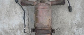
The nuts securing the catalytic converter to the cylinder head are difficult to access. In addition, the collector flange is sealed with a metal-reinforced gasket. The sealing gasket must be replaced every time the connection is disassembled. Before removing the catalytic converter, it is necessary to remove the intake manifold - this will facilitate access to its mounting.
1. Remove the decorative engine casing (see “Removing and installing the decorative engine casing on a VAZ 2170 2171 2172 Lada Priora” ).2. Remove the wire from the negative terminal of the battery.3. Disconnect the exhaust pipe of the additional muffler from the exhaust manifold by unscrewing the nuts securing the intake pipe flange to the exhaust manifold flange and remove the exhaust pipe flange from the studs of the exhaust manifold flange (see “Replacing the additional muffler on a VAZ 2170 2171 2172 Lada Priora”). 4. Remove the air filter (see “Removing and installing the air filter on a VAZ 2170 2171 2172 Lada Priora”).
5. Remove the air supply hose and three hoses of the crankcase ventilation system (see “Cleaning the crankcase ventilation system on a VAZ 2170 2171 2172 Lada Priora”).
6. Disconnect the four connectors of the ignition module wiring harness and move the harness to the side. Remove the ignition modules (see “Removing and installing ignition coils on a VAZ 2170 2171 2172 Lada Priora”).
Engine repair, checking and troubleshooting the engine of the Lada 2170, the procedure for assembling and disassembling the power unit of the Lada 2171, stages of replacing the timing belt of the Lada Priora. Maintenance of the power supply system, cooling, lubrication, exhaust gases of the VAZ 2170 Priora engine, engine repair manual, cylinder heads of the VAZ 2172 Priora. Modifications of the VAZ 2171 Priora engine.
Between the flanges of the Lada Priora cylinder head and the catalytic collector there is a sealing gasket made of two thin molded metal strips connected by spot welding. If the gasket is leaking, exhaust gases break out, accompanied by a characteristic sharp sound. If the malfunction cannot be eliminated by tightening the catalytic converter fastening, replace the gasket. You will need: keys “10”, “13”, socket head “13”, pliers, ruler, feeler gauge. 1. Disconnect the wire from the negative terminal of the battery. 2. Remove the decorative engine cover of the VAZ 2170 (see “Removing and installing the decorative engine cover of the Lada Priora”). 3. Disconnect the exhaust pipe of the additional muffler from the exhaust manifold, for which unscrew the nuts securing the exhaust pipe flange to the exhaust manifold flange, disconnect the suspension cushions from the muffler brackets and remove the exhaust pipe flange from the studs of the exhaust pipe flange of the Lada Priora. Remove the additional muffler (see “Replacing the additional muffler”). 4. Press the latches...
5. ...and disconnect the wiring harness blocks of the control and diagnostic oxygen concentration sensors from the engine harness. 6. Press out the antennae of the holders... 7. ...and disconnect the holders of the wiring harnesses of the control and diagnostic oxygen concentration sensors from the heat-insulating shield of the Lada Priora steering mechanism. 8. Use a 13mm socket to unscrew the bolts securing the catalytic collector to the bracket. 9. Using a 10mm wrench, unscrew the three nuts securing the thermal insulating shield of the steering mechanism to the engine shield (two nuts are located under the steering mechanism)... 10. ...and remove the shield. 11. Using a 13mm wrench, unscrew the two nuts securing the water pump supply pipe bracket... 12. ...and remove the VAZ 2171 bracket. 13. Using a 13mm wrench, unscrew the eight nuts securing the catalytic collector to the Priora cylinder head... 14. ...and remove the catalytic collector ... 15. ...and its gasket.
16. Install a new gasket and all removed parts in the reverse order of removal.
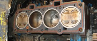
17. Check the flatness of the flange surface of the priora catalytic collector. To do this, place the ruler with its edge on the surface of the flange and measure the gap between the flange plane and the ruler with a feeler gauge. Grind the flange surface or replace the catalytic collector VAZ 2172 if the gap exceeds 0.1 mm. Helpful Hints To prevent the gasket from sticking and to improve its tightness, we recommend lubricating the gasket on both sides with a thin layer of graphite grease before installation. Lubricate the exhaust manifold mounting studs with graphite grease.
Review of the exhaust system of Lada Priora
The exhaust gas exhaust system on the Lada Priora performs the following functions:
- exhaust gas removal;
- noise reduction when the engine is running;
- neutralization of toxic hazardous substances in exhaust gases.
The basis of the Priora exhaust system includes:
- 1. Exhaust manifold with converter;
- 2. Resonator;
- 3. Main muffler;
- 4. Auxiliary muffler;
- 5. Connecting pipes.
The manifold is used to remove exhaust gases from the cylinders into the exhaust pipe. The tightness of the connections is ensured by sealing with a metal gasket in two layers between the block head and the exhaust manifold. The attachment of the exhaust manifold to the cylinder head on one side goes into connection with the converter on the other. The collector and converter connected into one unit make it possible to reduce the warm-up time to the operating temperature of the latter, which significantly increases the efficiency of the converter.
Installation of oxygen concentration sensors at the inlet and outlet of the converter ensures constant monitoring of the quality of exhaust gases. The connection between the intake pipe and the manifold has a heat-resistant seal in the form of a metal-asbestos gasket. And the metal compensator connecting the additional muffler with the exhaust pipe serves as a vibration damper from the engine to the body and the entire exhaust system.
The exhaust gas exhaust system is connected by attaching it to the body brackets using 4 rubber rings. On the main muffler, the suspension cushion has a reinforced structure, which is due to the increased load on it.
Restoring the tightness of the intake system on the editorial Kalina
Oil leaks through the joints of the intake pipe not only spoil the appearance of the engine compartment, but also affect the operation of the engine. However, you should not rush and immediately change the leaky element.
Even with a working crankcase ventilation system, a certain amount of oil will get into the intake manifold - as this system is commonly called in everyday life. There is nothing criminal about this. Over time, the tightness of its joints is broken and liquid can seep out. In addition to the aesthetic aspect, this is also reflected in the operation of the motor. Through the cracks not only oil presses, but also air leaks. Most often, this leads to uneven engine operation (slight tripping) at idle speed.
The tightness of the intake system is very important for the proper operation of the engine.
The tightness of the intake system is very important for the proper operation of the engine.
Oil traces at the manifold joints are visible to the naked eye, and air leaks can be calculated using a simple technique. While the engine is running, spray any suspicious areas with brake system or carburetor cleaner. If after some time the engine speed “floats” or it begins to choke altogether, then there is a significant suction in these places. The cleaner, as a flammable substance, entering the intake, enriches the air-fuel mixture, which causes the engine speed to fluctuate.
The intake of additional air, not taken into account by the sensors on the intake side, causes a constant leaning of the mixture. The control system tries to adjust the fuel supply based on the output readings of the front lambda probe. As a result, we have the notorious engine trim at idle speed.
Often, a decent amount of air leaking through the joints of the intake pipe even causes the Check Engine indication to appear. The corresponding error code will indicate that the air-fuel mixture is too lean. Other culprits for this problem are worn gaskets at the junction of the pipeline and the cylinder head.
What is a “spider” for Priora and what is it for?
Tuning the exhaust system of the Lada Priora includes replacing the exhaust manifold with a similar sports version, which is called the “spider”. The main difference between the original manifold and the spider is that the latter has a larger diameter and the same length of outlet pipes, which facilitates the rapid release of exhaust gases from the cylinders to the exhaust pipe.
This spider design prevents exhaust gases from flowing back into the combustion chamber, which increases engine power and performance. In addition, the manifold performs the function of purging the combustion chamber and filling it with a combustible mixture due to the pressure that is created when exhaust gases are released.
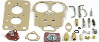
To tune the Priora exhaust system, a ready-made kit for installing a direct-flow Stinger exhaust with additional components that are perfectly attached to each other is often used. As a rule, the tuning kit includes the following parts:
- new muffler with nozzle;
- spider;
- resonator Stinger Sport with a pipe diameter of 51mm.
The need to install a “spider” on Priora arises when:
- long vehicle acceleration time;
- low engine power;
- failure of the old exhaust system, where installing a spider on a Priora is considered as an alternative to the old one.
On the tuning parts market there are many modifications of “spiders” made by different manufacturers. Some models are produced without oxygen sensors, which requires reflashing the electronic engine control unit.
There are spiders with long and short pipes, which are indicated by the corresponding numbers 4-2-1 and 4-1. These designations reflect the shape of the spider pipes, that is, 4 pipes merge into 2, and then into 1, in the second option, respectively, 4 pipes are immediately combined into one, which significantly reduces the length.
The most popular among car enthusiasts has become the long spider 4-2-1, which, unlike the short one, shows good results in a wide speed range. A short spider 4-1 is better suited for forced engines operating at 6-10 thousand rpm.
Removing the exhaust manifold on a Priora
27 Jan 2014
Repair No comments
Many motorists carry out small home repairs in their own garage. To carry out some repair work, it is necessary to remove the exhaust manifold on the Lada Priora .
To carry out the operation, you will need a 13″ socket wrench with an extension, and a flat-blade screwdriver. Before starting repair work, you need to make sure that the exhaust system of the vehicle is completely cooled down. If this does not happen during work, you may receive serious damage in the form of burns.
The sequence of work is as follows:
First, the pipe of the additional muffler, which is connected to the catalytic collector, is disconnected. To do this, you need to bend the edges of the plate and unscrew the fastening nuts. To do this, use a 13″ wrench with an additional extension. After this, the locking plate is removed. Once the locking plate is removed, the heat shield is removed. The flange of the muffler pipe is moved, after which the sealing gasket is removed from the studs of the catalyst manifold. After this, the blocks with contact wires are disconnected from the oxygen concentration control and diagnostic sensors installed on the catenary collector. To remove the exhaust manifold, you need to unscrew the two bolts that secure the exhaust manifold to the car engine cylinder block. For these purposes, a 13″ socket wrench is used. After the bolts are unscrewed, the catcollector bracket is removed.
To remove the collector, you need to unscrew the nut on the rear engine mount and loosen the bolt securing the engine mount to the car body. After this, you need to remove the bolt on the engine mount. The three nuts securing the support bracket to the cylinder head are unscrewed; a 13″ head is used for this purpose. After loosening the nuts, the bracket moves along the cylinder head studs.
The fastening nut on the supply pipe of the coolant supply pump is unscrewed. After loosening the fastening of the bracket to the pump pipe stud, the bracket is moved away from the cylinder head. The eight nuts securing the exhaust manifold are removed. For this purpose, a 13″ head is used. The exhaust manifold of the Lada Priora car moves along the cylinder head studs and is pulled down.
Advantages and disadvantages of installing a spider on a VAZ 2170
After installing the “spider” on the VAZ 2170, Priora owners note the following positive changes in its operation:
- the car accelerates faster;
- the maneuverability of the car on the road improves;
- the engine sound is reminiscent of a sports car engine;
- the engine becomes more powerful up to 10 hp;
However, often a change in the design of the exhaust system associated with the installation of a spider can also have negative consequences:
The nuts securing the catalytic collector to the Priora cylinder head are difficult to access. In addition, the collector flange is sealed with a metal-reinforced gasket. The sealing gasket must be replaced every time the connection is disassembled. Before removing the catalytic converter, it is necessary to remove the intake manifold - this will facilitate access to its mounting.
- 1. Remove the decorative engine cover (see “Removing and installing the decorative engine cover for the VAZ 2171”).
- 2. Remove the wire from the negative terminal of the battery.
- 3. Disconnect the exhaust pipe of the additional muffler from the catalytic collector by unscrewing the nuts securing the exhaust pipe flange to the catalytic collector flange and remove the exhaust pipe flange from the studs of the VAZ 2170 catalytic collector flange (see “Replacing the additional muffler”).
- 4. Remove the air filter (see “Removing and installing the air filter”).
5. Remove the air supply hose and three hoses of the crankcase ventilation system of the VAZ 2170 (see “Cleaning the crankcase ventilation system”).
6. Disconnect the four connectors of the ignition module wiring harness and move the harness to the side. Remove the ignition modules (see “Removing and installing ignition coils”).
7. Remove the throttle assembly.
8. Remove the intake manifold of the VAZ 2172 (see “Replacing the cylinder head cover gasket of the Lada Priora”).
9. Disconnect the wiring harness blocks of the control and diagnostic oxygen concentration sensors from the engine harness...
10. ...and disconnect the holders of the wiring harnesses of the control and diagnostic oxygen concentration sensors from the heat-insulating shield of the steering mechanism
11. Unscrew the three nuts securing the thermal insulation shield of the Lada Priora steering mechanism to the engine shield and remove the shield.
- 12. Unscrew the two nuts securing the water pump supply pipe bracket, unscrew the bolts securing the catalytic collector to its mounting bracket, unscrew the eight nuts securing the catalytic collector to the Priora cylinder head and remove the catalytic collector. Disconnecting the catenary collector from the cylinder head and troubleshooting it is described in detail in the subsection “Replacing the catenary collector gasket”.
- 13. Remove the sealing gasket of the catenary collector from the cylinder head studs.
- Be sure to replace the sealing gasket of the catalytic collector and inlet pipe with a new one every time you disassemble the connection.
- 14. Clean the flanges of the block head and catalytic collector from the remains of the old gasket and carbon deposits.
- 15. Unscrew both oxygen sensors from the VAZ 2171 catenary collector and install them on the new VAZ 2172 catenary collector.
- 16. Install the cathode collector and all removed parts and assemblies in the reverse order of removal.
To prevent the gasket from sticking and to improve its tightness, we recommend lubricating the gasket on both sides with a thin layer of graphite grease before installation.
Lubricate the mounting studs of the Priora exhaust manifold with graphite grease.
Sooner or later, the car needs to be repaired. In some places the replacement must be carried out as planned, in others it is not. But every car owner faces a similar problem.
The question immediately arises: what repairs can you realistically carry out on your own, and where do you need to go to a car service center? Thanks to the Internet, all the necessary information, even with video instructions, can be found quickly.
The main function of the manifold is to distribute air among the engine cylinders, and also mix the fuel-air mixture there. And if you do not diagnose the operation of the air system in a timely manner and do not pay attention to the symptoms, this can lead to more serious engine damage.
Removing the intake pipe
We remove the inlet pipeline to replace the sealing gaskets. in connecting the pipeline and the cylinder head, for removing the fuel rail, as well as when repairing the cylinder head. Disconnect the wire terminal from the negative terminal of the battery. Remove the plastic engine cover. Use a Phillips screwdriver to loosen the clamp securing the crankcase ventilation hose...
...and remove the hose from the cylinder head cover pipe.
Using a Phillips screwdriver, unscrew the self-tapping screw securing the guide tube of the oil level indicator to the intake pipe...
...and lift up the tube with the oil level indicator.
Using pliers, loosen the tightening of the band clamp securing the vacuum brake booster hose... ...and remove the hose from the intake manifold. Disconnect the end of the throttle drive cable from the drive sector (see “Replacing the throttle drive cable”). Having unscrewed the nuts securing the throttle assembly and without disconnecting the coolant hoses from it, remove the throttle assembly from the inlet pipeline (see “Removing the throttle assembly”). We disconnect the wire blocks from the ignition coils of the 1st, 2nd and 3rd cylinders (see “Checking the condition and replacing the spark plugs”)...
...and move the wiring harness to the side.
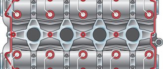
Using a 10mm socket, unscrew the two nuts of the upper fastening of the intake manifold to the cylinder head cover. Using a 13mm socket, unscrew the two bolts and three nuts of the lower fastening of the intake manifold.
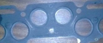
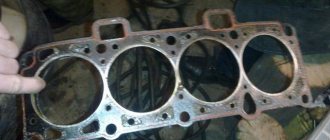
Places for attaching the intake manifold to the cylinder head
(for clarity, the intake pipeline and the fuel rail with injectors have been removed): 1 - studs; 2 - holes for bolts
Unfasten or cut the two clamps securing the engine management system wiring harness to the upper timing belt cover. Disconnect the engine control system wiring harness block from the phase sensor (see “Removing the phase sensor”). We remove the ignition coils of the first, second and third cylinders (see “Checking the condition and replacing spark plugs”). We close the holes for the ignition coils in the cylinder head cover with a rag.
We move the intake pipe forward (along the direction of the car) and lift it up, bringing it out from under the wiring harness of the engine control system.
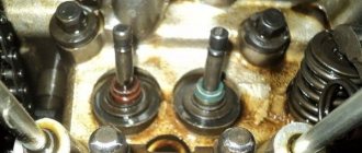
There are sealing rubber gaskets installed in the grooves of the intake manifold flange. If additional work is required after removing the intake manifold, it is necessary to cover the holes in the cylinder head with a rag to prevent objects from getting into the engine. Before installing the intake pipeline, check the condition of its sealing gaskets. If the gasket has lost elasticity or is damaged, it must be replaced with a new one. Install the intake pipe in reverse order. We tighten the bolts and nuts securing the intake manifold to the cylinder head to the prescribed torque (see “Appendices”).
Determining whether the engine is sucking in air
Before you start removing more than half the engine parts to get to the manifold, you should check other parts of the air system. And after that, carry out a complete tuning of the car. First of all, you need to inspect all the hoses and gaskets located on the cylinder block.
The most common method of finding air leaks is to spray the hoses with plain water; if there is a hole in one of them, the engine speed will decrease when water enters.
Detailed instructions for removing the intake manifold on a new Priora
It is necessary to remove parts from a cooled engine. It will take about an hour, provided that you have at least a little understanding of the injection system. The following sequence of actions must be followed:
- First of all, you need to remove the throttle. There is no need to completely remove it, just move the assembly connecting it to the manifold to the side. You also need to remove the throttle valve to thoroughly clean everything;
- disconnect the drive throttle cable from the manifold;
- disconnect the connectors from each other to remove the wires from the ignition coils;
- on the camshaft, disconnect the sensor wires;
- disconnect all canister wires;
- disconnect the brake booster vacuum hose going to the manifold;
- then unscrew the clamp and remove the ventilation pipe;
- Unscrew the self-tapping screw of the oil level indicator guide tube;
- remove the dipstick with the guide tube;
- using sockets and a ten-size wrench, unscrew the nuts and bolts securing the exhaust module and coils from cylinders 1-2-3;
- remove the coils;
- then you need to unscrew the collector fasteners;
- slide it forward and remove the manifold.
Exhaust manifold of engine 21124 (1.6i 16v) - removal and installation, gasket replacement
The 21124 engine has a steel exhaust manifold combined with a catalytic converter.
More details (see “Exhaust system”). 1. We prepare the car for work (see “Preparing the car for maintenance and repair”).
2. Remove the engine mudguard (see “Engine mudguard - removal and installation”).
3. Disconnect the vacuum brake booster hose from the inlet pipe (see “Intake pipe of engine 21124 (1.6i 16V) - removal and installation, replacement of o-rings”).
4. Remove the oxygen concentration sensor from the manifold (see “Oxygen concentration sensor - check and replacement”).
10 mm socket wrench
unscrew the upper nut.
. and two nuts for the lower mounting of the protective screen.
6. Remove the screen from the engine compartment.
13 mm socket wrench
Unscrew the two nuts securing the bracket clamping plate.
8. Remove the bar from the studs.
13 mm spanner
unscrew the two bolts securing the bracket to the cylinder block.
10. Remove the bracket from the engine compartment downwards.
Warning!
The following operation must be performed only in the order indicated below, otherwise the coolant pump pipe bracket may be bent
11. Disconnect the exhaust pipe from the additional muffler (see “Reception pipe of engine 21124 (1.6i 16V) - removal and installation”).
12. 13 mm
unscrew the lower and then the upper nuts of the bracket for the supply pipe of the coolant pump a few turns and move the bracket to the side (the photo shows the view from the partition of the engine compartment).
13. 13 mm
unscrew the eight nuts securing the exhaust manifold (three of them are not visible in the photo).
14. Remove the exhaust manifold complete with the exhaust pipe.
15. Remove the sealing gasket from the cylinder head studs.
16. Disconnect the exhaust pipe from the exhaust manifold (see “Reception pipe of engine 21124 (1.6i 16V) - removal and installation”).
17. Install the exhaust manifold in reverse order. We replace the gasket and damaged parts.