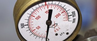
How to check the serviceability of the solenoid valve
Checking the EPH system of VAZ 2108, 2109, 21099 without special instruments Diagram of the carburetor solenoid valve control system
In the absence of a voltmeter and tachometer, a malfunction of the solenoid valve and control unit can be determined using a piece of insulated wire about a meter long. We perform troubleshooting using the method of elimination. If there is no idle speed, remove the wire tip from the solenoid valve terminal. Turn on the ignition without starting the engine. Connect the tip to the valve outlet. At the moment of connection, a click should be clearly audible. If this does not happen, you should check the serviceability of the solenoid valve. To do this, we again remove the wire tip from the valve terminal and, using a piece of wire, apply voltage to it directly from the “positive” terminal of the battery. If the valve operates with a characteristic click, it means that the control unit is faulty or there is no power supply to it. The connecting wires or their connectors may also be damaged. If the valve does not operate when voltage is applied, it should be replaced. When the engine is idling, you can verify that the solenoid valve is working properly. To do this, with the engine running, remove the wire tip from the valve terminal. If the valve is OK, the engine should stall. You can check the operation of the control unit using a known-good solenoid valve. To do this, turn on the ignition and put the tip of its wire on the valve terminal. With a working control unit, a characteristic click should be heard when the valve body closes to ground. It should be taken into account that using these methods it is impossible to verify the correct moment of turning on and off the EPH system. If the car is equipped with a tachometer, then the functioning of the system can be checked with sufficient accuracy using a test lamp instead of a voltmeter. For this purpose, a car lamp with a power of no more than 3 W and a voltage of 12 V, for example, an instrument backlight lamp, is suitable. We solder two pieces of insulated wire about 0.5 m long to its contacts. It is more convenient to use a lamp with a socket, then the wires are connected to the terminals of the socket. To check, connect a test lamp to the tip of the solenoid valve wire. We connect the output of the solenoid valve with a piece of wire to the “plus” terminal of the battery. The procedure for checking with a lamp is the same as when checking with a voltmeter. Using a test lamp, you can detect malfunctions in the tip of the “quantity” screw and its wire. To check, connect one wire of the test lamp to the tip of the screw wire, and the second to the “plus” terminal of the battery. When the throttle valve of the first chamber is closed, the lamp should be on, and when it is open, it should go out. In the same way, you can check the condition of the wire by removing its tip from the tip of the screw and connecting it to the carburetor body. Checking the EPH system using special instruments
Every year, cars with automatic transmission are becoming more and more popular. Many people choose automatic transmission for one simple reason – it’s convenient. But not everyone can afford a new car from a showroom. Therefore, many people prefer to buy used cars on the secondary market. Of course, such machines may have hidden problems. And today we will look at how to check automatic transmission solenoids for functionality.
Purpose and application of solenoid valves
Faulty vvti valve.
Where is the VVTI valve located and how to check it The solenoid valve acts as a regulating and shut-off device in the remote control of the transportation of flows of liquids, air, gas and other media. Moreover, the process of using it can be either manual or fully automated.
The most popular is the Esbe solenoid valve, which has a solenoid valve as its main device. The solenoid valve consists of electric magnets, which are also popularly called solenoids. In its design, the solenoid valve resembles an ordinary shut-off valve, but in this case, the position of the working element is controlled without the use of physical effort. The coil takes on the electrical voltage, thereby operating the solenoid valve and the entire system.
The solenoid valve works both in complex technological processes in production, or in public utilities, and in everyday life. Using such a device, we can independently regulate the volume of air or liquid supplied at a specific point in time. The vacuum valve can operate in rarefied air systems.
Depending on the conditions where the solenoid valve is used, the housing can be manufactured as normal or explosion-proof. This device is used primarily at oil and gas production points, as well as at automobile gas stations and fuel depots.
Water valves are used to automate water purification systems. In addition, the electromagnetic water valve has found its application in maintaining the water level in water tanks.
Valve device
The main structural elements of the solenoid valve are:
- frame;
- lid;
- membrane (or piston);
- spring;
- plunger;
- stock;
- an electric coil, also called a solenoid.
Valve design diagram
The body and cover can be made of metal materials (brass, cast iron, stainless steel) or polymer materials (polyethylene, polyvinyl chloride, polypropylene, nylon, etc.). To create plungers and rods, special magnetic materials are used. The coils must be hidden under a dust-proof and sealed housing in order to exclude external influence on the delicate operation of the solenoid. The coils are wound with enameled wire, which is made of electrical copper.
The device is connected to the pipeline using a threaded or flanged method. To connect the valve to the electrical network, use a plug. Heat-resistant rubber, rubber and silicone are used to make seals and gaskets.
The product is supplied with drives with an approximate operating voltage of 220V. Some companies carry out orders for the supply of drives with voltages of 12V and 24V. The drive is equipped with a built-in forced control circuit SFU.
Operating principle of electromagnetic systems
The electromagnetic inductor operates in all known AC and DC voltages (220V AC, 24 AC, 24 DC, 5 DC, etc.). The solenoids are placed in special housings protected from water. Due to the low energy consumption, especially for small electromagnetic systems, control using semiconductor circuits is possible.
The smaller the air gap between the stopper and the electromagnetic core, the more the magnetic field strength increases, regardless of the type and magnitude of the applied voltage. Electromagnetic systems with alternating current have a much larger rod size and magnetic field strength than systems with direct current.
When voltage is applied and the air gap is at its maximum extent, the AC system, consuming a large amount of energy, raises the rod and the gap closes. This increases the power of the output flow and creates a pressure drop. If direct current is supplied, then the increase in flow rate occurs rather slowly until the voltage value becomes fixed. For this reason, the valves can only regulate low pressure systems, except those equipped with small bores.
In other words, in a static position, provided that the coil is de-energized and the device is in the closed/open position (depending on the type), the piston is in a tight connection with the valve seat. When voltage is applied, the coil transmits an impulse to the actuator and the rod opens. This is possible because the coil generates a magnetic field, which in turn acts on the plunger and is drawn into it.
Gas water heater valve device
In order to make it easier for home craftsmen to restore the functionality of a gas boiler, in particular when there is a malfunction of the gas valve, we will consider the design of the unit and the technical nuances of diagnostics and repair.
But, if you do not have experience in disassembling geysers and relevant knowledge on the topic, then it is preferable to invite a specialist for repairs and maintenance.
A device called a gas solenoid valve performs an important function of a gas water heater - controlling the flow of the fuel component (natural gas). The picture below shows a common version of the design of the control unit, which includes the valve.
In fact, the control unit is a two-stage mechanism, the first stage of which is the gas solenoid valve (1). The second stage is a mechanical device that provides adjustment via a manual control rod (2).
The design of the gas valve is quite simple - it is made on the principle of an electromagnetic traction device, which are used as part of a wide variety of devices and instruments. If you dismantle this component from the control unit diagram, for which it is enough to unscrew a couple of screws, the valve part, which is attached to a spring-loaded metal rod, will appear before the eyes of the master.
As you can see from the picture, the design consists of a skirt body , which includes a valve part - a membrane and an electromagnetic module . The valve part is mounted on a metal rod , spring-loaded for the return stroke to the “closed” position.
When voltage is applied to the electromagnet coil, the metal rod moves upward under magnetic influence and moves the membrane away from the passage hole of the skirt. This opens the gas passage towards the manual valve and further to the burner.
About the types of products
Products are classified according to several parameters.
Based on the position of the locking element in the absence of voltage on the coil, the following are distinguished:
- Normally open, or BUT. The passage for liquid or gas is open, but when voltage is applied, it closes.
- Normally closed, or NC. The passage for the medium is blocked, and when voltage is applied it opens.
Some models are produced as universal ones, and normally the position of the locking element is adjusted during installation and connection to the control network. Such switched devices are called bistable.
Depending on the working environment, shut-off valves are produced for:
- Air.
- Water.
- Pair.
- Active media
- Fuels and lubricants.
Devices for working in radioactive environments are distinguished by a special selection of materials with increased radiation resistance. The vacuum solenoid valve must provide particularly high tightness
Water supply valve device
The inlet solenoid valve of a household washing unit is a small device consisting of:
- housings;
- electromagnetic coil with core;
- springs;
- a disk mounted on a core that blocks the flow of water coming from the water supply.
The body material in most cases is various types of heat-resistant polymer materials, less often brass or stainless steel. For the manufacture of membranes, gaskets and seals, heat-resistant rubber, caoutchouc, fluoroplastic or silicone are used. Electric magnets with rigidly fixed parts (solenoids) are installed in the retractor coil. Depending on the number of solenoids, they can be one, two, or three-coil. The number of coils corresponds to the number of sections of the device through which tap water flows into the dispenser. Electromagnetic valves of washing machines from different companies may differ in materials of manufacture, appearance or number of coils, but the operating principle of all such elements is the same.
Solenoid: how to check and why this element fails
So, the operation of the automatic transmission solenoids is controlled by the automatic transmission ECU. The control unit constantly sends pulse signals of a certain frequency to the valve. In simple words, the solenoid actually controls the oil pressure, which, in turn, is the working fluid in the machine device.
- Simply put, a solenoid is a device where a metal rod is wrapped in a spiral through which direct current flows. The rod in the housing is movable when a current acts on the spiral, this causes the rod to move from the end of the spiral to its beginning.
Also in the device of such a solenoid (electrovalve) there is a spring, which forcefully returns the rod to a given position. Without going into too much detail, the job of the solenoid is to close or open a passage for transmission oil.
The solenoids are located in the valve body (hydraulic valve plate, automatic transmission valve block) and are inserted into the channel, secured with a bolt and a pressure spring. Also connected to the solenoid is a cable or wiring connector for connection to the control unit (automatic transmission ECU).
- Please note that often problems in automatic transmission operation are associated with wiring failure, that is, the ECU simply loses connection with the valve and the automatic transmission cannot operate normally. It is also not uncommon for the solenoid itself to fail. When checking, it is important to consider what type of device is used on a particular automatic transmission, since there are several types of solenoids.
Types of gearbox solenoids - automatic
If the first solenoids worked on the “open/close” principle, then the device later evolved, turning into a hydraulic valve. In short, control solenoids can be ball and spool (they have a valve - a spool).
Water supply valve device
The inlet solenoid valve of a household washing unit is a small device consisting of:
- housings;
- electromagnetic coil with core;
- springs;
- a disk mounted on a core that blocks the flow of water coming from the water supply.
The body material in most cases is various types of heat-resistant polymer materials, less often brass or stainless steel. For the manufacture of membranes, gaskets and seals, heat-resistant rubber, caoutchouc, fluoroplastic or silicone are used. Electric magnets with rigidly fixed parts (solenoids) are installed in the retractor coil. Depending on the number of solenoids, they can be one, two, or three-coil. The number of coils corresponds to the number of sections of the device through which tap water flows into the dispenser. Electromagnetic valves of washing machines from different companies may differ in materials of manufacture, appearance or number of coils, but the operating principle of all such elements is the same.
Malfunctions of inlet valves and their replacement
If the washing unit has been idle for a long time and tap water has accumulated in the washing drum, the inlet valve most likely needs to be replaced. If the washing unit, for some reason, was left in a room with sub-zero temperatures, then due to the freezing of the water accumulated in it, the body of the device may crack. In this case, it is also changed entirely.
If the water supply is poor, sometimes it is enough to clean the filtration mesh to restore operation. To do this, you need to turn off the water and remove the water supply hose and remove the contamination by pulling out the mesh with pliers and then putting it in place.
The main malfunction of solenoid valves is a malfunction of the electromagnetic coil. If the coil is burnt out and does not retract the rod, water does not flow into the washing tank at all. Most modern units are equipped with electric valves that have a non-separable design, so they cannot be repaired. It is better to carry out replacement with the assistance of a specialist. You can carry out the repair yourself by purchasing a new filling electric valve, similar to the one that failed. To do this you need:
- turn off the power to the washing unit;
- turn off the water supply and disconnect the water supply hose;
- remove the lid or side wall (for top-loading machines) of the washing machine;
- disconnect the electrical wiring and hose (or hoses) associated with the dispenser section;
- unscrew the fixing plate bolts;
- remove the device;
- check performance using a multimmmeter. The winding of a single-coil valve should “ring” at 3.8 kOhm (on older Samsung models 4.5 kOhm), for double and triple coils this figure ranges from 2 to 4 kOhm;
- Replace the solenoid valve with a new one, reassembling it in the reverse order.
Principle of operation
The design of the anti-siphon valve is not complicated. The principle of its operation is based on the following effect. A spring or ball type valve is placed in a specially designed tube. Next, it is installed on the drain system hose, sink siphon or drain. During the drain program, the flow of waste water, enhanced by pressure, easily passes through it and is sent to the sewer.
In the event of a siphon effect, namely the return of dirty water, the valve reliably closes the hose and prevents it from entering the tank.
In other words, liquid is easily removed from the drum of the washing machine and passes through the valve without hindrance, but its return is no longer possible. Spring anti-siphons achieve this using a rubber membrane and a steel spring that closes the drain. In a ball-type valve, this function is performed by a ball made of soft material.
Replacement
- After turning off the power to the equipment, turning off the water supply to the machine and removing the required wall of the device, you need to disconnect the hoses and terminals from the valve.
- Be sure to remember how they were located, and even better, take a photo.
- Next, you need to unscrew the bolts holding the part or remove the latches (in some models they secure the valve).
- By turning the valve, it is removed, after which a new inlet valve is inserted in its place.
- The new part should be secured in the reverse order.
- When the inlet valve is in place, you need to turn on the machine and check whether it has started to take in water.
You can see the process of replacing the water inlet valve on an LG washing machine in the following video.
INDESIT WITL 86 "vertical" age about 7 years. The washing machine suddenly began to fill with water uncontrollably. And with washed things and empty! And since we supply water according to time(, we need to find out who is to blame: the valve or the electronics. While there is no water, turn off the tap on the supply pipe. They gave water, opened the tap - thin streams ran from the holes for flushing the powder (the washing machine was unplugged from the outlet ). Result: “the valve does not hold.” Internet monitoring did not please: “INDESIT WITL 86 WATER SUPPLY VALVE 33390017” price from 800 to 2400 rubles! Plus delivery time. ((((Knowing the quality of our water) I hope there may be dirt (although filter - the coarse cleaning flask is worth everything) or the frog might get stuck).Just in case, I reached into the pumping pump - I earned 1 iron ruble))
Disassembling the machine. It's enough to shoot the left side and that's it, but then it's a bit cramped, you need to have the hands of a surgeon)).
Disconnect and remove the panel with switches (so as not to interfere) Lift the top part up. I didn’t remove it completely - there was too much extra, factory installation, etc...
Disconnect, otherwise you cannot pull out the valve:
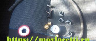
1. thick corrugated hose in the center. 2. plugs (2 pcs.) on the valves. 3. spring clamps (2 pcs) on the hoses (all motorists love them)) but it will not be easy to compress them. I used duckbill pliers. 4. remove 2 rubber water supply tubes.
Removing the double valve.
1 - press (with a thick screwdriver one at a time) 2 - turn until the latches disengage. Pull out the water supply valve
Checking valves. Measure the resistance of the electromagnet coils. I got a coil resistance of 3.72-3.77 kOhm. The windings are intact. (from 3 to 5 kOhm) If you blow into the holes, you can hear the characteristic gurgling sounds of passing air. Result: the valve does not hold. Replacement. Nope.
Disassembling valves 1. pry off the coil with a screwdriver.
2. pull out the valve. Unscrew the middle part. Unscrew by pushing with a screwdriver or “platypus”.
Wipe everything away from plaque. Clean the 3 pressure equalization holes.
3. I greased everything lightly with silicone. I don't think it will get any worse.
Design, replacement and selection of the water supply valve for a washing machine
Washing clothes is impossible without water supply; in any washing machine, this function is performed by a water supply solenoid valve, which regulates the water level in the tank during washing and rinsing. With a seemingly large variety of washing machine models, all fill valves in washing machines have a very similar design and can be interchangeable
Inlet valve device
The professional name of the valve is KEN, which stands for electromagnetic filling valve. This gives us an understanding that the operation of such a valve is based on electromagnetic forces. An electric current passing through the coil (1) of the valve creates a magnetic field that draws in the core (2), which opens a small hole in the valve body, water entering through this hole lifts the main membrane, opening the water flow freely into a container with powder or detergent, from which the soap solution already enters the drum.
Depending on the design of a particular model, there are valves with 1,2,3 and even 4 coils, but most often, of course, with two coils. The number of coils is necessary to direct the water in the right direction to rinse out either the laundry detergent, fabric softener or fabric softener.
An important feature of any water supply fill valve in a washing machine is the angle between the water inlet, where the inlet hose from the water supply is connected, and the outlet, where the hose is connected to the powder receptacle hopper.
Another feature of the valves is the outer diameter of the outlet, here manufacturers have not come to a common denominator and can fantasize from 8 to 12 mm, respectively, a hose with an inner diameter of 8 mm will not fit on a 12 mm outlet, but rather will leak.
How to check KEN
To check the filling valve, you need to use a multimeter and a probe, by which we mean a wire with a plug at one end and a connector for connecting the valve at the other. Before applying voltage to the valve for testing, you need to turn off the water and disconnect the washing machine from the network, and most importantly, first check with a multimeter and only then apply voltage.
To check with a multimeter, you need to switch it to the position measuring resistance in kilo-ohms, not continuity, but measuring resistance. Since the resistance of the CEN coil is more than 1000 ohms, the multimeter will not “beep” in the “dialing” mode
After checking the serviceability of the coil, you can proceed to checking the valve itself, to do this you need to apply voltage to the coil and the valve should begin to let water through; when the voltage is turned off, the water supply stops completely
Replacing the filling valve
To replace the filling valve, you need to unscrew the top cover
How to choose a valve
Repair of water intake valves
Filling valves
Electromagnetic filling valves for supplying water to a washing machine come in several types, from single to triple, and they are also divided according to the location of the contacts and their type.
Happy day everyone. Overall a good evening.
In winter, I started to float XX (went up to 2000 and dropped to 550), stalled at a traffic light, I had to press on two pedals so as not to stall. I came to knowledgeable people, they removed and cleaned the BDZ + KXX. A few drops of water were removed from the CXX, or rather from the insides of the electromagnet, a small amount of ice was removed from the air duct, in the tube that discharges crankcase gases into the air duct, drops of water were also removed + washed from the emulsion. This action didn’t save me for long; with the warming it somehow went away, so I thought it was a seasonal problem.
DIY water solenoid valve installation
Before proceeding with installation, you must determine the type of connection. The most commonly used are:
- Threaded. The inlet and outlet pipes are equipped with external or internal threads; through the corresponding fittings, the fittings are built into the pipeline gap. The most convenient for self-installation, it is better to choose this type of connection.
- Flanged. The pipes are equipped with flanges; the ends of the pipes must also have flanges of the appropriate standard size; they are tightened together with bolts. They provide high pressure and flow intensity, often used on high and medium pressure lines.
Before installing the device, a number of preparatory operations should be performed. Pipes must be marked, cut to size and cleaned. The location for installing the electromagnetic device must provide free access to the device for its installation, maintenance and repair. Experienced professionals also formulated several recommendations:
- All work on installing or removing the device can only be carried out when disconnected from the network.
- The pipeline system must be supplemented with a mechanical cleaning filter. This will prevent contamination and damage to parts by foreign matter such as sand, rust flakes and lime deposits.
- The device body should not bear the weight of the pipeline section.
- The device should be connected in accordance with the arrows marked on the housing. They indicate the direction of flow.
- When installed outdoors, the valve should be protected from exposure to natural phenomena. A waterproof casing is usually sufficient. When working in low temperature conditions, the casing must be heated.
- Threaded connections must be sealed with FUM tape or plumbing thread.
- The cable for connecting to the control system should be copper. It must have a sufficient cross-section of at least 2 mm 2.
The selection of a specific model is carried out based on calculations of the parameters of the pipeline system.
The pressure, pipe cross-section, required response speed and characteristics of the controlled medium should be taken into account.
Valve check
Checking the solenoid valve for correct operation can be done in three different modes:
- when the engine is idling;
- when braking the engine;
- after turning off the ignition.
The general serviceability of the valve can be checked after turning on the ignition. To do this, you need to increase the engine idle speed to 2100 RPM. After crossing this mark, a characteristic click should be heard, which means that the valve has closed. After this, you can lower the speed, as soon as its number reaches 1900 RPM, a click should be heard again, meaning that the valve has opened.
When braking with the engine while the gear remains engaged, the valve should not open, even if the engine speed has dropped below 1900 RPM. If a click is heard at this moment, the valve is not working properly.
If detonation and vibration occur after the engine ignition is turned off, this means that the valve does not close the idle jet and the fuel mixture enters the engine, which also indicates a malfunction of the solenoid valve.
You can also simply check the valve by disconnecting the power cable with the engine running. The motor should stop immediately after disconnecting.
You can check the valve by completely disconnecting the device from the carburetor. After dismantling the valve, you can connect it to the battery, after which you should hear a click and the valve needle should retract into the device. After turning off the power, you should hear a click again and the needle should move out.
The problem with the solenoid valve may lie not only in its malfunction, but also in the electronic control unit and in the wires. You can check the functionality of the wire using a multimeter (12 V ± 10%).
Checking the functionality of the control unit will require connecting the valve to the battery using an additional wire. A standard voltage control light is also required. First you need to disconnect the supply wire from the valve and connect it to the positive terminal of the battery. An additional wire is also connected to the battery positive. After this, you need to start the engine, at the cut-off of 900 RPM the warning lamp should light up, after reaching 2100 RPM it should go out. When it drops to 1900 RPM, it lights up again. If these indicators are met, but the engine stalls at idle, then the fault is probably in the valve control unit.
Let's sum it up
As you can see, the solenoid is an important element in the automatic transmission design. In this case, failure of the specified valve body valves disrupts the operation of the entire automatic transmission. Often, the main problem is natural wear of the solenoids or their contamination.
Also, in some cases, it is recommended to flush the valve body and/or automatic transmission before changing the oil if signs and symptoms of persistent contaminants and deposits are already noticeable.
Why the automatic transmission kicks, the automatic transmission jerks when changing gears, jerks, jerks and impacts occur in the automatic transmission: the main reasons.
What is an automatic transmission brake band: the purpose of the element and its features. Signs that your brake band needs adjustment and how to adjust it.
Signs of a malfunctioning carburetor solenoid valve
The purpose of the idle speed economizer, as well as all its modifications, is to forcefully shut off the flow of fuel to the engine cylinders through the idle speed system during carburetor braking (when inertial movement occurs with the gear engaged and the gas pedal fully released).
The economizer prevents fuel from entering the engine from the moment the engine is stopped, preventing its operation when the ignition is turned off.
Manifestations of EPHH malfunction
- Absence or instability of idle speed. The engine stalls or there are interruptions in its operation.
- The engine stalls when braking.
- The engine stalls when the gas is suddenly released at high speeds (from 2000).
- After the ignition has stopped and turned off, flashes occur in the cylinders.
About malfunctions of automatic transmission solenoids and their repair
A faulty solenoid is one of the main reasons for incorrect operation and the automatic transmission going into emergency mode. Despite the high reliability of modern valve body valves, by their nature these devices are consumables and therefore require periodic replacement. If the situation is not too advanced, the problem can be solved by simply changing the automatic transmission oil . It is quite possible to change the solenoid yourself, but first of all it is important to diagnose its malfunction.
To check any hydraulic block plate valve, you will have to “test” it. This is necessary for one simple reason: a faulty solenoid loses its normal resistance; to be more precise, it increases. How to check the solenoid? Very simple, the procedure for diagnosing valves is not complicated and consists of performing the following operations:
- Remove the hydraulic unit from the box, which is often located on the bottom of the unit, less often on the side;
- Disconnect the contacts of each solenoid from the corresponding connectors of the control unit;
- Ring each valve. The standard of resistance on horse skates is determined for each type individually. So, for example, for EV-1 solenoids, the resistance standard is in the range of 65-66 Ohms (at 20 degrees Celsius). For other valves, the normal values are different.
Note! Modern boxes have self-diagnosis functions, so to determine which solenoid is faulty, just connect to the car’s on-board computer. If such a measure is not possible, then you will have to carry out diagnostics using a traditional “diagnosis” with your own hands, and then repair the required element of the assembly.
Let's say a faulty valve is identified - what is required next? Naturally, repair the solenoid or their group. Unfortunately, it is not possible to disassemble the valve, wash it and put it back together; you will have to completely replace the valve body element. Its cost is not particularly high, so you should not be afraid of the repair procedure. Often, replacing solenoids in an automatic transmission is carried out as follows:
- The valve body is removed from the box;
- All connectors are disconnected from the valve;
- Unscrew the solenoid fastenings and it is removed from the valve body;
- After this, a new one is installed in place of the old valve, all connectors are connected to it;
- Then the valve body is installed back on the gearbox. The renovation is complete.
As you can see, there are no particular difficulties in the design of machine solenoids and their repair. The material presented today will help you understand both. We hope it was useful to you and provided answers to your questions. Good luck on the roads and in car repairs!
Tips for checking the thermocouple
If the user does not want to remove the TP from the boiler prematurely, then it can be tested on existing equipment. To do this, disconnect the TP tube from the automation system and connect a multimeter. While holding down the shut-off valve key, ignite the ignition device and after 30–40 seconds. take voltage readings from the primary sensor.
The advantage of this method is the simplicity of measurements, but the disadvantage is the lack of visual inspection of the sensor and the impossibility of cleaning its surface from soot, which can also cause emergency operation of the boiler.
In general, thermocouples are considered to be less accurate and sensitive temperature sensors than, for example, thermistors. But due to their low cost and high reliability, these thermocouples have been successfully used in heating processes for decades.
Despite the fact that the design of the thermocouple is quite simple, it is considered an extremely important element of modern protection of gas equipment. Acting as a primary temperature meter in the gas control system, the thermocouple creates reliable protection of gas equipment from possible emergency situations. The performance of a thermocouple is the key to safety in the home and can be monitored using simple measurements taken with a multimeter.
How to test a thermocouple using a multimeter
In private houses and apartments where gas is installed, in addition to kitchen stoves, gas boilers are often found to provide hot water supply and heating. Most heating and household gas appliances have a thermocouple in their design, which protects the device from overheating, which in turn ensures the safe operation of such equipment.
What is a thermocouple?
The thermocouple design includes two dissimilar conductors that are in direct contact with each other at one or more points (in rare cases, they are connected by compensation wires). When a temperature change occurs in the sensor area, voltage is created inside the device.
This ensures temperature control and overheating protection. Thermocouples can also be used to convert thermal energy into other types of energy, including electric current.
The main characteristics of a thermoelectric converter directly depend on the material from which they are made. Any temperature sensor made from two different metals will produce an electrical potential when exposed to temperature, but the response temperature will be different for each combination of metals. Due to this, thermocouples differ in their level of temperature control.
There are many types of thermostats, but their resistance to corrosion will be important. In those models of thermoelectric converters where the temperature sensor is located at a sufficient distance from the measuring device, expansion wiring is used in the design to connect them, thereby reducing the cost of the device.
Most thermocouples are standardized during production to a temperature standard of 0 degrees Celsius. Most manufacturers use electronic cold solder compensation technologies, which correct temperature differences at the device terminals.
Also, due to special electrical engineering, it is possible to minimize the deviation of other characteristics, which makes thermocouples more accurate and measurements as close to reality as possible.
Thermoelectric converters have become widespread in both household and industrial heating equipment. These simple yet useful devices can be found in the design of geyser, kitchen stove, industrial furnace, exhaust gas turbine, diesel engine, etc.
Possible problems with EPHH
The solenoid valve is a quite good car component in terms of operation. It doesn’t experience particularly frequent breakdowns, but it can’t be called an “uninterrupted worker” either. Due to the fact that in the post-Soviet space, electromagnetic valves of Solex carburetors and DAAZ carburetors are most often used, let’s look at typical EPHH problems using their example. In general, the list of frequently encountered unit failures is as follows:
All of the above breakdowns have one pronounced symptom, or rather, a complete or partial lack of stability in the idle speed of the car. If such problems happen to you, then, first of all, you should check the solenoid valve and its control unit, and only then the main idle jets and other components of the carburetor.
Operating principle of electromagnetic systems
The operating principle of the electromagnetic shut-off valve is based on the physical phenomenon of electromagnetic induction. When current flows through an inductor, a magnetic field arises inside it, acting on a core of magnetic materials with a force applied in the longitudinal direction. This force, depending on the polarity of the applied voltage, tries to pull the core inside the coil or push it out. In this case, the shutter element opens or closes.
Solenoid valve coils can operate on either 5 to 36 volt DC or 220 V AC.
Devices with low control voltage have low power and limited force transmitted to the locking element. This allows the use of low-voltage semiconductor circuits to control them. Such devices are used in low pressure systems of the working medium, on pipelines of small diameters.
Mechanical repair of ODE solenoid valve
Mechanical malfunctions of this device may include the following:
- The inlet filter mesh is clogged (for models operating with liquid). The valve must be removed and the filter washed.
- The seal of the plunger (piston, membrane) is worn out. In the case of an indirect-acting valve and wear of the plunger seal (and not the membrane), this valve will not block the flow of the working medium at all, since the pressure in the above-membrane cavity will always be lower than in the sub-membrane cavity and the membrane will not block the channel. You can verify that the seal needs to be replaced as follows (for a normally closed liquid valve). Disconnect the valve output from the network and supply liquid to the inlet. The valve should hold it. Otherwise, it is necessary to disassemble it and replace the seal. For a normally closed valve, a control voltage must first be applied to the coil.
- Spring breakage. The valve does not shut off liquid (gas) - for a normally closed type. Or it does not open the passage - for the normally open type. The valve must be disassembled and the spring replaced.
Signs that a check is needed
If difficulties arise with starting the engine and in a number of other situations, it is necessary to be able to check the functionality of the starting enrichment. Thoughts about a malfunction of the solenoid valve may arise in different cases.
Let's take a closer look at the main reasons:
- the first morning start of a cold scooter engine is problematic;
- it is difficult to start a cooled scooter engine after a long stay;
- fuel consumption significantly exceeds the consumption indicated in the passport;
- The scooter's power unit is quite unstable at idle;
- a warm engine does not maintain speed, and a cold engine functions intermittently.
Any of these problems should make the scooter owner think about a possible malfunction of the solenoid valve.
A faulty enrichment device can be in two positions:
- with the solenoid valve needle constantly extended;
- in the initial state, when the needle does not protrude.
It is necessary to be able to check the performance of the starting enrichment unit if difficulties arise with starting the engine
Each case has a different effect on the operation of the motor. The first situation makes it difficult to start the engine of a cold scooter. An attempt to start the engine by pressing the kickstarter, as well as starting with an electric starter, are unsuccessful. In the second case, the engine starts without problems, but during operation it consumes an increased amount of gasoline. Increased fuel consumption is associated with engine operation on a highly enriched mixture.
How to check the solenoid valve on a scooter
Let's try to figure out how to check the solenoid valve on a scooter or moped.
This is a simple operation. Let's start in order:
- You should check whether the enrichment channel is closed by the solenoid valve needle. Start the cold engine and observe the change in idle speed. At first they are increased and then decreased to the desired frequency. In this case, you can make a conclusion about the serviceability of the starting enrichment and not search for its faults;
- If the scooter starts without problems, but the engine speed does not decrease after reaching operating temperature and remains high, there is a high probability that the starting enrichment is faulty. In this case, it is necessary to check the functionality of the solenoid valve;
Checking the solenoid valve on a scooter
- If the power unit can be started only after long and exhausting presses on the kickstarter, the carburetor is not clogged, the gasoline level in the float chamber is set correctly, and the compression has not dropped, then most likely there are problems with the operation of the starting enrichment, and it needs to be checked.
So, we have come close to testing the scooter's starting enrichment for operability. To perform this operation, it is necessary to disconnect the wires connecting the solenoid valve to the scooter's electrical network. Then you should unscrew the fastening of the solenoid valve to the carburetor body and remove it. Next, you will need to prepare a pair of insulated wires, the length of which will allow you to connect the terminals of the starting enrichment to the battery.
When connecting, there is no need to observe polarity, since the solenoid valve is powered from an alternating voltage network. It is important to pay attention that the ends of the wires freed from insulation do not touch each other. All that remains is to connect the wires to the chips and supply 12 volts from the battery to the enrichment unit.
With a working enrichment device, after a couple of minutes you can see the needle gradually moving out of the device body. The amount of stroke can be determined by measuring the extension of the rod before applying voltage and after turning off the power. For a faulty solenoid valve, five minutes after connecting to the battery, the needle will remain in the same position. If there are no defects in the wiring, then we can conclude that the enrichment unit is faulty.
Don’t be upset and try to repair the solenoid valve - the cost of a new one, depending on the model of the moped, varies between 5-7 dollars. When purchasing, it is advisable to have an old starting enrichment with you or clearly find out from the seller whether the spare parts he offers correspond to the brand of the scooter.
A valve with an electromagnetic drive is a modern type of shut-off valve. They allow remote control of liquid or gas flows in pipeline systems. Such valves are well integrated into automated process control systems, save scarce human resources and make the operation of enterprises safer. There are a large number of different types of valves for different environments; they differ in their design and purpose.
Progress
Some users are interested in: how to remove, disassemble and repair the solenoid valve of a washing machine. The fact is that this element is non-separable, only changing the coils is possible.
But it is still recommended to perform a complete replacement. To do this, you will have to purchase an element that matches the make and model of your washing machine.
- Screw the valve to the body with the bolt that held it in place previously.
- Connect the wiring connectors to their places. It would be good if you marked or photographed the wires before disconnecting them.
- Connect the hoses to the appropriate sections. Secure the clamps.
- Replace the top cover. Secure it with screws.
The solenoid valve has been replaced. All that remains is to put the filter mesh in place and connect the intake hose. After connecting the SM to the network, start the wash and check the operation.
For those who are just about to start repairs, a video on the topic:
Spark plugs. The formation of deposits on them leads to the production of a weak spark, resulting in poor ignition of the flammable mixture.
- High voltage wiring. It supplies the spark plugs with the highest voltage from the ignition module. If the wires are faulty, the voltage may be insufficient or unstable, which also does not have the best effect on sparking and subsequent ignition in the combustion chamber.
- Ignition module. This unit accumulates electronic current and sends it to the spark plugs via high-voltage wiring. If the module loses its ability to accumulate or transmit voltage, then interruptions in the operation of the power plant occur.
Connecting a solenoid valve to a garden watering system
For a small garden, a -12 volt solenoid valve for irrigation (NT8048) is better suited. It is safe because if water gets on the contacts or if you touch it with wet hands, there will be no electric shock. The ability to connect it to a 15 Ah battery allows you to work without recharging for a week. It will also be easy to supply power from the shield via an AC adapter.
The water supply is provided from a storage tank installed at a height of at least 2 m. The water in it is drawn from a centralized system. Filling is controlled by a float sensor connected to a plug valve. The absence of a pump eliminates many problems. Watering the garden by gravity occurs within a few hours and does not need to be controlled. All irrigation control will be taken over by an electronic timer connected to the outlet.
The valve is installed in the pressure line of the irrigation system. The electromagnet coil is connected to the output of the adapter via a cable using terminals. They can be sealed on top with sealant to protect them from water.
The entire device can be conveniently placed in a utility room where you can install an outlet. A timer, adapter and electromagnet coil are connected in series to it. All that remains is to configure the watering mode. The time is chosen in the morning and evening so that there is a minimum of evaporation and the plants do not get sunburned. The duration of watering is set, which is then selected experimentally.
Watering should be different for different types of plants. The system can be gradually improved by adding new valves. You can connect your own timer to each of them or install a common microcontroller, setting the irrigation program.
Valves from old washing machines can be installed on the outlet pipelines, which will allow you to save a lot on the cost of the irrigation system.