In what cases is it necessary to change the cylinder head gasket on a Niva?
In principle, the element of the main cylinder block in question does not have a certain resource, that is, the gasket is replaced when it is damaged, which, however, usually occurs after 60,000 or 80,000 km. A breakdown is indicated by:
- air entering the antifreeze circulation system;
- lack of operating pressure in the combustion chamber of the air-fuel mixture;
- the presence of coolant in the lubricant or, conversely, the latter in the antifreeze (an oil film appears in the expansion tank).
All these problems lead to unstable operation of the Chevrolet engine.
In these situations, the gasket must be replaced immediately.
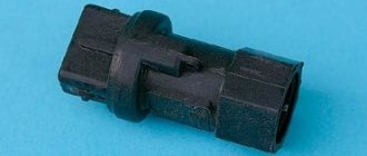
Device design
This element in the design is responsible for such basic functions as:
- Supplies the hot mixture into the cylinder
- Based on the gas distribution mechanism
- Removes exhaust gases
- It burns flammable mixtures and compacts
- Oil is drained and supplied, which normalizes the normal operation of the timing belt.
This design is made of aluminum alloy, and is presented in the form of a rectangular shape. It includes:
Replacing the gasket - what the Niva owner will need
To replace a cylinder head gasket that has lost its performance properties on a Chevrolet, you should prepare a set of tools and materials. Here is the list:
- flat and Phillips screwdrivers;
- pliers;
- wrenches – torque wrenches, as well as sets of open-end and socket wrenches;
- wrench with extension and heads for it (including one 13th type E-Torx);
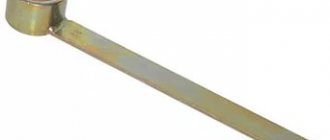
- 38 mm ratchet wrench.
You will also need:
- new gasket;
- neutral sealant;
- fresh antifreeze;
- sandpaper 180;
- New lock washer for Chevrolet camshaft.
The replacement work is carried out in several stages. Each is described below.
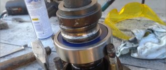
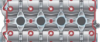
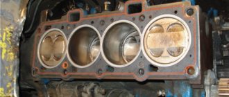
Block plane and broken gasket
A “punched” cylinder head gasket on Nivas and Shnivas is a birth defect. At some point they just went en masse. There is no need to be surprised. With modifications to the engine to meet new environmental standards, the designers are pushing the fan operating temperature further and further. This gives us an element of “glow” ignition. At a mileage of 15-25 thousand, the cylinder head gasket breaks, and so on down the list. Antifreeze to oil, oil to antifreeze. What do they do in the Papuan service? They buy a Fritex metal bag, install it, and 10 thousand later the client comes back with a new one, with the same question. Or rather, with two. How long? And the classic “what should I do?” It is not the Niva cylinder head gaskets or bolts that are to blame, it is the factory quality of processing of the block plane and the cylinder head plane that is to blame. Below I publish a photo of one of the blocks. I personally changed the gasket on it twice until I found the optimal set, which I now recommend. The metal bag does not help, but rather hinders. It cannot be crimped and does not fill uneven surfaces of the block. You need a shrink gasket that will completely accept the topography of the surface and the bolts that will constantly press it. This is the reason why hardened bolts are not rolled here. For a long time, the plant installed the Yaroslavl metal package “Fritex”, and now they have switched again to shrink gaskets. In a decent production facility, it would be easier to update the machine park and equipment, but at AvtoTAZ it turned out to be easier to go back ten steps along the road of technical progress.
Draining antifreeze in Chevrolet
This is the first stage that is performed when replacing a damaged Niva gasket. Initially, you need to remove the mudguard and the lubrication sump housing - they are located in the engine compartment.
Further:
- reduce the pressure in the coolant supply system by opening the cap of the distribution tank (be sure to close it afterwards - this will reduce the antifreeze pressure);
- place a container of at least 9 liters under the drain (it is under the radiator on the left);
- unscrew the cap and wait until the liquid pours out;
- inspect the gasket of the drain plug - if it is worn out, replace it too;
- Remove the cap from the expansion tank again.
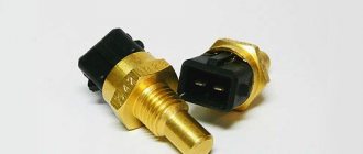
Now you need to get rid of the antifreeze remaining in the cooling system of the engine itself. To the left of the cylinder head, near the ignition unit, there is a separate drain hole. Place a container under it and unscrew the plug with a 13 key.
When the liquid flows out, tighten the radiator cap and cylinder head. In the latter case, a force of at least 25 N∙m will be required.
axel-roman › Blog › Tightening torques. Chevrolet Niva.
Tightening torque table for Chevrolet Niva 2123. If you don’t have the book, you can look it up here.
Tightening torques for cylinder head, engine, gearbox, transfer case, axles and brake system. Why do you need a wide torque range?
Because all dynamo keys have an error. It is better to take the moment in the middle of the range. Minimum permissible - maximum tightening torque. For example: 100-110 Nm.
Reminder:
In places where there are many tightening points, for example, the intake manifold. It is better to go through the final moment several times. The dots in the middle “sag.”
List of tightening torques (table):
— Cylinder head bolt (cylinder head). M12×1.25.
Clean the threaded holes from oil.
Degrease surfaces.
If the length of the bolt shaft exceeds 117 mm, it should be replaced with a new one. A non-shrinkable metal-reinforced gasket is installed between the block and the head. Reuse of the gasket is not permitted.
To ensure a reliable seal and avoid tightening the bolts during vehicle maintenance, we tighten them in four steps:
1st step - tighten bolts 1–10 to a torque of 20 Nm; 2nd step - tighten bolts 1–10 to a torque of 70–86 Nm, and bolt 11 to a torque of 31–39 Nm. 3rd step - then turn bolts 1–10 by 90°; 4th move - and another 90°;
It is advisable to use a rotation scale.
— Hydraulic support of the valve lever. (Hydraulic compensator) М24×1.5 15–20 Nm — Camshaft sprocket mounting bolt. M10×1.25. 41–51 Nm — Nut securing the camshaft bearing housing. M8. 18–23 Nm
Apply a thin layer of engine oil to the camshaft cams and journals, bearing housing beds and working surfaces of the valve drive levers. When installing the bearing housing, make sure that the installation sleeves (on the outer mounting studs of the cylinder head on the left side) fit into the housing housings without distortion.
— Bolt securing the main bearing cover. M10×1.25. 68–84 Nm — Oil pump mounting bolt. M8. 22–27 Nm - Oil pan mounting bolt. M6. 5–8 Nm — Oil separator cover stud. M8. 13–21 Nm — Oil separator cover mounting nut. M8. 13–21 Nm - Cylinder head bolt. M8. 31–39 Nm — Nut securing the intake pipe and exhaust manifold. M8. 21–26 Nm — Connecting rod cover bolt nut. М9×1 43–54 Nm — Flywheel mounting bolt. M10×1.25. 61–87 Nm — Chain tensioner shoe mounting bolt. M10×1.25. 41–51 Nm
— Nut securing the cylinder head cover. M6. 2–5 Nm — Oil pump drive shaft sprocket bolt. M10×1.25. 41–51 N·m — Coolant pump (pump) mounting bolt. M8. 22–27 Nm — Nut of the stud securing the outlet pipe of the cooling jacket. M8. 16–23 Nm — Nut securing the auxiliary drive pulley. М20×1.5 101–126 Nm — Bolt for securing the generator bracket. M8. 22–27 N·m — Oil filter bracket mounting bolt. M8. 22–27 Nm — Nut of the bolt securing the generator to the bracket. M8. 22–27 Nm — Nut for fastening the bracket for the side support of the power unit. M8. 18–23 Nm — Nut securing the side support to the cross member bracket. M10×1.25. 27–34 Nm — Nut securing the cross member of the rear support of the power unit to the body. M8. 15–19 Nm — Nut securing the rear support of the power unit to the gearbox. M8. 28–29 Nm — Nut of the bolt securing the rear support of the power unit to the cross member. M8. 18–23 Nm - Bolt securing the clutch housing to the flywheel. M8. 19–31 Nm — Nut securing the clutch master cylinder to the pedal assembly bracket. M8. 10–16 N·m — Clutch hydraulic connecting tube fitting. M12×1.25. 25–31 Nm — Bolt securing the clutch slave cylinder to the clutch housing. M8. 15–19 Nm - Spark plug. М14×1.25 31–39 Nm (cylinder head made of aluminum, better 25-30 Nm)
Transmission
— Reversing light switch. М14×1.5 28–45 Nm — Bolt of the clamp securing the tip to the gearbox control drive rod. M8. 23–27 Nm - Bolt securing the clutch housing to the engine cylinder block. M12×1.25. 54–87 Nm — Nut securing the clutch housing to the gearbox. M10×1.25. 32–51 Nm — Nut securing the clutch housing to the gearbox. M8. 16–26 Nm — Bolt securing the rod clamp cover. M8. 16–26 Nm — Rear cover fastening nut. M8. 16–26 Nm — Nut securing the gear selection mechanism housing. M6. 12–19 Nm — Bottom cover fastening nut. M6. 12–19 Nm - Nut securing the elastic coupling flange to the secondary shaft. М20×1.0 67–82 Nm — Bolt securing the clamping washer of the front bearing of the intermediate shaft. M12×1.25. 79–98 Nm - Bolt securing the gear block of 5th gear and reverse gear to the intermediate shaft. M10×1.25. 67–82 Nm — Bolt securing the fork to the gear shift rod. M6. 12–19 Nm
Intermediate shaft
— Nut of the bolt securing the elastic coupling to the flange. M12×1.25. 57.8–71.5 Nm - Nut securing the hinge housing to the flange of the transfer case drive shaft. M8. 27–34 Nm
Transfer case
— Nut securing the suspension bracket to the transfer case. M10×1.25. 27–32 Nm — Nut securing the suspension bracket to the body. M8. 15–19 Nm — Nut securing the rear support cross member to the body. M8. 15–19 Nm — Nut securing the rear support bracket to the transfer case. M8. 28–29 Nm — Nut of the bolt securing the rear support to the cross member. M8. 16–26 Nm - Nuts securing the transfer case housing cover, front axle drive housing, speed sensor drive housing, control lever bracket. M8. 15–25 Nm — Differential lock warning lamp switch. М16×1.5 28–45 Nm — Bolt securing the fork to the gear shift rod. M6. 12–19 Nm — Bolt securing the fork to the differential lock rod. M6. 12–19 Nm — Driven gear mounting bolt. M10×1.25. 67–82 Nm - Nuts for securing the rear bearing of the drive shaft and the rear bearing of the intermediate shaft. М18×1.5 96–118 Nm — Nuts for fastening the flanges to the drive shaft and to the drive shafts of the front and rear axles. М16×1.5 96–118 Nm
Drive shafts of driving axles
— Nuts of bolts securing the propeller shaft flanges and CV joint studs of the drive shaft to the flanges of the front (rear) axle gearbox and transfer case. M8. 27–34 Nm
Front axle
— Bolt securing the front axle gearbox to the cross member of the front suspension. M10×1.25. 41–51 Nm — Nut securing the front axle to the stabilizer bar. M8. 15.–19 N·m — Nut securing the bearing cover of the inner joint housing. M8. 20–26 Nm — Nut securing the differential bearing cover. M12×1.25. 63–75 Nm — Bolt securing the locking plate of the adjusting nut. M6. 4–6 Nm — Driven gear mounting bolt. M10×1.25. 83–103 Nm
Rear Axle
— Bolt securing the gearbox housing to the rear axle beam. M8. 35–43 Nm — Differential bearing cover bolt. M10×1.25. 43–54 Nm — Driven gear mounting bolt. M10×1.25. 83–103 Nm — Nut securing the flange to the drive gear. М16×1.5 118–255 Nm (read book) — Nut of the bolt securing the thrust plate of the axle shaft bearing. M10×1.25. 42–51 Nm
Steering
— Nut of the steering gear housing mounting bolt. M10×1.25. 33–41 N·m — Nut of the bolt securing the pendulum arm bracket. M10×1.25. 33–41 Nm — Ball pin nut for steering linkages**. М14×1.5 42–53 Nm — Nut of the coupling bolt of the cardan joint tip. M8. 23–27 Nm — Steering wheel mounting nut. М16×1.5 31–51 Nm — Nut securing the steering shaft bracket to the body. M8. 15–19 Nm — Bipod fastening nut. М20×1.5 200–247 Nm — Nut of the pendulum arm axis. М14×1.5 64–103 Nm
Brake system
— Connecting pipe fitting for the hydraulic brake drive M10×1.25. 15–19 N m M12×1. 15–19 Nm — Bolt fitting of the front brake cylinder connector. M10×1.25. 20–24 Nm — Nut securing the main brake cylinder to the vacuum booster housing. M8. 20–24 Nm — Nut securing the vacuum booster housing to the pedal bracket. M8. 20–24 Nm - Bolt securing the shoe guide to the steering knuckle. M10×1.25. 42–51 Nm — Bolt securing the rear wheel cylinder to the brake shield. M6. 12–19 Nm — Bolt securing the handbrake cable sheath holder to the brake shield. M5. 2–4 Nm — Bolt securing the rear brake pressure regulator to the body bracket. M8. 23–27 Nm
Front suspension
— Nut of the bolt for the lower fastening of the bracket to the cross member. M10×1.25. 50–62 Nm — Nut of the bolt for the upper fastening of the bracket to the cross member. М12×1.25 67–82 Nm — Nut securing the cross member brackets to the body side members. М12×1.25 67–82 Nm — Nut of the upper arm axle mounting bolt. М12×12.5 67–82 Nm — Upper arm axle nut. M14×1.5. 64–103 Nm — Nut for fastening the shock absorber rod. M10×1.25. 27–34 Nm — Nut of the bolt securing the lower end of the shock absorber. M10×1.25. 50–62 Nm
Removing the cylinder head cover
Place the machine on a pit or ramp.
First, the holders of the brake booster pipe and the throttle valve drive cable should be disconnected from the cylinder head cover. They are mounted on special brackets on the left and right sides of the block.
Next, use a 10mm wrench to unscrew the bolt securing the air duct couplings. Move it aside. Next, using a screwdriver, slightly loosen the clamp of the crankcase ventilation pipe, which connects it to the air duct. Now use a 10mm socket to unscrew the bolts holding the cylinder head cover. The order is not important here.
OLYMPUS DIGITAL CAMERA
After that remove:
- brackets for the throttle cable and motor screen;
- lid pressure washers;
- ventilation and air hoses.
Next, all that remains is to remove the cylinder head cover.
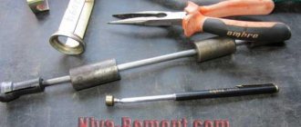
Tools:
Loosen the fastening clamp and disconnect the hose of the lower thermostat pipe. Loosen the fastening clamp and disconnect the hose of the thermostat side pipe. Loosen the fastening clamp and disconnect the fluid supply hose to the heater radiator from the cylinder head pipe. Unscrew the nuts of the fuel pipes and disconnect the fuel supply and drain lines.
Remove the upper bolt securing the rear intake pipe strut, loosen the lower bolt of the strut and move it to the side. Remove the two nuts securing the starter heat shield. Move the shield to the side.
Replacing the cylinder head gasket on cars
They are shown by arrows in Fig. To facilitate this work, you can use a lifting device by securing the head to the lifting eyes; — after removing the cylinder head, thoroughly clean the mating surfaces of the head and cylinder block.
If necessary, repair the cylinder head according to the instructions in subsection. They are located on the same side; — lubricate the threaded part and the contact areas of the cylinder head bolts with engine oil.
What is a cylinder head and its functions in a car engine
This is done after measuring the length of all bolts and replacing any overextended bolts. The cylinder head mounting bolts have different lengths and must therefore be installed in strict accordance with the markings and lengths.
There is no need to use a torque wrench to perform this job. Two M8 hex head bolts, shown at the bottom of Fig.
Once a certain mileage has been reached for the vehicle, subsequent tightening of the cylinder head fasteners is no longer necessary. A similar requirement existed previously for other types of cars; Note The cylinder head design can be modified.
For this reason, you should not purchase a used cylinder head until you are sure that it matches the one installed on your vehicle.
The location of the camshaft guide pin is at the top.
Location of the installation marks corresponding to the position of the piston of the first cylinder at TDC at the bottom: On the upper part of Fig. There is a mark on the camshaft that, when the piston of the first cylinder is at TDC, should be opposite the cast arrow on the bearing cap.
This location of the marks is shown at the bottom of Fig. Perform all other work in the reverse order of removal. Automotive products Advertising Website design and development After the expiration of copyright, in Russia this period is equal to three years, the work becomes public domain.