- engine starting system;
- battery charge elements;
- fuel mixture ignition system;
- elements of external and interior lighting;
- sensor system on the instrument panel;
- sound notification elements;
- fuse block.
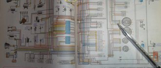
Electrical diagram of VAZ-2106 (old)
General diagram of the electrical equipment of VAZ 2106 / 21061 / 21063 / 21065 produced in 1976 - 1987.
1 – front lights; 2 – side direction indicators; 3 – battery; 4 – battery charge indicator relay; 5 – relay for turning on low beam headlights; 6 – relay for turning on the high beam headlights; 7 – starter; 8 – generator; 9 – external headlights; 10 – internal headlights; 11 – sound signals; 12 – electric motor of the engine cooling system fan; 13 – fan motor activation sensor; 14 – ignition coil; 15 – ignition distributor; 16 – spark plugs; 17 – carburetor solenoid valve; 18 – coolant temperature indicator sensor; 19 – engine compartment lamp; 20 – reverse light switch; 21 – oil pressure indicator sensor; 22 – sensor for low oil pressure indicator; 23 – indicator sensor for insufficient brake fluid level; 24 – windshield wiper gearmotor; 25 – windshield washer electric motor; 26 – relay for turning on sound signals; 27 – relay for turning on the fan motor; 28 – voltage regulator; 29 – windshield wiper relay; 30 – additional fuse block; 31 – main fuse block; 32 – relay-breaker for alarm and direction indicators; 33 – brake signal switch; 34 – plug socket for a portable lamp; 35 – heater electric motor; 36 – additional resistor of the heater electric motor; 37 – hours; 38 – heater motor switch; 39 – glove box lighting lamp; 40 – cigarette lighter; 41 – alarm switch; 42 – instrument lighting switch; 43 – warning lamp for insufficient brake fluid level; 44 – three-lever switch; 45 – ignition switch; 46 – rear fog lamp switch*; 47 – external lighting switch; 48 – lamp switches located in the front door pillars; 49 – switches for warning lights of open front doors; 50 – alarm lights for open front doors; 51 – lamp switches located in the rear door pillars; 52 – parking brake warning switch; 53 – interior lamps; 54 – fuel level indicator with reserve indicator; 55 – coolant temperature indicator; 56 – oil pressure gauge with low pressure indicator; 57 – tachometer; 58 – parking brake warning lamp; 59 – battery charge indicator lamp; 60 – carburetor air damper indicator lamp; 61 – side light indicator lamp; 62 – turn signal lamp; 63 – headlight high beam indicator lamp; 64 – speedometer; 65 – carburetor air damper warning switch; 66 – parking brake warning relay; 67 – rear lights; 68 – license plate lights; 69 – sensor for level indicator and fuel reserve; 70 – trunk lighting lamp; 71 – rear fog lamp*.
The order of conditional numbering of plugs in blocks:
a – windshield wiper and windshield wiper breaker relay; b – hazard warning and direction indicator breaker relay; c – three-lever switch.
Wiring diagram VAZ-2106 carburetor - full view:
Replacing the turn relay VAZ 2114
Now it’s time to talk about how to change the turn relay on a VAZ 2114. To carry out all the work you will need: - patience and free hands.
Replacement instructions:
- The first stage is the simplest - open the hood of the car.
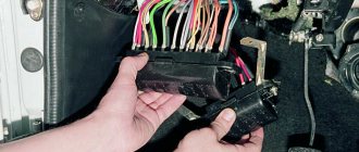
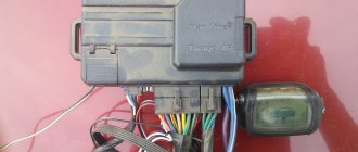
- At the second stage, you need to find the mounting block in which the desired product and fuses are located. Let us remember that the location of the MB is located directly above the right (driver's shock absorber strut).
- To access the contents of the block, we will need to open its plastic protective cover. This can be done by unlatching the two side latches.
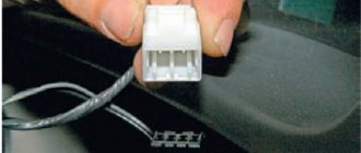
- Now you can observe the entire internal structure of the box, however, we are only interested in the product marked K2. Keep in mind that pulling the part out by hand is quite problematic and inconvenient. Especially for such purposes, you can find specialized plastic tweezers in the block, with the help of which it is very convenient to pull out the part and fuses, which we will certainly use.
- To reinstall, take a new product and insert it into the seat so that the three metal contacts are inserted into the socket. After this, press the body of the device and fix it firmly. This completes the replacement of the VAZ 2114 turn signal relay.
Electrical diagram of VAZ-2106 (new)
General diagram of the electrical equipment of VAZ 2106 / 21061 / 21063 / 21065, produced 1988 - 2001.
1 — front lights; 2 — side direction indicators; 3 - battery; 4 — battery charge indicator lamp relay; 5 – relay for turning on low beam headlights; 6 — relay for turning on the high beam headlights; 7 – starter; 8 – generator; 9 – external headlights; 10 – internal headlights; 11 – fan motor activation sensor; 12 — electric motor of the engine cooling system fan; 13 – sound signal; 14 – ignition coil; 15 – ignition distributor; 16 – spark plugs; 17 — carburetor solenoid valve; 18 – coolant temperature indicator sensor; 19 – engine compartment lamp; 20 – reverse light switch; 21 – oil pressure indicator sensor; 22 – low oil pressure indicator sensor; 23 – indicator sensor for insufficient brake fluid level; 24 — windshield wiper gearmotor; 25 – switch*; 26 — windshield washer electric motor; 27 – fan motor activation relay**; 28 – voltage regulator; 29 – windshield wiper relay; 30 – additional fuse block; 31 – main fuse block; 32 – relay-interrupter for alarm and direction indicators; 33 – relay for turning on the heated rear window***; 34 – brake light switch; 35 – plug socket for a portable lamp****; 36 – additional resistor of the heater electric motor; 37 – heater electric motor; 38 – heater motor switch; 39 – hours; 40 – glove box lighting lamp; 41 – cigarette lighter; 42 – alarm switch; 43 – instrument lighting regulator; 44 – brake fluid level indicator lamp; 45 – three-lever switch; 46 – ignition switch; 47 – rear window heating switch***; 48 – rear fog lamp switch; 49 – external lighting switch; 50 – lamp switches located in the front door pillars; 51 – gearmotors for electric windows of the front doors***; 52 – lamp switches located in the rear door pillars; 53 – parking brake warning lamp switch; 54 – interior lamps; 55 – fuel level indicator with reserve indicator; 56 – coolant temperature indicator; 57 – oil pressure indicator with low pressure indicator; 58 – tachometer; 59 – parking brake warning lamp; 60 – battery charge indicator lamp; 61 – carburetor air damper indicator lamp; 62 – side light indicator lamp; 63 – turn signal lamp; 64 – headlight high beam indicator lamp; 65 – speedometer VAZ-2106; 66 – carburetor air damper warning switch; 67 – power window switch for the left front door***; 68 – relay for turning on the electric windows of the front doors***; 69 – power window switch for the right front door***; 70 – rear lights; 71 – license plate lights; 72 – sensor for level indicator and fuel reserve; 73 – pads connected to the rear window heating element***; 74 – trunk lighting lamp; 75 – rear fog lamp.
The order of conditional numbering of plugs in blocks:
a – switch; b – ignition distributor sensor; c – windshield wiper and windshield wiper breaker relay; d – hazard warning and direction indicator breaker relay; d – three-lever switch.
* Installed if a vehicle uses a contactless ignition system. In this case, an ignition distributor sensor of type 38.3706 and an ignition coil of type 27.3705 or 027.3705 must be installed. ** Since 2000, it has not been installed and electric motor 12 is switched on directly by sensor-switch 11. In this case, instead of the previously used temperature sensor 11 of type TM-108, sensor-switch 661.3710 is used. *** Installed on car parts. **** Not installed since 2000.
Wiring diagram VAZ-2106 carburetor - full view:
Replacing the turn signal relay for a VAZ 2107
The design of the relay does not provide for the possibility of its repair. If a malfunction is detected, the part must be replaced.
If the relay is located in the mounting block, to replace it, simply follow these simple steps:
- open the cover of the mounting block;
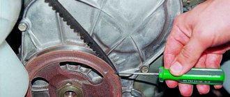
- pry with a screwdriver and remove the old relay;
- install a new relay;
- close the cover of the mounting block.
If the relay is located behind the dash, it is much more difficult to replace. To avoid a short circuit, it is better to disconnect the ground wire from the battery. Replacing the turn signal relay is done as follows:
- Unscrew and remove the button (handle) of the daily mileage counter.
- Remove the decorative handles from the interior heater control levers.
- Remove the decorative plug from the dashboard mounting screw.
- Unscrew the screw.
- Unclip the dashboard fasteners by prying it up with a screwdriver.
- Unclip the wire connectors from the instrument panel.
- Unscrew the speedometer cable by hand.
- Remove the dashboard.
- Unplug the wire terminals from the relay by turning.
- Unscrew the relay mounting nut.
- Connect wire terminals
- Reinstall the relay and tighten the mounting nut.
- Connect the wire terminals to the dashboard.
- Screw the speedometer cable to the dashboard.
- Place the panel in place by snapping the fasteners into place.
- Tighten the screw that secures the dashboard.
- Install decorative handles on the heater control levers.
- Screw on the trip odometer handle.
- Install the decorative plug onto the self-tapping screw.
After this, you need to connect the ground wire to the battery. Replacing the turn signal relay is now complete.
Turn signals are perhaps a very important part of any vehicle. Carrying out maneuvers on the road becomes a rather dangerous task if. The VAZ 2107 turn signal and hazard warning relay is responsible for the correct operation of the direction indicators. This device is used on all cars of the classic family. Let's consider why a turn signal relay is needed, how is a relay malfunction determined and how is it replaced?
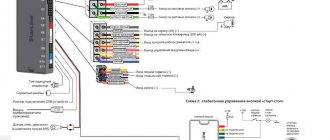
Wiring diagram VAZ 2106 (injector)
1 controller 2 electric fan of the cooling system 3 ignition system harness connector to the left mudguard harness 4 ignition system harness connector to the right mudguard harness 5 fuel level indicator 6 fuel level harness connector to the fuel level sensor harness 7 oxygen sensor 8 fuel level sensor harness connector to the system harness ignition 9 electric fuel pump 10 speed sensor 11 idle speed control 12 throttle position sensor 13 coolant temperature sensor 14 mass air flow sensor 15 diagnostic block 16 crankshaft position sensor 17 canister purge solenoid valve 18 ignition coil 19 spark plugs 20 VAZ-2106 injectors 21 ignition system harness block to instrument panel harness 22 electric fan relay 23 controller power supply circuit fuse 24 ignition relay 25 ignition relay fuse 26 electric fuel pump power circuit fuse 27 electric fuel pump relay 28 ignition system harness block to injector harness 29 injector harness block to ignition system harness 30 block g guta instrument panel to the ignition system harness 31 ignition switch 32 instrument cluster 33 engine anti-toxic system display
Useful: Pinout of diagnostic connector for VAZ cars
Injection engine control unit diagram
Electrical connection diagram for the injection engine control system:
1. — Controller connector. 2. — Mass air flow sensor. 3. — Coolant temperature sensor. 4. — Crankshaft position sensor. 5. — Throttle position sensor. 6. — Oxygen concentration sensor. 7. — Speed sensor. 8. — Ignition module. 9. — Electromagnetic valve for purge of the adsorber. 10. — Electric fan relay. 11. — Electric fuel pump relay. 12. — Main relay. 13. — Fuse protecting the power circuit of the electric fuel pump relay. 14. — Fuse protecting the power circuits of the main relay. 15. — Fuse link. 16 - Fuse protecting the constant power supply circuit of the controller. 17. — Diode. 18. — Idle speed regulator. 19. — Injectors. X1. — Diagnostic block. X2. — Connection block to the vehicle electrical system.
Schemes of individual six units
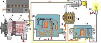
Generator connection diagram
1 — battery VAZ-2106; 2 — “six” generator set; 3 - regulatory device designed to control the operating voltage parameter; 4 - lock; 5 — plastic module with safety elements; 6 - control light indicator that determines the battery charge; 7 - relay that protects the power line of the battery charge indicator light.
Starter wiring diagram
1 — car starter device; 2 - battery; 3 - generator set; 4 - ignition switch.
Electrical circuits of the contact ignition system
1 — spark plugs; 2 - distributor; 3 — ignition switch; 4 - coil; 5 - switch; 6 - generator; 7 - battery.
Carburetor valve control circuit
1 - limit switching device of the carburetor unit; 2 - the engine valve itself; 3 - module used to control the carburetor unit; 4 — ignition coil; 5 - switching device; 6 - ignition switch, is a lock.
Wiring diagram of direction indicators and signaling
1 — lighting devices for turning lights installed in the front optical devices; 2 — battery VAZ-2106; 3 - car generator unit; 4 — side turning lights located on the front fenders; 5 — main mounting module with safety elements; 6 - auxiliary control unit with safety devices; 7 — ignition switch; 8 - device for turning off and activating the light signal, mounted in the car interior on the center console; 9 - switching device for activating and disabling turning lights; 10 - interrupting device used for blinking turning lights and light signals; 11 — speedometer, equipped with a control light indicator for activation of turning lights; 12 — light devices for direction indicators in the rear optics.
Electrical circuit for turning on the sound
1 - sound devices used to reproduce impulses; 2 - relay for activation of sound impulses, protects the electrical circuit from overvoltage; 3 — switch of sound pulses; 4 — mounting module with safety elements; 5 — generator set VAZ 2106; 6 - battery.
Switching diagram for electric windows
1 - main safety module; 2 - relay used to protect the power line of additionally installed power windows; 3 — switching device for the electric window mounted on the left door; 4 - a similar device used to adjust the position of the glass in the front right door; 5 — electric motor of the left glass lift; 6 — auxiliary module with safety elements; 7 - ignition switch.
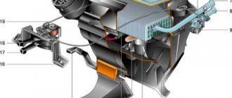
Engine cooling system diagram
1 — generator unit, installed under the hood; 2 - battery; 3 - ignition switch or lock; 4 — main module with safety elements; 5 - relay that protects the power line of the activation system of the electric motor of the power unit cooling fan; 6 — ventilation device activation controller; 7 - the fan itself; 8 - auxiliary safety module.
Malfunctions of turn signals VAZ 2107
The main symptom of a malfunction is non-functioning direction indicators. However, the reason may not be only the relay. There are several possible breakdowns:
- The turn signal lamps are constantly on and do not blink. This indicates a malfunction of the electromagnetic part of the VAZ 2107 turn signal relay - the contacts are stuck in the closed position and do not open. This could be either a burnt-out contact of the electromagnetic relay or a failure of the electronic circuit of the turn relay. Regardless of the specific reason, there is only one way out - replacing the VAZ 2107 turn signal relay.
- Lights flash too slowly or quickly. The reason may be either in the electronic part of the turn relay or in the discrepancy between the current consumption of the lamps and the nominal one. If one of the lamps has burned out or lamps that consume less current are installed, the turns will flash more often than necessary. The same phenomenon occurs if the wire going to one of the lamps is broken, or the lamp socket or base is oxidized. A similar phenomenon occurs when installing LED lamps instead of incandescent lamps. When installing more powerful lamps, the blinking frequency decreases. If all the lamps are in working order and the malfunction did not appear after replacing the lamps, the reason lies precisely in the turn relay or poor contacts in the lamp power circuit.
- The direction indicator lamps do not light up. The cause of the malfunction may be a broken turn switch, a burnt-out (faulty) turn relay, an open circuit, or a blown fuse. It is better to start checking from the last one
VAZ2107 fuse and relay diagram
The electrical wiring of the machine is protected by fuses, which are mainly installed in the central and additional units, located at the bottom of the instrument panel on the left side next to the steering column. The circuit from the battery to the terminals and connections is closed when the car ignition is turned on.
F1(16A) Klaxon, lamp socket, cigarette lighter, brake lamps, clock and interior lights (plafonds) F2(8A) Windshield wiper relay, heater and wiper motors, windshield washer F3(8A) Left headlight high beam and warning lamp on high beam F4(8A) High beam of the right headlight F5(8A) Low beam fuse of the left headlight F6(8A) Low beam of the right headlight and rear fog lamp F7(8A) This fuse in the VAZ 2106 block is responsible for the side light (left sidelight, right rear light), trunk light, license plate light right light bulb, instrument lighting lamps and cigarette lighter light F8(8A) Side light (right sidelight, left rear light), license plate light left light bulb, engine compartment lamp and side light warning light F9(8A) Oil pressure gauge with warning lamp, coolant temperature and fuel level indicator, battery charge warning lamp, direction indicators, carburetor choke indicator, rear window heating F10(8A) Voltage regulator and generator excitation winding F11(8A) Reserve F12(8 ) Reserve F13(8A) Reserve F14(16A) rear window heating F15(16A) Cooling system fan electric motor F16(8A) Turn indicators in hazard warning mode
Owners of 2106 should be aware that the old design of fuses has long become obsolete, since each time they operate they overheat, which affects the density of the cells. Lack of tight contact between the fuse and the connectors leads to their burning. Therefore, replacement of the fuse blocks is necessary. To avoid unnecessary problems with the electrical wiring, you should inspect the safety devices every six months. If the contact part burns, it is necessary to replace the fuses and clean the sockets. Today, many VAZ 2106 owners are modernizing classic blocks, replacing them with modern blade fuses.
Turn relay VAZ 2107
Unlike other lighting devices, the direction indicators operate intermittently and flash. A special device is responsible for the operation of the indicators - the VAZ 2107 turn signal relay. In addition to ensuring the blinking of the lamps, the relay performs a signaling function. It notifies you of the operation of the turn signals with audible signals - clicks.
At first, a thermal relay was installed on VAZ cars, in which the contacts were closed (opened) by a nichrome string, which heated and cooled due to the current passing through it. In later models, which include the “seven,” a relay with an electronic circuit and an electromagnet is used. The blinking frequency of the direction indicator lamps is determined by the settings of the electronic circuit. This design has fewer moving parts and contacts, and is therefore more reliable.
The device also performs the function of a VAZ 2107 emergency flasher relay, causing the lamps to flash when the hazard lights are turned on.
Modifications of the VAZ-2106 car
VAZ-21060 . Modification with the symbol VAZ-21060, Izhevsk assembly of recent years of production with a VAZ-21067 injection engine with a catalyst that meets the Euro-2 environmental standard
VAZ-21061 . Modification with a VAZ-2103 engine, some cars with a similar index were equipped with a simplified engine cooling system and did not have an electric fan. Instead, an impeller was installed on the end of the coolant pump shaft. Already Russian cars were equipped with bumpers from the VAZ-2105, some examples were equipped with cleaners and headlight washers.
VAZ-21062 . Export, right-handed modification of the base six.
VAZ-21063 . A car with an improved VAZ-21011 engine, with an oil pressure sensor and an electric engine cooling fan. The release of this modification was completed in 1994.
VAZ-21064 . Export, right-handed modification, like the VAZ-21062, but the VAZ-21061 modification was taken as the basis
VAZ-21065 . A modification of the car with improved equipment, which was produced from 1990 to 2001. An engine with a volume of 1569 cm3 was installed as a power unit. Other differences from the base model include a more powerful generator, a 5-speed gearbox, a rear axle gearbox with a gear ratio of 3.9, a contactless ignition system, and a Solex carburetor. There were other changes both in the exterior and in the interior, in general it was a “luxury” version of the VAZ-2106 sedan.
VAZ-21065-01. The same VAZ-21065 but with a VAZ-2103 engine
VAZ-21066 . Export, right-hand drive modification of the VAZ-21063 car.
VAZ-21068 . A car that was produced as a carrier of units during the development period of the new VAZ-2108 and VAZ-21083 engines.
VAZ-21069 . Modification of the VAZ-2106 manufactured by order of the special services. It was equipped with a two-section rotary piston engine VAZ-411 with a power of 120 hp, VAZ-413 with a power of 140 hp.
Diagnostics of malfunction of the direction indicator relay VAZ 2107
If one day the turn signals stopped working. It's time to check what happened and, if possible, replace the faulty part of the circuit. Malfunctions of the turn signal relay can be recognized by several signs:
- The turn signals light up but do not flicker
. This directly indicates a breakdown of the relay, or rather, its electromagnetic part. In this case, the electromagnet has closed in one of the positions and cannot return to its original state. - The turn signals blink too quickly or too slowly
. This can happen, but not only due to the fault of the turn signal relay. Sometimes the flickering speed of lamps can change if the turn signals use lamps that are not of the same power as those specified by the manufacturer. However, it wouldn't hurt to install a new relay as a test. - The turn signals don't work at all
. This means that the turn signal lamps and the lamp on the dashboard do not blink and there are no corresponding relay clicks. However, as in the second case, the malfunction does not always concern the turn signal relay. Sometimes the reason is a faulty hazard warning button.