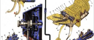
The design and principle of operation of the clutch
The pressure plate is located in a steel casing, which is bolted to the flywheel of the power plant. The friction disc is installed on the splines of the gearbox input shaft and is clamped by a diaphragm spring between the pressure disc and the flywheel. The guide bushing is a non-separable type unit, which includes the input shaft bearing and oil seal.
The bearing is moved by a ball bearing fork installed in the clutch housing. The fork is inserted into the grooves of the bearing coupling without fasteners. A drive (cable) is attached to the shoulder of this kind of shutdown lever, the second end of which is connected to the pedal in the cabin.
As the friction disc wears and operates, the clutch pedal travel is adjusted using an adjusting nut. It is located at the end of the cable.
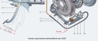
The hydraulic clutch drive of the Lada Largus with the JR5 gearbox consists of the following components:
- the master cylinder, which is installed in the engine compartment,
- slave cylinder in the clutch housing,
- release bearing,
- pipeline with tubes and hoses,
- pedal.
The pedal is connected to the master cylinder pushrod using a tip retainer. It is combined on one axis with the brake pedal and is attached to the body with a bracket. The pedal is equipped with a spring to allow it to return to its original position.
The master cylinder is connected to a reservoir that contains the brake fluid. The reservoir also serves to connect to the brake cylinder. The slave cylinder is combined with the clutch release bearing, attached to the crankcase from the inside and exerts pressure on the bearing through a diaphragm spring. The hydraulic drive operates thanks to the presence of brake fluid. It does not need adjustment during its entire service life.
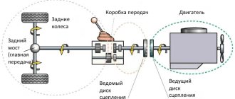
A flywheel is attached to the crankshaft of the Largus engine, which rotates during operation of the power unit. The flywheel contains a primary shaft, on the splines of which there is a clutch disc. Along these slots, the disc can move in both directions by several centimeters. The primary shaft is connected via a gear to the secondary shaft, which transmits torque to the axle shaft.
By pressing and releasing the clutch pedal, the driver adjusts the pressure of the disc from the engine flywheel. When the gear shift lever is moved to the neutral position, the secondary shaft gears do not mesh with the primary shaft gear. The same thing happens when the pedal is pressed: the driver engages the desired gear and, smoothly releasing the clutch, increases the speed. At this time, the gears gradually engage. The disc is pressed against the flywheel through the splines, thereby transmitting torque to the gearbox.
16-valve engines produce more power, so they use a clutch with a stiffer pressure spring and a friction disc damper. You can distinguish the discs by the slot of the spring petals and the damper springs, as they are marked with paint. The disk sizes used are the same.
You can install a disc from a 16-valve Largus engine onto an 8-valve one, but vice versa - you cannot.
Clutch drive - list and location of elements
LADA LARGUS cars can be equipped with a cable or hydraulic clutch drive, depending on the configuration. There is no gap between the clutch release bearing and the pressure spring petals. Cars equipped with the JH3 gearbox are equipped with a cable clutch, and the JR5 gearbox is equipped with a hydraulic clutch.
CABLE CLUTCH (for JH3 gearbox)
The clutch cable drive does not have an automatic clearance compensation mechanism. Single-disc, dry, with a central diaphragm spring. The mechanism is located in an aluminum crankcase, structurally integrated with the gearbox and attached to the engine cylinder block.
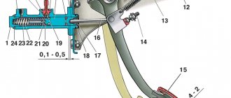
1 — clutch pedal; 2 — clutch cable; 3 — clutch release fork; 4 — clutch release bearing
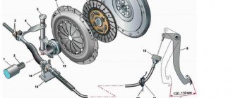
1 – clutch release bearing with clutch assembly; 2 – clutch release fork; 3 – pressure plate with casing assembly (“clutch basket”); 4 – driven disk
Clutch basket (pressure plate assembly): 1 – clutch cover; 2 – pressure disk; 3 – diaphragm spring; 4 – connecting plates
The clutch housing is connected by six bolts to the engine flywheel. Replacement of the “basket” is necessary when there is ring wear on the diaphragm spring blades to a depth of more than 0.8 mm, as well as in the case of a decrease in the effort on the pedal when disengaging the clutch (and, accordingly, an increase in the working stroke), which indicates large wear on the surface of the pressure plate or “ settlement" of the diaphragm spring.
Driven clutch disc: 1 – friction lining rivet; 2 – friction linings; 3 – spring plate; 4 – support finger; 5 – disk hub; 6 – damper spring; 7 – damper plate
The driven disk with a spring torsional vibration damper is installed on the splines of the gearbox input shaft between the flywheel and the pressure plate. Outer diameter 200 mm, thickness – 7.6 mm. The driven disk is replaced if its axial runout in the area of the friction linings is more than 0.5 mm, oiling, cracking, scuffing or uneven wear of the linings, loosening of the rivet joints, and also if the rivet heads are recessed from the surface of the linings by less than 0.2 mm.
Clutch cable: 1 – front cable tip; 2 – front end of the cable sheath; 3 – rear cable end; 4 – rear end of the cable sheath; 5 – cable; 6 – rubber support sleeve
The front end of the cable is fixed in the clutch release fork, and the rear end is in the clutch pedal holder. The front tip is threaded and is used to adjust the clutch release drive.
Clutch drive parts : 1 – clutch housing; 2 – clutch release bearing guide sleeve; 3 – clutch release bearing with clutch assembly; 4 – clutch release fork; 5 – dirt-proof cover
HYDRAULIC CLUTCH (for JR5 gearbox)
The clutch release drive is hydraulic. The force in it from the clutch pedal to the clutch release bearing is transmitted through the working fluid. The hydraulic drive consists of the clutch master and slave cylinders connected by a pipeline. The working fluid is poured into a reservoir, which is installed on the master cylinder and is used to power the brake system and the clutch release drive.
1 — clutch pedal; 2 — clutch master cylinder; 3 - pipeline connecting the main and slave cylinders of the clutch drive; 4 — clutch slave cylinder; 5 — supply pipeline of the clutch master cylinder; 6 — hydraulic brake reservoir
1 – clutch housing; 2 – clutch release bearing; 3 – clutch release working cylinder; 4 – pressure disk with casing assembly (“basket”); 5 – driven disk
“Basket” and driven disc of the clutch: 1 – casing; 2 – pressure disk; 3 – diaphragm spring; 4 – friction linings; 5 – damper springs; 6 – driven disk hub; 7 – damper
Elastic plates. The casing contains a diaphragm spring, which is stamped from sheet spring steel. When free, the spring has the shape of a truncated cone with radial slots extending from the inner edge of the spring. The spring slots form eighteen petals, which are elastic release levers. Due to the elasticity of the levers, the diaphragm spring creates more uniform pressure on the clutch pressure plate, which contributes to smoother engagement and disengagement of the clutch.
Arrangement of the wavy spring plate . The driven disk with a spring-loaded torsional vibration damper is mounted on the splines of the gearbox input shaft between the engine flywheel and the pressure plate. The torsional vibration damper dampens vibrations arising from dynamic loads in the transmission and uneven engine operation.
Idle damper . A disc hub is installed between the damper plates. Damper springs are installed in the grooves of the hub and damper plates. The damper plates are connected by support pins. In the disk hub, opposite the support posts, there are cutouts that allow the hub to rotate within certain limits relative to the damper plates, while compressing the damper springs. This allows you to reduce dynamic loads in the transmission when starting the car and changing gears.
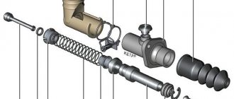
Clutch release bearing: 1 – bearing; 2 – working cylinder; 3 – fluid supply tube to the working cylinder
Parts of the working cylinder and clutch release bearing: 1 – clutch release bearing; 2 – protective cover; 3 – working cylinder; 4 – clamp; 5 – fluid supply tube to the working cylinder
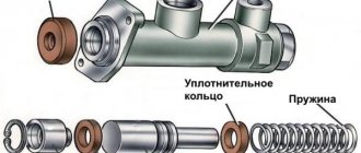
Clutch master cylinder: 1 – fitting for connecting the hydraulic drive tube; 2 – main cylinder body; 3 – fitting for connecting the liquid supply hose from the tank; 4 – pusher; 5 – pusher tip
Clutch hydraulic bleeder fitting: 1 – fluid supply tube to the working cylinder; 2 – bleeding fitting; 3 – clamp; 4 – clutch hydraulic tube
To pump the hydraulic clutch drive, there is a fitting on the plastic tube for supplying fluid to the working cylinder, closed with a rubber cap.
About car clutch
Note: This information is for general information purposes only.
Almost simultaneously with the internal combustion engine being installed under the hood of a car, a gearbox was needed for its efficient operation in various modes. When changing gears, it is necessary to smoothly disconnect the engine from the transmission; the clutch is designed for this purpose. It also protects power transmission parts from significant overloads.
At the dawn of motoring, while the search for optimal technical solutions was underway, a variety of clutch designs were used. The first machines were equipped with a belt clutch, in which a metal belt was in contact with a metal drum using various levers. Then came the cone clutch, a distant ancestor of today's dry single-plate clutches. Here, for the first time, the clutch was engaged using springs, and the flywheel was the leading element of the unit, its inner surface had a conical shape corresponding to the surface of the driven disk. Also, friction linings were used for the first time in such a scheme. However, for a number of reasons, this design is not widely used. Firstly, due to the complexity of the design, and secondly, due to the greater moment of inertia of the driven disk, which made it difficult to quickly change gears.
The cone clutch has been replaced by multi-disc designs. Moreover, both dry clutches and wet ones operating in an oil bath were used. Nowadays, such solutions are already implemented at a new technological level in robotic gearboxes. It is noteworthy that even then it became clear that the service life of wet clutches is several times higher and they are capable of transmitting more torque than dry clutches. Therefore, multi-plate wet clutches have been used for quite a long time on heavy trucks and military equipment. However, for mass-produced cars of those years, multi-disc designs were too complex. In addition, they had another drawback: at that time there were no synthetic oils, and mineral oils thickened when the temperature dropped, which led to an increase in effort when shifting gears.
As a result, the optimal solution was a single-plate dry clutch, consisting of a flywheel, casing, pressure plate, driven disk, release bearing, and bearing release clutch. The clutch in this design is engaged using springs; in the clutch of modern passenger cars, diaphragm springs are usually used.
A single-plate dry clutch, without significant changes in design, is still used on most modern cars, both cars and trucks. Such units are inexpensive to produce, repairable (replacing a clutch usually takes no more than two hours), and have high efficiency. The design is being improved mainly through the use of new, more wear-resistant materials, which has increased the service life (on some cars it is comparable to the service life of the car itself).
However, single-plate clutches also have quite a few disadvantages. Firstly, when changing gears, there is a break in the power flow, which is very bad when driving in difficult conditions, for example, off-road or when starting off on a steep hill. Secondly, as the driven disc wears, adjustment of the clutch drive is required. Thirdly, the clutch life greatly depends on various factors: operating conditions, load, driving style, etc. Fourthly, failure of each clutch part quickly leads to breakdown of the entire assembly, despite the fact that the design remains operational for some time. For example, wedging of the release bearing leads to rapid failure of both the driven and pressure disk, and in severe cases, damage to the expensive flywheel. Breakage of damper springs also leads to failure of the unit. Therefore, it is better to replace the entire assembly at the slightest sign of clutch malfunction, giving preference to products from well-known brands. Fifth, the torque that dry clutches can transmit is limited. Therefore, automakers often have to use different clutch models on the same model when using different types of engines. As a result, this leads to the fact that distributors and car service companies are forced to keep a large range of products in stock. Sixth, modern powerful turbo engines create significant torsional vibrations, which simple single-plate clutches are not able to completely absorb. Seventh, the very idea of using a manual transmission in combination with a single-plate dry clutch is far from the best; it has been proven that when operating in urban conditions, driver fatigue when driving a car with a manual transmission occurs 20-25% faster than in a car equipped with automatic transmission.
Designers are well aware of these problems and try to solve them whenever possible by offering new technical solutions. The resource of the unit was raised to an acceptable level thanks to the use of modern materials. Although outwardly all clutches look the same, their service life can differ tens of times. Only leading companies can afford to use expensive high-quality components in the manufacture of a unit. The problem with torsional vibrations was solved thanks to the invention of a design with a dual-mass flywheel. Here the torsional vibration damper is moved from the driven disk to the flywheel. This made it possible to reduce the load on both the clutch and gearbox parts. Today, this design is used by all leading car manufacturers with powerful engines.
As an inexpensive alternative to automatic transmissions, the robotic gearbox (also called automated) was invented back in the 1930s. Such designs, implemented at a new technical and technological level, began to be used en masse starting from the end of the last century, mainly on inexpensive cars. The main advantage of robotic gearboxes is their simplicity of design and low cost. This unit is based on a conventional manual gearbox. Economically, this is very beneficial for automakers - there is no need to master new technologies or spend additional funds on purchasing a transmission from a third-party manufacturer, as a result, the cost of a simple robotic gearbox is almost no different from a conventional mechanical one. However, the robotic box required several design changes. Electromagnetic devices called actuators are used to change gears and press the clutch. There was also another problem; During operation, the friction linings of the driven disk wear out and the pressure disk is gradually pressed against the flywheel. This leads to a change in the pressing force of the diaphragm spring blades. As you know, a “robot” can only work according to certain algorithms, so a wear compensator had to be introduced into the clutch design, allowing the characteristics of the unit to remain unchanged during its service life.
The main advantages of a robotic gearbox with one clutch are the low cost of both the unit itself and its repair (it is not much more complicated and expensive than a conventional manual gearbox). As a rule, only the clutch and actuators require replacement during operation. Also, such gearboxes are light and compact.
However, there are also many disadvantages. The most important thing is that, just like with a classic “mechanics”, when changing gears there is a break in the power flow. The second is the torque limit. The third is the limited service life of clutches; in urban operating conditions they require replacement every 50-70 thousand kilometers. Fourth, the “robot” works according to certain algorithms, which are not always optimal for specific conditions. For the design to work adequately, you have to spend a lot of time and money developing these algorithms. As a result, today single-clutch robotic transmissions have limited use, mainly used by automakers who do not have the funds to develop or purchase more advanced gearboxes.
Today, the most advanced transmission option based on manual gearboxes is a robotic transmission with two clutches. It works as follows. The gearbox has two coaxial shafts. One is responsible for turning on odd gears, the second - even ones. This transmission has two clutch packs, which are controlled automatically using an electronic control unit (mechatronics). This design allows you to keep two gears engaged at the same time, and depending on driving conditions, the electronics selects one of the two, high or low. Everything worked reliably as long as such transmissions had wet clutches. But wet clutches have lower efficiency, and now manufacturers, to please the demands of environmentalists, are fighting for every extra gram of fuel consumed, so when the robotic gearbox was brought to perfection, they tried to remove the oil circuit and make such a transmission with two dry clutches. The Volkswagen Group was the first to use this design on a large scale; this gearbox was called the DSG200. However, it soon became clear that in a metropolis, the service life of clutches does not exceed several tens of thousands of kilometers. Over the course of several years, the design was refined, the settings of the control electronics were repeatedly changed, as a result, now there are no problems with this unit, the clutches last at least 100 thousand km. However, the upgraded DSG200 gearbox is only installed on cars with engines with a displacement of no more than 13 liters. But similar-design robotic gearboxes with wet clutches turned out to be more promising. The 6-speed DSG250, although predating the DSG200, is still widely used. The pinnacle of development today is the DSG500 robot with wet clutches, which is capable of transmitting high torque and today is compatible with most Volkswagen Group vehicles with powerful engines, including diesel ones.
Nowadays, robotic gearboxes with two clutches are used by many leading automakers, for example Ford, Hyundai, FCA. In terms of their consumer qualities, they are not inferior to automatic transmissions with a torque converter, and in some ways they are superior to them. The main advantage of such transmissions is fast gear shifting: in just 8 ms, which provides good dynamics and reduces fuel consumption. Compared to a manual transmission, a dual-clutch robotic transmission can reduce fuel consumption by up to 6% and by 15-20% compared to automatic transmissions with torque converters. With such transmissions there is practically no interruption in the power flow. Structurally, a “robot” with two clutches is two mechanical gearboxes assembled. This is a plus for automakers - there is no need to create a separate mechanical production. But on the other hand, such gearboxes have more weight compared to a conventional manual gearbox. Such transmissions are complex in design and maintenance. Repairs require an expensive set of original clutches. As previously mentioned, in such a gearbox, when the car is moving, two gears are always engaged at the same time, even and odd, even at a standstill, if the transmission control selector is moved to the “neutral” position, first gear and reverse are engaged at the same time. In this design, accelerated wear of the synchronizers and gear fork bearings occurs. On the other hand, manufacturers of auto components know about this and have mastered the production of relatively inexpensive repair kits. Therefore, robotic transmissions are more repairable than most modern automatic transmissions and CVTs. The mechanical part of the “robots” is reliable and does not cause problems during operation. As a result, repairing robotic transmissions usually costs less than automatic transmissions. It is difficult to say whether robotic gearboxes with two clutches will receive further development. On the one hand, the Volkswagen Group has almost completely abandoned the use of automatic transmissions with torque converters in favor of “robots”. On the other hand, modern “automatic machines” have become more advanced; thanks to locking the torque converter when driving in top gear, they have managed to increase efficiency, so some automakers who installed “robots” in their cars are now switching to automatic transmissions. (material used by S. Dyakonov and Autocomponents magazine)
Basic malfunctions and methods for their elimination
The most obvious reason for the failure of the Lada Largus clutch is oil contamination. If this happens, the clutch cannot be replaced until the leak is fixed. There can be two sources of leakage: engine or gearbox. Oil can leak out of the engine due to a worn oil seal behind the flywheel. Changing it is quite difficult due to the labor-intensive dismantling process.
If lubricant gets in from the gearbox, the culprit is a worn oil seal located on the front of the gearbox. To replace the unit, you will need to drain the oil from the gearbox and separate the final drive housing from the gearbox housing. The process is labor-intensive, but necessary. To remove the oil seal, you will also need to remove the flywheel.
Before proceeding with the removal and disassembly of the clutch, it is necessary to check the reliability of the fixing elements that attract the assembly to the Largus frame and engine. If the fasteners are loose or the rubber bushings are worn out, when pressing the pedal the driver will feel shaking and jerking when moving away.
Bleeding the clutch of Lada Largus
Bleeding is only relevant for the hydraulic drive on the JR5 gearbox. This must be done if air has entered the hydraulic system and an air lock has formed. Signs of a problem: the clutch begins to “drive”, and when the pedal is fully pressed, the friction clutch does not disengage completely. When you engage any gear, a characteristic grinding sound of gears is heard, and the lever becomes difficult to control.
To bleed the clutch, you must first replace the brake fluid and restore the sealing of the brake and clutch systems. Without this, the pedal will simply fail. To work, you will need a flat-head screwdriver, new brake fluid, a suitable container and a hose that matches the diameter of the fitting. The pumping process is as follows:
- Check the brake fluid level in the reservoir and top up to the maximum level if necessary.
- Remove the protective cap from the clutch slave cylinder fitting and put on a suitable hose (for example, from a dropper). The second end must be lowered into a container to drain the brake fluid.
- Next you will need an assistant. Its task is to press the clutch pedal at least 10 times at intervals of several seconds.
- Use an 8 mm wrench to loosen the fitting, use a screwdriver to pry up the spring clamp and lift it until it clicks. The tip from the cylinder pipe is displaced by 1 cm.
- The assistant depresses the clutch and holds the pedal, at which time the liquid from the cylinder flows through the hose into the container.
- After the liquid stops flowing, the fitting is tightened, the tip of the cylinder pipe is pushed back and secured with a spring retainer.
- After this, the pedal can be released and the operation repeated after 5-10 seconds.
Hydraulic Clutch Actuator - Bleeding
general description
Possible faults
If the following malfunctions occur, it is necessary to check the hydraulic clutch drive system for fluid leaks and remove air from the system:
— the appearance of free play of the clutch pedal;
— the clutch pedal is in the middle or depressed position;
- Difficulty shifting gears.
Possible consequences of contamination entering the hydraulic clutch system
The hydraulic clutch drive is very sensitive to contamination. The entry of contaminants into the system can lead to the following consequences:
— inability to change gears;
— damage or complete failure of the hydraulic clutch;
— leaks from the hydraulic clutch drive.
To remove air from the hydraulic clutch drive, use the following equipment:
— installation for removing air from the hydraulic drive system through a brake fluid reservoir type OMA 883 f. "OMA" (Italy);
— a syringe for removing air through a fitting located on the clutch slave cylinder.
Hydraulic Clutch Bleeding Procedures
If parts of the hydraulic clutch are removed
Perform bleed operations using a bleeder through the brake fluid reservoir or a new syringe through the bleeder located on the clutch slave cylinder (brake fluid).
If the clutch hydraulic parts are not removed
Perform air bleeding operations with a syringe only by injecting brake fluid through the air bleeding fitting on the clutch slave cylinder.
Place the vehicle on a two-post lift, apply the parking brake and turn off the ignition.
Remove the engine crankcase protection (see here)
Bleeding procedure if there are no removed hydraulic drive parts
Bleeding using a unit to remove air from the hydraulic drive system
Secure the clutch pedal in the up position using a strap attached to the steering wheel to ensure hydraulic integrity during the bleeding operation.
Connect the installation for removing air from the hydraulic drive system to the brake fluid reservoir (installation for removing air from the hydraulic drive system type OMA 883 f. "OMA", Italy).
Remove plug 1, Figure 8-1, from the air bleeder fitting on clutch slave cylinder 4.
Connect the transparent tube to the air removal fitting, lowering the other end into an empty vessel located above the air removal fitting (transparent process tube, process vessel).
Press the lock 2 and pull out the pipeline 3 one click to open the air bleed hole.
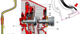
Figure 8-1 — Removing air from the hydraulic clutch system:
1 — plug of the fitting for removing air; 2 — clamp; 3 - pipeline connecting the main and slave cylinders of the clutch drive; 4 — clutch slave cylinder; 5 - gearbox
Open the system between the bleeder unit and the brake fluid reservoir.
Wait until the brake fluid flows out without bubbles.
Relieve pressure in the clutch hydraulic drive by turning off the air bleeder.
Press the lock and install the pipeline into the working cylinder until it clicks.
Disconnect the transparent tube from the air bleed fitting and install the plug on the fitting.
Disconnect the bleeder unit.
Add brake fluid to the master cylinder reservoir and bring the level to normal. The brake fluid level should be between the “MAX” and “MIN” marks on the master cylinder reservoir.
Press the clutch pedal twenty times quickly.
Check the functionality of the clutch. If necessary, repeat the air removal operation.
Pumping with a syringe
Secure the clutch pedal in the up position using a strap attached to the steering wheel to ensure hydraulic integrity during the bleeding operation.
Remove the plug from fitting 1, Figure 8-1, to remove air from clutch slave cylinder 4.
Attach a transparent tube to the air removal fitting so that it takes the same height position as the tank (technological tube).
Press the lock 2 and pull out the pipeline 3 one click to open the air bleed hole.
Pour brake fluid into the master cylinder reservoir until it flows out of the clutch hydraulic bleeder nipple.
Attach a new syringe for bleeding the hydraulic clutch drive system to the end of the transparent tube, filled with 60 ml of brake fluid (technological syringe).
Slowly and completely displace the brake fluid from the syringe into the hydraulic clutch actuator, making sure that no air from the top of the syringe enters the system.
Press the lock and install the pipeline into the working cylinder until it clicks.
Disconnect the transparent tube from the bleeder fitting.
Place a plug on the fitting to remove air.
Bring the brake fluid level in the master cylinder reservoir to normal. The brake fluid level should be between the “MAX” and “MIN” marks on the master cylinder reservoir.
Press the clutch pedal twenty times quickly.
Check the functionality of the clutch. If necessary, repeat the air removal operation.
Bleeding preparation procedure if hydraulic clutch actuator parts are removed
Pipeline preparation
Fill the hydraulic clutch line, Figure 8-2, using a syringe.
Figure 8-2 — Clutch hydraulic line
Connect the filled line to the clutch slave cylinder to prevent brake fluid leakage.
Preparing the hydraulic clutch slave cylinder
Fill the hydraulic clutch slave cylinder, Figure 8-3, using a syringe under its own weight.
Figure 8-3 — Hydraulic clutch slave cylinder
Install the appropriate part (or parts) on the vehicle
Bleeding procedure after removing part of the hydraulic system
Secure the clutch pedal in the up position using a strap attached to the steering wheel to ensure hydraulic integrity during the bleeding operation.
Remove the plug from fitting 1, Figure 8-1, to remove air from clutch slave cylinder 4.
Attach a transparent tube to the air removal fitting so that it takes the same height position as the tank (technological tube).
Press the lock 2 and pull out the pipeline 3 one click to open the air bleed hole.
Pour brake fluid into the master cylinder reservoir until it flows out of the clutch bleeder nipple.
Connect a new syringe to the end of the transparent tube, filled with 60 ml of brake fluid.
Slowly and completely displace the fluid from the syringe into the clutch hydraulic actuator, making sure that no air from the top of the syringe enters the system.
Press the lock and install the pipeline into the working cylinder until it clicks.
Disconnect the transparent tube from the bleeder fitting.
Install a plug on the air bleeder fitting. Bring the brake fluid level to normal. The brake fluid level should be between the “MAX” and “MIN” marks on the master cylinder reservoir.
Press the clutch pedal twenty times quickly.
Check the functionality of the clutch.
If necessary, repeat the air removal operation.
Install engine crankcase protection
Video
Replacing the friction clutch
Repairing the Larugsa clutch, like any other car, does not make sense; all worn parts must be replaced. To work, you will need a standard set of tools, amplifiers, a hammer and a new set of spare parts. First, the car must be placed on a lift or its front part raised on jacks above the inspection hole. The front wheels and engine protection are removed. After unscrewing the screws, you need to remove the left shield under the bumper. This will give you access to the shield fasteners in the wheel arch, which must also be removed.
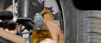
The gearbox oil is drained into a suitable container; to do this, first unscrew the plastic and then the metal plug. Do not remove the reservoir until maximum oil has been drained. Dismantle the brake caliper and put it aside along with the pads.
Removing the steering knuckle
Removal is carried out according to the following scheme:
- disconnect the ABS sensor;
- Using a 16 mm wrench, unscrew the nut on the tie rod screw, use a screwdriver to open the two sides of the knuckle, and press out the ball joint rod;
- on the steering end stud, unscrew the nut with a 16 mm wrench and press out the stud;
- Using two 18 mm wrenches, unscrew the fastening nuts that secure the fist to the stand. Now you can remove the steering knuckle, and also dismantle the CV joint from the gearbox (in this case, the rollers will probably fall out).
It is impossible to replace the clutch on a Largus without draining the oil, since the internal drive mechanisms (CV joints) cannot be unscrewed if there is lubricant in the gearbox.
Working in the engine compartment
First you need to disconnect the negative terminal of the battery and remove the cable. To do this, the counterweight is pulled forward, removed through the slot, after which the rubber coupling is removed through it. The engine harness holder is attached to the gearbox housing. To remove it, just loosen the fastener. Now you need to disconnect all the wire terminals:
- unscrew the two mounting screws and remove the terminal from the TDC sensor;
- Disable the reverse sensor at the gearbox;
- disconnect the speed sensor terminal;
- The oxygen concentration sensor (lambda probe) is also disconnected.
The breather hose needs to be loosened and moved away from the box, unscrew the two wires to ground. Next, find the gearshift knob rod, loosen the fastening and pull out the rod.
A mark is left on the fastening clamp using paint so that the rod can be placed correctly during installation.
Removing the gearbox
It is impossible to replace the clutch on a Lada Largus without removing the gearbox. First you need to remove the subframe by unscrewing the three bolts securing it to the bumper. Then the rear support bracket is removed, the steering mounting bolts and the power steering mounting bolt on the left on the subframe are unscrewed. The exhaust pipe is disconnected from the exhaust manifold and removed from the rubber hangers. The subframe is attached to the body with 4 bolts - they need to be unscrewed. Additionally, you will have to remove the starter.
It remains to remove the two screws on top - they secure the gearbox to the engine - and the four bolts with which the clutch housing is attached to the oil sump. Suitable supports are first installed under the engine and gearbox. At the very end, the left engine mount bracket is dismantled, after which the nuts on the lower studs are unscrewed.
Replacing the mechanism
To remove the basket, perform the following operations:
- using an 11 mm wrench, unscrew 6 bolts that hold the basket, fixing it on the flywheel - one turn at a time, sequentially;
- holding the friction disc, remove the basket.
After replacing all worn elements, the assembly is assembled, and the steps are performed in the reverse order. For installation you will need to use heat-resistant grease and a centering mandrel.
Clutch adjustment
Ideally centering and balancing the friction clutch by doing the assembly yourself will be problematic, but possible. To adjust the tension with your own hands, you need to perform a number of actions:
- find the nuts for adjusting the clutch pedal (located under the power steering reservoir);
- unscrew the outer nut to the end of the stud;
- using the second nut, the travel of the clutch pedal is adjusted to the desired cable tension;
- After this, the external nut secures the fastener so that in the future it does not loosen and the cable does not fly off.
If the Largus clutch is adjusted correctly, first gear will engage easily. When the engine is running and the clutch pedal is fully depressed, there should be no crunching, crackling, spontaneous increase or decrease in speed.