Cars admin26.02.2020
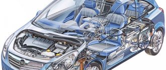
A car has two power sources - a battery and a generator. The battery is used to start the engine and to supply 12 V electric current to the starter and other consumers when the engine is not running. When the engine is running, the main source of current - the generator - provides electric current to all consumers, including the ignition system, and charges the battery.
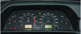
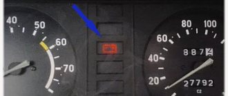
If the red battery charging lamp is on on the dashboard, it means that current is not flowing from the generator to the on-board network and the battery’s energy reserves are being consumed. This supply is limited and depends on capacity. If the battery is fully charged, you can drive to the garage without a generator, but it is better to try to fix the problem on the spot.
| EXECUTION ORDER |
1.
Check if the alternator drive belt is broken.
If the belt is intact, check its tension. Press the top of the belt with your thumb and see how much it bends. Normal tension is ensured when the belt deflects 10–15 mm.
Is the belt tension normal?
2.
Using a “17” wrench, loosen the nut securing the generator to the adjusting bracket, insert a mounting blade between the generator and the engine cylinder block and use this “lever” to move the generator away from the engine. Tighten the generator mounting nut.
3.
Check whether the corresponding fuse has blown.
The location of the fuses and their ratings are indicated in this manual ( see the section “Electrical faults” ), in the vehicle repair manual, in a separate electrical diagram, on the cover of the mounting block and on the fuses themselves.
4.
Replace the fuse.
Do not install fuses designed for a higher rated current: this can lead to damage to electrical equipment and even a fire.
Start the engine and check if the battery charging lamp goes out.
Has the charging light gone out?
5.
Bon Voyage!
6.
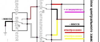
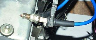
Check the wire going from the generator to the positive terminal of the battery. Two wires are connected to it: the thicker one connects the battery to the starter, the thin one connects to the generator. The wire may be broken, broken inside the insulation, or have oxidized or unreliable contacts. Correct the problem and start the engine.
No: see point 8
7.
Bon Voyage!
8.
If, after taking the measures, the charging lamp continues to light up while the engine is running, then the possible cause of the malfunction lies in the generator itself. There may be several reasons, and to eliminate them it is better to use the help of a specialist, and you just have to hope that the energy reserve in the battery is enough to get to the car service center.
To reduce current consumption when driving a car with a faulty alternator, if possible, turn off the radio, unnecessary lights, heater fan, defroster, etc.
A) Belt break.
Carefully examine the presence of a belt on the water pump and generator pulleys. To return it to its destination, you will need socket wrenches 17 or 13, depending on the year of manufacture of the car, as well as a strong flat-head screwdriver.
Disconnect the HF position sensor (for example, at 21213,21214).
Loosen the nuts securing the tension bar and slide it to the side towards the cylinder block.
Put a belt on your professionalism landing place.
After installation is complete, adjust the tension, controlling the deflection when pressing with a huge finger on the clearance of the belt between the generator and pump pulleys - 10-15 mm, pump and crankshaft - 12-17 mm. Failure to comply with this requirement may result in the belt slipping with subsequent damage and rupture.
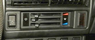
Main and additional fuse blocks
These two blocks are connected to each other. There are 10 fuses in the upper block, and 6 in the lower one. Markings from left to right:
| F1 (16A) | Heater fan, rear window defroster, rear wiper and washer system, windshield washer pump |
| F2 (8A) | Steering column switch, windshield wipers, hazard warning lights, breaker relay (in turn signal mode), reverse light, instrument cluster (coolant temperature gauge, fuel level gauge, tachometer, warning lights: turn indicators, differential lock, parking brake, emergency condition of the working brake system, insufficient oil pressure, fuel reserve, battery charge) |
| F3 (8A) | Left headlight (high beam), high beam indicator lamp |
| F4 (8A) | Right headlight (high beam) |
| F5 (8A) | Left headlight (low beam) |
| F6 (8A) | Right headlight (low beam) |
| F7 (8A) | Side light lamps in the left front and left rear lights, license plate lights, side light indicator lamp |
| F8 (8A) | Side light lamps in the right front and right rear lamps, backlight lamps for the instrument cluster, cigarette lighter, switches, heating and ventilation control unit |
| F9 (8A) | Hazard switch, breaker relay (in hazard mode), heated tailgate glass relay contacts |
| F10 (8A) | Sound signal, interior lamps, brake lamps in the rear lights |
| F11, F12 (8A) | Reserve |
| F13 (8A) | Fog light relay contacts in rear lights |
| F14 (16A) | Cigarette lighter |
| F15 (16A), F16 (8A) | Reserve |
Additional block:
| F11 (8A) | Turn signal lamps and relay-breaker for turn signals and hazard warning lights (in hazard warning mode) |
| F12 (8A) | Daytime running light relay, daytime running light bulbs |
| F13 (8A) | Rear Fog Lamps and Relays |
| F14 (16A) | Cigarette lighter |
| F15 (16A) | Spare |
| F16 (8A) | Spare |
Additional fuse circuits in the Urban package:
| Fuse number and rating | Protected circuit |
| Main unit | |
| 1 (16A)* | Electric windows for front doors Electric side mirrors |
| 2 (16A)** | Air conditioning fan, air conditioning compressor |
| 9 (16A)* | Side mirror heaters |
| 10 (16A)* | Central interior lamp |
| Additional block | |
| 15 (16A)* | Air conditioning fan, air conditioning compressor |
Battery charging lamp VAZ 21214
After replacing the alternator belt, charging
, as a result, the battery died and the controller stopped working.
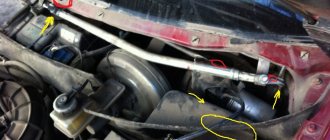
The location where the charging relay is located near the Niva is determined by the age of the car. Thus, a remote relay
can be found on the right fender liner of a car with a classic engine compartment layout; more modern modifications of generators are equipped with a LV combined with a brush assembly.
The element is not repaired, but replaced completely. To assess the condition, you will need power supplies of 12-14 V, followed by replacement with 16-22 V, and also an incandescent lamp of 1-3 W. According to the diagram drawing, apply current to the voltage regulator in series. If the first test is characterized by the operation of the lamp, and the second - by the absence of glow, then the LV is working.
If there is a break, the lamp will not light up at all; if there is a breakdown, it will glow constantly. In addition, weak charging, as well as its absolute absence, is often explained by abrasion of the brushes (residual height less than 5 mm) and slip rings of the generator. If the first part is changed along with the brush holder, then the second is restored by grinding, grooving or removing the remains of the old rings and pressing in new ones. It is recommended to supplement the disassembly of the unit with a total cleaning.
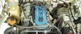
Location of fuse and relay blocks Lada 4×4
The main part of the fuses is located in the interior of the Lada 4×4 under the panel to the left of the steering column. Total 4 blocks:
1 — engine control system fuse box; 2 — windshield wiper relay; 3 — fuse blocks; 4 — relay block of the engine control system.
The fourth relay block is located above the gas pedal.
The charging lamp does not light up.
Since the indicator on the instrument panel
is a link in the excitation circuit of the generator; the absence of flashing when the ignition is turned on leads to loss of its functionality.
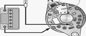
Whether the lamp is to blame or the reason lies elsewhere (voltage regulator relay, lock contact group), can be understood by disconnecting terminal 61 from the generator with the ignition on, followed by shorting the wire from the instrument panel to the car body. If it catches fire, check the serviceability of the rotor winding, brushes and “chocolate”. If the circumstances are otherwise, examine the performance of fuse No. 2 (8A) and the light bulb by replacing the ones mentioned with known good ones.
Engine Control Relay Box
It is located under the main fuse box and consists of 5 relays and 1 fuse.
Scheme
Electrical diagram of the block
Decoding
- Ignition relay
- Main relay
- Right cooling fan relay
- Left cooling fan relay
- Fuel pump relay
- Fuel pump fuse F5 15A
The only difference between Nivas with injection and carburetor systems is due to the fact that the engine control relay unit can be located under the hood of the car in a specially designated compartment.
The signal lamp is blinking
Blinking of the battery indicator, as a rule, indicates problems in the brush assembly, as well as the occurrence of a short circuit in the “W” and “-” terminals of the voltage regulator. The brushes, in turn, can “freeze”, not reaching slip rings at low and medium speeds. You have already read how to fix them in our instructions. However, the reason why charging on the Niva 2121, 2131, 21214 and 4×4 Urban disappeared is not always the above-mentioned components under the hood. In particular, the culprit of weak charging or its complete absence is an unmaintained battery with an insufficient volume of electrolyte or closed banks, loose and oxidized terminals, broken and melted wires. Additional difficulties arise when dirt, dust, traces of fuel and lubricants, etc. accumulate on suspended equipment.
Problems with the generator
The most common malfunction of this unit is brush wear. At the initial stage, it manifests itself as periodic power surges. Symptom: the charging control lamp on the instrument panel blinks periodically - the battery charging indicator lamp, because charging is either there or not.
On a note! Often, brush failure occurs on the fly without any blinking. Yesterday everything worked, today the generator is not breathing.
On a VAZ 2121, the brush block is attached to the generator with one screw and connected to the relay-regulator using knife terminals, the condition of which is also very advisable to check.
In all other Niva car models, the brushes are made in one unit with a relay regulator. Car enthusiasts who consider themselves cool “brewed” call this block “chocolate”.
Remove the back cover of the generator. We disconnect the wires from the brushes (VAZ 2121) and “chocolate” (other models), take out the block and assess the condition of the brushes. They should not be burnt, crumbled at the edges or protrude from the body by less than 5 mm. If something is not right, we change it.
The next problem is wear on the slip rings of the generator rotor. Quite “adult” cars suffer from this disease. Remove the back cover from the generator and carefully inspect the rings.
If they are in bad condition, we replace them. You can see how to replace the slip ring block in the video below.
Replacing the Niva generator rotor slip ring block
The next malfunction is the failure of rectifier or additional diodes. In order to check them, you will have to disconnect all stator windings. They are connected to the diodes using screw lugs.
We unscrew, remove, and test each diode with a multimeter set to diode testing mode. In direct connection, the device should show several hundred Ohms, in reverse - an infinitely large resistance. If this is not the case, change the diodes. Since the semiconductors are pressed into metal plates in the form of a double horseshoe, which are radiators and conductors, you will have to change the entire group of diodes along with the “horseshoe”. Additional diodes can be changed one at a time using a soldering iron.
Expert opinion
Alexey Bartosh
Specialist in repair and maintenance of electrical equipment and industrial electronics.
Ask a Question
To check the diodes, it is enough to disconnect the windings; there is no need to unsolder additional diodes. They will not interfere with the continuity of the rectifier diodes and will themselves ring perfectly.
Well, the last malfunction is a break or breakdown of the stator or rotor windings. We remove the brushes, turn off the windings and check them with an ohmmeter for breaks and short circuits to the housing. In addition to a break and a short to the housing, an interturn short circuit is possible. Without special equipment, it is impossible to detect a short-circuited turn, so you will have to limit yourself to only estimating the resistance and the lack of connection with the generator housing.
In the video below you can see how the field winding is checked using an audio test.
Continuity of the generator excitation winding
Lada 4×4 3D Nivasos › Logbook › We defeat the generator. Relay regulator 845.3702 for VAZ 21214
I stopped by, asked for a RR from Shniva, and at the same time took a new diode bridge to “set it and forget it.” Well, the price tags are certainly high here, but I don’t want to wait and there won’t be time to deal with this issue later.
In the end I took the gentleman's set:
With one movement of the hand we remove the generator