Dashboard diagram of VAZ 2114 injector
The instrument cluster on the VAZ 2114 is located on the left side of the dashboard, which motorists often call a “torpedo”. The dashboard also contains various switches and indicator lights that are necessary to control lighting equipment, heater and other important units.
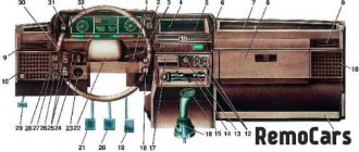
Instrument panel VAZ 2114
Designation of icons on the instrument panel of the VAZ 2114: indicators, buttons and lights
Published by: admin in Tips for car enthusiasts 04/29/2018 0 494 Views
The instrument cluster on the VAZ 2114 is located on the left side of the dashboard, which motorists often call a “torpedo”. The dashboard also contains various switches and indicator lights that are necessary to control lighting equipment, heater and other important units.
Instrument panel VAZ 2114
Purpose of VAZ 2114 devices and interpretation of the symbols on them
Located on the left side of the dashboard, directly in front of the driver's seat, the VAZ 2114 instrument cluster plays an important role in driving. It contains pointer instruments, VAZ 2114 indicators with electronic digital windows and signal lights for various purposes.
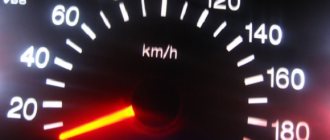
- An induction speedometer, which receives speed readings from a sensor located directly in the gearbox, shows the actual speed of the car from zero to two hundred kilometers per hour. The division price is 10 km/h. It must be borne in mind that such devices have a permissible error of at least 5 km/h. In the lower, central part of the device there is a window with an electronic display, in which two lines reflect the total mileage for the entire period of operation of the car and the current mileage.
- To the left of the speedometer is the tachometer. This is an electronic device that, receiving a signal from the on-board computer, shows the current crankshaft speed at that particular moment. The scale has divisions of 5 units, digitization is done after 10 units, the maximum value is 80. When multiplied by 100, the real number of revolutions is obtained, for example, 30 multiplied by 100, the result is 3000 rpm. The range of 55 - 60 is shaded in red - this signals that the critical speed is approaching. The critical range 60 - 80 is shaded in red. If the speed increases to these values, the engine may fail. In the lower middle part of the device, an electronic display displays the time and real ambient temperature.
- To the left of the tachometer there is a dial gauge for the coolant temperature. It receives a signal about the actual condition from the coolant temperature sensor, which is located between the cylinder head and the thermostat. The division value is 20 degrees. Digitization of the device begins at 50, after two divisions it is 90 and the divisions end at 130 degrees. The red, danger zone starts at 105 degrees. If the arrow falls into this zone, then the engine must be turned off immediately, no matter what mode it is operating in. Due to overheating of the engine, failure of the main blocks of the power unit is possible. At the top, near the number 130, there is a graphic temperature icon. To the right of the speedometer is a device indicating the presence and level of fuel in the car’s fuel tank.
The numbers on the scale indicate:
- 0 is an empty tank.
- ½ - half a tank.
- 1 is a full tank.
The graphic symbol of a gas station at the top of the device indicates a fully filled tank. At the bottom right, an indicator in the form of a gas pump lights up in orange, indicating that the remainder in the tank is less than six liters.
Basic devices and their interpretation
Of course, the most significant instruments on the dashboard are:
- Speedometer;
- Tachometer;
- Coolant temperature indicator;
- Fuel level indicator in the tank.
Instrument cluster
Let's study them in more detail.
- Speedometer. The VAZ 2114 provides for the installation of an induction speedometer, which receives speed data thanks to a sensor located on the gearbox. The speedometer shows the current speed of the vehicle. The scale is divided from 0 to 200 kilometers per hour in increments of 10 kilometers per hour. Such devices have an error of at least 5 kilometers per hour. At the bottom center of the speedometer is a two-line display. She reports the current mileage, and the second one reports the total mileage completed on this car.
- Tachometer. It is located to the left of the speedometer. The tachometer is an electronic device that receives signals from the on-board computer and reflects the current crankshaft speed. The scale is divided into 5 units. Digitization - every 10 scale units. The maximum tachometer scale is 80. Multiplying this number by 100, we get the number of revolutions. For example, if the scale is 40, then the crankshaft rotates 4000 rpm. The range from 55 to 60 has red shading, and 80 is completely red. These are critical speeds, when the arrow reaches which the engine operates under extreme loads and may fail. At the bottom of the tachometer in the middle the time and air temperature are displayed.
- Coolant temperature indicator. The coolant temperature should be constantly monitored, because for this purpose there is a corresponding indicator on the dashboard. It is located to the left of the tachometer and reports the current coolant temperature. The data comes from the corresponding sensor. The division is made in 20 degree increments. Digitization starts at 50, then goes to 90 and 130. The danger zone begins at 105 degrees. If the arrow is in this zone, the engine must be stopped immediately, otherwise overheating and breakdown will occur.
- Fuel level indicator. It is located to the right of the speedometer. The scale shows numbers and images that mean: 0 - the tank is empty;
- 1/2 - the tank is half full;
- tank full;
- Image of a gas station at the top - the tank is filled to its maximum capacity;
- Image of a gas station at the bottom right with orange backlight - less than 6 liters of fuel left in the tank.
Designation of light bulbs and indicators on the instrument panel of the VAZ 2114
The dashboard, by definition, is designed to contain instruments, indicators and switches that could inform the driver about the current state of various vehicle systems, signal an emergency during the operation of the car or the failure of any units, as well as using buttons and switches control individual equipment or mechanisms.
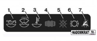
The designation of icons on the instrument panel of the VAZ 2114 is made in accordance with all requirements and standards that call for the unification of symbols so that they are absolutely clear to every driver. The symbols on the instrument panel of a VAZ 2114 with the latest injection engine are located mainly in the lower part of the instrument cluster:
Indicators VAZ 2114
1 - the icon of the light indicating that the oil level in the engine crankcase has dropped below the minimum level, lights up in red;
2 - this light indicates an insufficient level of washer fluid; it lights up orange when the remainder in the tank is less than one liter;
3 - this icon, lighting up in orange, indicates a decrease in the coolant level in the expansion tank with a cold engine below the permissible level;
4 — warning light icon for unlocked doors, lights up red;
5 — fault indicator for “brake lights” or dimensions;
6 - this is a warning light for a malfunction in the brake system, indicating that the brake pads are worn out;
7 - light bulb icon that indicates unfastened seat belts.
On earlier versions of the car, the designation of the light bulbs on the dashboard of the VAZ 2114 in the lower part is slightly different, when viewed from left to right:
Designation of icons on the instrument panel of the VAZ 2114
- emergency oil pressure icon (18), lights up red when the level drops below the minimum;
- red handbrake indicator light (17), if it is on, it means the brake is not released;
- a warning light with an icon representing a battery (16), which lights up when it is discharged;
- warning light (9), indicating that the brake fluid level in the reservoir has dropped below the minimum level.
In addition, car enthusiasts should know what the lights on the VAZ 2114 instrument panel mean, indicating the performance of the lighting equipment or the condition of the engine:
- in the upper part of the instrument cluster between the speedometer and tachometer there are two green arrows (3 and 4) indicating that the turn signals are on on the left or right;
- Below is a triangular red emergency stop icon (13);
- under the emergency stop sign there is a CHECK ENGINE light (14), which lights up red when any malfunction occurs in the engine automation;
- on the right there is a blue light bulb for high beam (10), which lights up when it is turned on, and a green light bulb (8) for low beam.
Designation of icons on the instrument panel of the VAZ 2114
What do the indicators on the VAZ 2114 dashboard mean? Please describe.
The instrument panel on the “fourteenth” is quite compact, with a minimum of indicators. It’s easy to understand each of them, but for beginners we recommend studying each of the available symbols. The picture and the following list will help with this:
- Coolant temperature scale . A temperature range from 50 to 120 degrees is presented. The arrow moving into the red sector indicates overheating of the motor. Further diagnosis and determination of the cause is required.
- Tachometer . Shows at what speed the crankshaft rotates. The red zone informs about exceeding the norm. It is not recommended to increase the speed to these values.
- A flashing green arrow indicator indicates that the left turn signal is on.
- A flashing green arrow indicator indicates that the right turn signal is on.
- Speedometer . Shows the vehicle speed in kilometers per hour (scale up to 200 km/h).
- Fuel tank full indicator.
- The “refueling” indicator indicates a low amount of fuel . Lights up when approximately 6-7 liters remain in the tank.
- The “light bulb” indicator indicates that the dimensions are turned on . Lights up only when the outside light is on.
- Red exclamation mark indicator . Indicates the unsatisfactory condition of the braking system, in particular when the brake fluid level is low. It is not allowed to operate the car with the indicator on.
- The headlight indicator indicates that the high beam .
- Button for resetting the mileage to zero and setting the clock.
- Kilometer counter . The top number is the total mileage of the vehicle, and the bottom number is the mileage per day.
- And the “red triangle” tram indicates that the emergency signal is on.
- CHECK ENGINE icon . When the car is in good condition, it lights up once when the ignition is turned on and goes out immediately. Flashes or lights up if one of the sensors in the motor has detected a malfunction or incorrect data.
- Time and temperature indicator.
- The “battery” icon indicates a low battery charge . In normal mode, it lights up once and goes out after ignition. If it is constantly on, diagnostics and testing of the generator or other system components is necessary.
- The “P in a circle” indicator shows the status of the handbrake. Lights up when the lever is raised up.
- The oil can indicator lights up when the oil pressure in the system is critically low.
- Choke position (on a car with a carburetor).
These are all the designations in the standard Lada 2114 panel.
Identification of buttons
It is also important to know the designation of the buttons on the VAZ 2114 panel. On the instrument cluster on the right side there is a button (11), with which the time and temperature on the digital indicator are switched, and when pressed for 5 seconds or more, the current mileage is reset, if pressed this button on a stationary car.
In the central part of the dashboard are located in a row:
Buttons VAZ 2114
Double headlight switch. Button 1 turns on the dimensions, button 2 turns on the low beam;
Buttons on VAZ 2114
Key switch block. The first 1 turns on the front fog lights, the second 2 turns on the rear fog lights and the third 3 turns on the heated rear window.
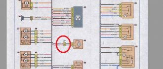
Wiring diagram for VAZ 2114 injector 8 valves with a detailed description of the electrical system, engine compartment wiring, fuses, harnesses and high-voltage wires. Wiring diagrams for VAZ 2114 injector 8 valves are presented in high-resolution color format for more detailed viewing.
Wiring diagram VAZ 2114 injector 8 valves
- Rear window heating switch;
- Rear fog lamp switch;
- Switch for headlights and direction indicators;
- Mounting block;
- Wiper switch;
- Fog light switch;
- On-board control system display unit;
- Instrument panel harness block to additional harness;
- Instrument cluster;
- Instrument panel harness connector to on-board computer harness;
- Instrument panel harness connector to ignition system harness;
- Instrument panel harness to side door harness;
- Fuse 16 A;
- Fuse 16 A;
- Ignition switch;
- Light switch;
- Heater motor;
- Additional resistance of the heater electric motor;
- Ignition switch relief relay;
- Rear fog light relay;
- Starter relay;
- Cartridge for connecting a portable lamp;
- Cigarette lighter;
- Instrument panel harness connector to glove compartment lamp wiring harness;
- Illuminator;
- Illuminator;
- Illuminator;
- Heater switch;
- Instrument lighting regulator with rheostat;
- Brake light switch;
- Horn switch;
- Hazard switch;
- Heater control panel backlight;
- Fuse 16 A;
- Seat heating relay;
Dashboard buttons
The dashboard of a car contains several buttons. Next to the clock and thermometer there is a button that allows you to switch these indicators and reset the current mileage. The following buttons are located in the center of the instrument panel:
- parking lights;
- low beam
- front fog lights;
- rear PTF;
- heated rear window.
Also, many car owners move the hazard warning button here. The backlight of the button allows you to clearly see it in the dark.
Underhood wiring diagram VAZ 2114 injector
Diagram of the underhood wiring of a VAZ 2114 injector and front harness connections with a detailed description of the electrical equipment, connection diagram, indicating the mounting block and connected devices.
- Starter;
- Rechargeable battery;
- Generator;
- Battery and starter harness pads and front harness;
- Mounting block;
- Sound signal;
- Coolant temperature indicator sensor;
- Washer fluid level sensor;
- Left headlight;
- Headlight right;
- Ambient temperature sensor;
- Reversing light switch;
- Engine electric fan;
- Front harness block to ignition system harness;
- The block is used on cars with a carburetor;
- Brake fluid level sensor;
- Oil level sensor;
- Coolant level sensor;
- Mounting block;
- Oil pressure warning light sensor;
- Rear window washer motor;
- Washer motor;
- Wiper motor;
Ш5-Ш8, Ш11 - mounting block connectors. A1, A2, B1, B2 - grounding points of the front harness.
VDO
The instrument cluster from VDO is more modern. It has stylish LED backlighting, as well as some differences in connecting certain connectors from the previous version. Such devices were installed both at the factory on the latest cars of this model, and are often installed independently by car owners. For example, some drivers install a panel from Lada Kalina.
The pinout of the VAZ 2114 instrument panel in this case looks like this:
- pink and white input – to the electric power steering (if installed independently);
- blue and white - to the emergency warning light;
- gray-blue – leads to the oil pressure sensor;
- brown-blue - to the handbrake switch;
- blue with yellow - leads to the immobilizer control unit (not used on 2114);
- black – to the block that controls the airbag (not applicable on the “fourteenth”);
- yellow – to the lighting switch (external);
- blue – leads to the right direction indicator;
- black and blue - to the left turn signal;
- white-blue – to the electronic control unit;
- to a sensor showing the degree of wear of the brake pads (this VAZ is not installed on this model);
- to the seat belt sensor;
- black - leads to the block that controls the traction control system (not installed on the 4);
- red-blue – “RESET” key on the steering column switch;
- blue with pink - to the brake fluid level sensor;
- black – to ABS (VAZ 2114 does not have it);
- green – leads to the high beam switch;
- white – goes to the instrument panel lighting control;
- brown – tidy weight;
- white-red – terminal 30;
- orange – terminal 15;
- red-yellow - to the sensor indicating fuel consumption;
- orange-white – MK “Forward” key;
- white-black – MK “Back” key;
- black and white – outside temperature sensor (-);
- yellow-green – outside temperature sensor (+);
- pink - to the fuel level sensor;
- gray – leads to the speed sensor;
- green-white – to the coolant level sensor;
- brown-red – to the tachometer (low voltage);
- service (for panel diagnostics);
- terminal L of the relay-regulator on the generator.
Since such a tidy is also used on the Lada Kalina, equipped with more modern equipment, some inputs when installed on 2114 will remain free, since this car does not have such equipment (unless, of course, it was additionally installed by the owner himself).
Wiring diagram VAZ 2114 injector - rear harness
Wiring diagram for VAZ 2114 fwafva injector
- Mounting block;
- Rear window heating element;
- Rear window wiper motor;
- License plate light;
- License plate light;
- Left side turn signal;
- Side turn signal right;
- Individual lighting lamp;
- Interior lamp;
- Handbrake sensor;
- Left lamp;
- Right lamp;
- Additional brake signal;
- Interior lamp switch;
- Interior lamp switch;
- Interior lamp switch;
- Interior lamp switch;
Ready-made dashboards
FLASH X3
Flash X3 has a large number of backlight shades, and a smarter screen of the control and diagnostic device is installed in the center, where operating parameters, diagnostics, and service support of the vehicle are indicated.
The positions of the instruments also differ from the standard ones and are made in a more harmonious style, which emphasizes the rigor of the model’s design. There is a function for digital display of engine speed and vehicle speed.
Useful : VAZ 2114 dashboard pinout
The dashboard has functions for diagnosing the vehicle's condition through the ECU. The price for Flash X3 in online stores is about 9,000 rubles .
FLASH X103M
Another device from this brand, but with a better design. The driver is left with a minimum of mechanical indicators: tachometer, speedometer. The rest is all displayed on the big screen between them.
The Flash X103M model is distinguished by its information content. There is no need to use special diagnostic equipment to find out the reasons for improper engine operation or increased fuel consumption. Everything is within easy reach of the driver. The number of backlight shades has been increased, and control is made using only three steering column keys. This helped make screen operation intuitive and comfortable. The price for such a panel is about 13,000 rubles .
GAMMA 826 GF
Another interesting option, which in its execution looks better than many modern foreign car models. Gamma 826 GF is made in pleasant colors and has the ability to display current engine characteristics. Additionally, it is equipped with chambers from the same brand, information from which is displayed on the display.
It is also controlled by a steering column switch, but according to the description it does not boast diagnostic capabilities, unlike its competitors. But it clearly wins with its design using OPTITRON technology and high contrast devices, which emphasizes its rigor. It has the ability to alert with an audible signal in various situations: an increase in coolant temperature, driving without turning on the low beam, exceeding the speed threshold, exceeding the engine speed threshold, insufficient oil pressure, etc. The price of the model on the market is about 33,000 rubles .
Do-it-yourself car panel tuning is considered an easy way to transform the interior, and the expense will not hit your pocket. By replacing standard bulbs with LED bulbs, you not only improve the appearance of your dashboard, but also increase the visibility of the dials on it. But if you want to get additional functions and are willing to pay for it, you should definitely order a ready-made tuning instrument panel for the VAZ 2114, which, in addition to its design, will surprise you with its functionality.
Wiring diagram VAZ 2114 injector - side door harness
Wiring diagram for side doors of VAZ 2114 with a detailed description of electrical connections, harnesses and electric locks.
- Side door wiring harness connector to instrument panel harness;
- Side door wiring harness connector to seat heating harness;
- Electric lock of the right rear door;
- Electric lock of the left rear door;
- Harness block to rear right loudspeaker;
- Harness block to rear left loudspeaker;
- Door lock control unit;
- Side door wiring harness connectors to the additional left harness;
- Side door wiring harness connectors to the additional left harness;
- Terminals of the side door wiring harness to the radio;
- Side door wiring harness block to the additional right harness;
A1 is the grounding point for the side door wiring harness.
Instrument panel lighting for VAZ 2114, 2115. Diagnostics, repair.
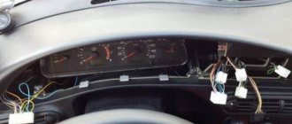
The instrument panel is a rather complex unit, and accordingly it can fail, like any other part of the car. The panel often does not work or stops lighting.
What are the main problems that can be observed with a faulty dashboard of the VAZ 2114, 2115:
1. The main illumination of the PP has disappeared, but the remaining sensors continue to work or vice versa. Most often, this problem occurs when the panel fuses fail. They are marked F16. In addition to illuminating the panel, such a fuse is also responsible for the turn signals, as well as the hazard warning lights, and the reversing lights. If the hazard lights and turn signals work normally, then most likely the problem is in the electrical circuit, or a short circuit may have occurred.
The video below shows how to fix the dashboard backlight:
2. The speedometer and tachometer are not working properly. In this case, it is first recommended to check the crankshaft position sensors, as well as speed sensors. If these sensors work correctly, then the problem may be poor electrical contact or damage to the wiring itself.
3. If some sensors do not work, but other elements work correctly, then the light bulbs may have failed. In this case, you just need to replace them with new ones.
4. If the arrow indicating the fuel level in the tank or the coolant level has dropped to the very bottom, or vice versa is always in the upper position, then most likely the problem is in the sensors or electrical circuit. There is no need to rush to replace sensors. First check the wiring to see if it is working properly and if there is any short circuit. In this case, it is best to turn to professionals.
5. It often happens that in general the dashboard works normally, but from time to time there are interruptions in the operation of some sensors. Often the cause is in the electrical circuit. The reason may also be due to incorrect operation of the processor.
Wiring diagram VAZ 2114 injector - mounting block
Wiring diagram of the mounting block VAZ 2114 injector 8 valves with a full description
K1 - relay for turning on headlight cleaners; K2 - relay-interrupter for direction indicators and hazard warning lights; K3 - windshield wiper relay; K4 - lamp health monitoring relay; K5 - power window relay; K6 - relay for turning on sound signals; K7 — relay for turning on the electric heating of the rear window; K8 - headlight high beam relay; K9 - relay for low beam headlights; F1-F20 - fuses; X11 - terminals of the wiring harness block. The power supply circuit of the injection systems is protected by a fuse-link made of wire with a cross-section of 1 mm. Powerful consumers (starter, headlights) are connected to the VAZ 2114 injector wiring diagram via a relay.
F1 (10A) - Headlight cleaners. Relay for turning on headlight cleaners (contacts). Valve for turning on headlight washers.
F2 (10A) - Direction indicators and hazard warning relay-breaker. Hazard warning lamp.
F3 (10A) - Rear lights (brake lamps). Interior lighting.
F4 (20A) - Rear window heating element. Relay for turning on the heated rear window. Socket for portable lamp.е
F5 (20A) - Electric motor of the engine cooling system fan and switching relay (contacts). Sound signal and relay for its activation.
F6 (30A) - Power windows for front doors. Relay for turning on electric lifts.
F7 (30A) - Headlight cleaners (in operating mode). Relay for turning on headlight cleaners (winding). Heater fan motor. Window washer motor. Rear window wiper motor. Rear window washer timing relay.
F8 (7.5A) - Left fog lamp.
F9 (7.5A) - Right fog lamp.
F10 (7.5A) - Left headlight (side light). Left rear light (side light). License plate lights. Engine compartment lamp. Instrument lighting lamps. Indicator lamp for external lighting. Heater lever illumination display.
F11 (7.5A) - Right headlight (side light). Right rear light.
F12 (7.5A) - Right headlight (low beam).
F13 (7.5A) - Left headlight (low beam).
F14 (7.5A) - Left headlight (high beam). Indicator lamp for turning on the high beam headlights.
F15 (7.5A) - Right headlight (high beam).
F16 (15A) - Direction indicators and relay-breaker for direction indicators and hazard warning lights (in turn indication mode). Turn signal indicator lamp. Rear lights (reversing lamp). Gearmotor and windshield wiper activation relay. Generator excitation winding (when starting the engine). Oil pressure warning lamp. Air damper control. Coolant temperature gauge.
The VAZ dashboard has an electronic combination, as well as conveniently located backlighting. The lamps are illuminated from the inside, which is a feature of the 14th Lada.
Thanks to the instrument panel, the driver knows all the information he needs, what is the reserve and consumption of gasoline, mileage, etc. The panel should be easy to operate with a clear overview of the icons, scale, gauge and indicators.
What is the state of the automobile systems responsible for road safety, driving speed, the rest of the way to the intended object, rational engine operation and gasoline consumption, the operation of the suspension and electrical equipment - all this should be reflected on the control panel.
Signal lamps and equipment control devices must be required on the panel. There are a total of 19 symbols on the panel.
Schetmash
The “Schetmash” instrument panel was set to “fourteenth” from the first days of production. Subsequently, VDO devices began to be installed on the car. But even among the cars of recent years, there are sometimes cars with this panel.
For this device, the pinout of the VAZ 2114 instrument panel is as follows:
For white block (X1):
- 1 black – weight per body;
- 2 purple - brown - to the tachometer (input from the ECU, low voltage);
- 3 yellow – tachometer (input from the ignition module, high-voltage);
- 4 purple - white - fuse F3;
- 5 white-green – antifreeze level sensor;
- 6 brown – fuse F10;
- 7 reserve;
- 8 purple - white - Check Engine;
- 9 pink - black - to the electronic control unit;
- 10 orange – sensor indicating the gasoline level;
- 11 brown-blue - to the hand brake;
- 12 white-brown - to output D on the generator;
- 13 blue-blue – engine oil level sensor.
For the red chip (X2):
- 1 purple-blue - to the outside air temperature sensor;
- 2 orange - fuse F16;
- 3 black - weight per body;
- 4 white — dashboard lighting;
- 5 blue - to the right direction indicator;
- 6 black and blue - to the left turn indicator;
- 7 pink-blue - brake fluid level sensor;
- 8 brown - leads to the on-board computer;
- 9 yellow-gray - sensor indicating speed;
- 10 pink - fuel level sensor;
- 11 black-green - fuse F14;
- 12 – to the alarm;
- 13 purple - terminal 50 on the ignition switch.
As can be seen from the description, the location of certain connectors on the instrument panels is slightly different. When replacing the device with a more modern one, or vice versa, the motorist may experience some connection difficulties. Therefore, if you have no experience in auto electrics, it is better to entrust such tuning to specialists.
Control panel design
The main symbols include the fuel level, speedometer, tachometer, and sensors for cooling the liquid. The temperature sensor is indicated by an arrow on the left side of the panel.
If the sensor needle is in the zone from 105 to 130 degrees, you should immediately stop the car and wait until the engine cools down, otherwise the engine will simply boil. The tachometer is presented in the form of a dial scale on the instrument panel.
Engine speeds from 2 to 5.5 thousand per minute are considered the norm. If the needle falls into the red zone, fuel consumption may increase sharply, and the load on engine parts will become greater. The panel must have a speedometer.
With its help, the driver controls the speed, which directly affects road safety. The speedometer is an important part and should show clear data.
The sensor is located in the form of an arrow, which shows the fuel level in the car tank and is usually located on the right side of the device. Although it will not measure exact data about gasoline, you can find out the approximate fuel remaining at any time.
The panel design is quite simple, and at the same time highly informative; removing it is not difficult.
With the help of sensors and meters, the driver is aware of all the information about his car. The VAZ tidy is made of plastic, which gives it an aesthetic appearance; it does not creak at all, unlike the same nine.
The device is simple, easy to disassemble and assemble.
Pinout, tuning, lighting and removal of the VAZ-2114 instrument panel
The VAZ dashboard has an electronic combination, as well as conveniently located backlighting. The lamps are illuminated from the inside, which is a feature of the 14th Lada.
Thanks to the instrument panel, the driver knows all the information he needs, what is the reserve and consumption of gasoline, mileage, etc. The panel should be easy to operate with a clear overview of the icons, scale, gauge and indicators.
What is the state of the automobile systems responsible for road safety, driving speed, the rest of the way to the intended object, rational engine operation and gasoline consumption, the operation of the suspension and electrical equipment - all this should be reflected on the control panel.
Signal lamps and equipment control devices must be required on the panel. There are a total of 19 symbols on the panel.
VAZ 2114 instrument panel pinout
Electrical connection diagram for the instrument panel of the VAZ 2114 (Click on the picture to enlarge)
- — rear window heating switch;
- — rear fog lamp switch;
- — switch for headlights and direction indicators;
- — mounting block;
- — windshield wiper switch;
- — fog light switch;
- — display unit of the on-board control system;
- — block of the instrument panel harness to the additional harness;
- — instrument cluster;
- — instrument panel harness connector to the on-board computer harness;
- — block of the instrument panel harness to the ignition system harness;
- — block of the instrument panel harness to the side door harness;
- — fuse 16 A;
- — fuse 16 A;
- — ignition switch;
- — lighting switch;
- — heater electric motor;
- — additional resistance of the heater electric motor;
- — ignition switch unloading relay;
- — Rear fog lights relay;
- - starter relay;
- — socket for connecting a portable lamp;
- - cigarette lighter;
- — block of the instrument panel harness to the wiring harness of the glove box lighting lamp;
- — illuminator;
- — illuminator;
- — illuminator;
- — heater switch;
- — instrument lighting regulator with rheostat;
- — brake signal switch;
- - horn switch;
- - hazard warning switch;
- — backlight lamp for heater control panel;
- — fuse 16 A;
- — seat heating relay;
The panel pinout is a diagram, but the diagram described in words seems easier for many. The contacts located on the instrument panel, and there are only 26 of them, are responsible for the operation of the indicators on the panel itself.
If a plus is applied, then each of the contacts shows information and the state in which the car is currently located. The panel is equipped with sensors and signal indicators, and the panel is controlled using an electronic unit.
Inside the panel there are two pads - red and white. Fuses, inputs and outputs, controllers are connected to a specific plug. If the sensors fail, they need to be replaced.
You can check the serviceability of the wiring by disassembling the instrument panel. Oxidized or damaged wires must be replaced. Indicator lights may fail. Burnt out light bulbs must be replaced with new ones.
A faulty lamp sensor must also be replaced. The contact between the board and the lamp must be well connected, otherwise the ends of the contacts should be cleaned, bent, and if necessary, replace the lamp socket.
If the backlight stops working or the radio is faulty, the fuse must be replaced. Maybe the damage is not in the fuse, but in the wiring, which also requires replacement.
A short circuit in the fuse can also damage it.
Description of the buttons on the instrument panel of the VAZ 2114
When purchasing a new or used car, the first thing the owner must do is figure out exactly how to operate the car and all its systems. To do this, you should know the pinout of the instrument panel on the VAZ 2114, since this is the car we are talking about today.
Dashboard
We bring to your attention a detailed description of the buttons on the VAZ 2114 dashboard, icons, lights and other devices and indicators.
Tuning the dashboard of Lada 2114
To make their car distinctive, many motorists resort to tuning.
Although this is a troublesome task, it is worth it. Everyone strives to make the salon spectacular and cozy. The dashboard is a favorite place for tuning.
Backlight tuning
To make the panel devices look stylish and modern, they can be modernized. Let's look at how backlight tuning is done.
You can improve the appearance of a vehicle yourself, since the process is not at all complicated.
Everything you need for tuning:
- panel disassembly;
- removing the shield;
- tune the necessary parts;
- put in place.
The first step is to replace regular yellow light bulbs with bright LEDs. Chinese diodes are cheaper, but they will not last long. To ensure that the light comes directly from the diodes, heat shrink is put on them, and the arrows will be clearly visible even in the dark.
The diode wires are connected to the backlight from the machine stove. To change the color of the arrows, a red diode is placed under each arrow. The light from the arrows will acquire a rich, bright red color, which will noticeably update the panel.
Blue light bulbs are popular. The central panel is also subject to tuning, respect is guaranteed. The glow becomes soft and irritates the eyes when driving.
Europanel
To give a modern aesthetic look, you can install a europanel.
The material of the panel is soft, rich, and less noisy. The original warning lamps and odometer make the panel modern and fashionable. It is equipped with many signal sensors. A special feature of the Europanel are sensor signals and airbags. White-blue LEDs also look beautiful. Typically, up to 50 LEDs are needed for tuning. If the glow of the diodes is very bright, then you can try to adjust it. Some VAZ components have this capability.
You can also tint the instrument panel, which will also look great. Improving the panel offers ample opportunities for creativity among car enthusiasts and designers. As a tuning option, you can install a start button, which will give the interior a distinctive style and modernity.
By the way, if the modernization will be carried out with your own hands, in order to avoid problems with the traffic police, you need to write a statement about the planned changes in the design of the car and wait for permission from the traffic police. After making changes, you need to undergo a technical inspection, where appropriate changes will be made to the registration documents.
Designations of light bulbs, indicators, icons and buttons on the instrument panel of VAZ 2114, 2115
First, let's look at the descriptions and meaning of the panel icons and buttons, regardless of whether the car is equipped with an injector or a carburetor.
1 - Control sensor that measures the temperature of the coolant in the engine cooling system. During normal operation of the power unit, the antifreeze temperature should not exceed 90 degrees. But minimal deviations are sometimes acceptable. If you notice that the engine begins to overheat frequently, be sure to contact a car service center for help. Sometimes the sensor itself may give incorrect results.
2 - A device such as a tachometer processes information that comes from the crankshaft and displays it on the panel. The tachometer readings indicate the number of engine revolutions.
3.4 - Turn indicators. If the indicators flash simultaneously, but slowly, this may indicate a possible problem with the bulbs themselves or in the electrical wiring network.
5 — The most basic element of any instrument panel is the speedometer. Thanks to it, the driver can determine the speed of movement. A slight error in the indicators is allowed, but it should not exceed the indicator by more than 5 kilometers. If such readings differ significantly from the real ones, then most likely the problem is in the speedometer.
6 — Fuel level sensor in the fuel tank. When the level in the tank drops to 6-7 liters, a red light comes on, indicating that the car needs to be refueled.
7 - Low fuel level indicator.
8 — Symbol indicating the light is turned on. It is triggered when the low beam and parking lights are turned on.
9 — The brake light indicates that the vehicle’s brake system is not working correctly. Most often it lights up if there is not enough brake fluid in the car.
10 - A blue light indicates that the high beam headlights are on.
11 — Button for resetting the daily mileage. The total mileage of the car is shown at the top, and the daily mileage at the bottom.
12 - on-board computer display with mileage indicators.
13 — Alarm activation symbol (light). When the emergency light is turned on, the light begins to flash red.
14 — “Check” symbol. It is triggered in case of possible problems with the car’s power unit. There can be many reasons for this, from problems with mixing the combustible mixture with air, to breakdowns of various engine power components. In any case, you need to contact the service for computer diagnostics or repairs.
15 — External air temperature sensor and time indicators. The daily mileage reset button allows you to scroll from the temperature readings to the time readings when scrolling.
16 - Battery charge sensor. Most often it lights up when the battery is almost completely discharged. If the indicator light is very weak or, on the contrary, bright, then the problem may be in the generator.
17 - Handbrake activation icon. It lights up both when the engine is on and vice versa.
18 — Icon showing engine fluid pressure. Usually its appearance indicates an insufficient amount of lubricating mixture. In such a case, be sure to check the oil level. Sometimes the problem can be caused by the oil pump not working properly.
19 - If the engine is equipped with an injector, then there is a reserve icon on the dashboard. Well, if the engine is carburetor, then this is a suction indicator.
- Dimensions switch
- dipped headlights
- Front fog light button
- Rear fog lights
- Heated rear window
Instrument panel lighting
The role of illumination on the panel is performed by incandescent lamps located at the top of the panel. Even higher, there is a green filter. The standard backlight color can be changed to a beautiful LED color.
To do this, you will need three LEDs, cartridges for them, foil and tape. The green filter can be removed altogether, or replaced with a different color.
And if you put a white LED on top of the filter, the glow will become brighter and more beautiful. The service life of the battery will become noticeably longer if you replace incandescent lamps with diodes. Installing LEDs is easy.
Handle the arrows with care; they are very fragile. To dismantle the console, remove the arrows, glass, tab, and select the lamps. A total of 28 light bulbs are taken, 5 red, the rest - optional.
The top of the lamps must be filed with a file to ensure the correct direction of the light. Solder a resistor to each LED. To the red diodes - a resistance of 1.5 Ohms, to the rest - 1.1 Ohms.
A piece of plastic is taken, a form is cut to size for installing new lamps, holes are made on the form for installing new light bulbs.
The tracks with output to the power supply are soldered on the back side of the form. You can change the backlight of LCD screens in the same way. At the end of the work, connect the power and assemble the panel.
You can also change the backlighting of the buttons on the power windows.
To replace the backlight of the LCD screen, the plastic base is removed along with the bulb. The soldering method can replace the backlight of the indicators.
It is important to know that uninterrupted operation of LEDs is only possible if the connection polarity is observed. By the way, in this way, everything in the car will not rattle, which often happens in VAZs.
As an option, you can put a red LED under each arrow and put heat shrink on top of the shield so that the glow is direct. As a result, the backlight will become rich red. Illumination of instrument scales is done in the same way.
In fact, backlighting is important when driving at night, and being able to see your instrument panel clearly in the dark is very important.
Instrument panel VAZ 2115
The controls of the VAZ-2115 passenger car are located in accordance with the UNECE norms and regulations. For greater ease of use of handles, buttons, switches and control devices located on the dashboard, they have graphic symbols indicating their functional purpose.
Does not work
If on a car on the instrument panel none of the indicators installed on it work (speedometer, odometer, tachometer, fuel level and coolant temperature indicators), then the first thing the driver will have to do is check the integrity of fuse F3, which is located in the mounting block . If it has burned out, then before replacing it, you need to find the reason why it burned out, otherwise the newly installed new fuse will have the same fate as the previous one. Most often, fuses burn as a result of a short circuit.
Even if the fuse is intact, then do not be lazy to take it out and check the condition of the contacts. There are cases when the contacts oxidize, and the electrical circuit in this place is interrupted. After making sure that the fuse is intact, the next step is to check the ignition relay, which is located inside the car to the left of the steering column. It is attached to a pin upside down. In the block where this relay is inserted, you can try to short-circuit the power wires using a jumper. If the instrument panel comes to life, the ignition relay will have to be replaced.
If the ignition relay is working properly, there are only two possible reasons for the instrument panel not working: the ignition switch and the mounting block. Before installing the ignition relay on the VAZ-2109 car, the lock contacts burned quite often, and they had to be cleaned by disconnecting the contact group from the lock itself. After changes were made to the principle of supplying voltage to the ignition switch, its contacts began to burn very rarely, but the likelihood of this phenomenon still remained. On the mounting block, in its board, tracks may burn out; in order to see this, the mounting block will have to be removed from the car.
In addition to the reasons listed above, which can lead to failure of the instrument panel, it is also necessary to check the reliability of fastening the ground wire.
There are many answers you can give to the question why the instrument lighting does not work. The most common:
— burnout of incandescent lamps or failure of the LED group;
— oxidation of connectors;
- faulty electrical wiring;
— failure of the fuse box;
— damage to the common contact board;
— no weight on the body (minus) or damage to the dimensions system.
To find a fault, you must use diagnostic equipment, a tester or a voltmeter. If a breakdown is found, you can begin repairs.
Replacing light bulbs
When the panel lamps stop lighting, you should immediately replace them with new ones. For this job we will need the following arsenal:
cross-head screwdriver for new light bulbs.
Let's get started
First of all, we remove the decorative trim of the radio (since the dashboard and radio are connected to each other, you will have to disturb the music system too), which is held on by fasteners; here it is better to use a screwdriver, threading it under the trim.
The main condition of work is caution. You need to start detaching the cover from the bottom edge
When the bottom edge comes off, you need to pull it towards you a little. Now detach the top edge. Further:
— Disconnect the wire directed to the cigarette lighter.
— In the same way as we removed the cover from the radio, we remove it from the dashboard. Above the left and right edges we find two self-tapping screws. They need to be unscrewed. We unscrew the screws located at the top and bottom.
— We remove the trim with a little effort (since it is also held on by fasteners, so the decorative plate will have to be rocked a little).
— We disconnect all the wires: from the alarm system, from the clock, from the headlights and other things.
— We remove the control panel itself, for which we unscrew the four screws on which it is held. In order not to damage the wires, it would be better to disconnect them on the one hand.
- Now the most important thing. We remove the sockets of the light bulbs that have stopped burning. To remove the cartridges, you need to turn them counterclockwise with a gentle movement. We replace the defective lamps with new ones, wrap them and install the entire structure in the reverse order of disassembly.
Complete instructions for removing the control panel
To remove the device correctly, follow the instructions below:
- Using a Phillips screwdriver, remove the three screws that secure the center console;
- remove the cover, the protrusion located at the bottom, remove the protrusion from the bracket;
- Using a nozzle, unscrew the five screws located in the console on the right and remove the screen;
- Disconnect the terminal with the (-) sign from the battery. If there is a radio receiver, you need to remove it, remove the plug from the shield;
- Disconnect the wires coming from the cigarette lighter, remove the cartridge;
- Using a narrow screwdriver, remove the handle from the levers;
- pull the handle towards the heating and fan switch;
- unscrew the two screws above the panel and the two located under it using a screwdriver;
- unscrew the screw located behind the panel;
- Also unscrew the two self-tapping screws securing the cover;
- disconnect the harness and wire connectors. To avoid confusion when installing the panels, you should mark the order in which they are connected;
- unscrew the fastening bolts;
- unscrew the two self-tapping screws, those that secure the bottom bracket using an 8 key;
- unscrew the self-tapping screw securing the light guide and remove it;
- Also unscrew the screws securing the heating unit;
- remove lamp sockets;
- after removing the external parts, remove the decorative insert;
- unscrew all nuts with a 21 key;
- hydrocorrector, remove its lamp;
- Unscrew the screws that are attached to the cross member on the left.
Pinout of the instrument panel VAZ 2114
Does not work
Even if the fuse is intact, then do not be lazy to take it out and check the condition of the contacts. There are cases when the contacts oxidize, and the electrical circuit in this place is interrupted. After making sure that the fuse is intact, the next step is to check the ignition relay, which is located inside the car to the left of the steering column. It is attached to a pin upside down. In the block where this relay is inserted, you can try to short-circuit the power wires using a jumper. If the instrument panel comes to life, the ignition relay will have to be replaced.
If the ignition relay is working properly, there are only two possible reasons for the instrument panel not working: the ignition switch and the mounting block. Before installing the ignition relay on the VAZ-2109 car, the lock contacts burned quite often, and they had to be cleaned by disconnecting the contact group from the lock itself. After changes were made to the principle of supplying voltage to the ignition switch, its contacts began to burn very rarely, but the likelihood of this phenomenon still remained. On the mounting block, in its board, tracks may burn out; in order to see this, the mounting block will have to be removed from the car.
In addition to the reasons listed above, which can lead to failure of the instrument panel, it is also necessary to check the reliability of fastening the ground wire.
Instructions: replacing the front bumper.
Replacing the hood cable https://vz15-up.ru/kzv/kapot-vaz-2115.html#t2.
Does not burn
— burnout of incandescent lamps or failure of the LED group;
— failure of the fuse box;
— damage to the common contact board;
— no weight on the body (minus) or damage to the dimensions system.
To find a fault, you must use diagnostic equipment, a tester or a voltmeter. If a breakdown is found, you can begin repairs.
Purpose of VAZ 2114 devices and interpretation of the symbols on them
Located on the left side of the dashboard, directly in front of the driver's seat, the VAZ 2114 instrument cluster plays an important role in driving. It contains pointer instruments, VAZ 2114 indicators with electronic digital windows and signal lights for various purposes.
- An induction speedometer, which receives speed readings from a sensor located directly in the gearbox, shows the actual speed of the car from zero to two hundred kilometers per hour. The division price is 10 km/h. It must be borne in mind that such devices have a permissible error of at least 5 km/h. In the lower, central part of the device there is a window with an electronic display, in which two lines reflect the total mileage for the entire period of operation of the car and the current mileage.
- To the left of the speedometer is the tachometer. This is an electronic device that, receiving a signal from the on-board computer, shows the current crankshaft speed at that particular moment. The scale has divisions of 5 units, digitization is done after 10 units, the maximum value is 80. When multiplied by 100, the real number of revolutions is obtained, for example, 30 multiplied by 100, the result is 3000 rpm. The range of 55 - 60 is shaded in red - this signals that the critical speed is approaching. The critical range 60 - 80 is shaded in red. If the speed increases to these values, the engine may fail. In the lower middle part of the device, an electronic display displays the time and real ambient temperature.
- To the left of the tachometer there is a dial gauge for the coolant temperature. It receives a signal about the actual condition from the coolant temperature sensor, which is located between the cylinder head and the thermostat. The division value is 20 degrees. Digitization of the device begins at 50, after two divisions it is 90 and the divisions end at 130 degrees. The red, danger zone starts at 105 degrees. If the arrow falls into this zone, then the engine must be turned off immediately, no matter what mode it is operating in. Due to overheating of the engine, failure of the main blocks of the power unit is possible. At the top, near the number 130, there is a graphic temperature icon. To the right of the speedometer is a device indicating the presence and level of fuel in the car’s fuel tank.
The numbers on the scale indicate:
- 0 is an empty tank.
- ½ - half a tank.
- 1 is a full tank.
The graphic symbol of a gas station at the top of the device indicates a fully filled tank. At the bottom right, an indicator in the form of a gas pump lights up in orange, indicating that the remainder in the tank is less than six liters.
Panel components
The electronic instrument panel is located on the dashboard of the car so that the driver can see all the icons and indicator lights. Thanks to tuning a car with an injector, using auto instruments (AP) has become more convenient. In order to effectively use information from the dashboard, every driver must know its composition, combination, purpose and layout of all buttons and indicators.
Dashboard of a VAZ 2114 car
The main elements that are located on the left side of the panel are:
- Speedometer. The VAZ 2114 is equipped with an induction speedometer, which displays current speed readings on the display board, received from a sensor located in the gearbox. The instrument scale is divided into divisions of 10 km/h and shows speed from 0 to 200 km/h. The speedometer has an error of 5 km/h. Under the dial in the center there are two electronic inscriptions that reflect information about the car’s mileage: total and current.
- Tachometer. Next to the speedometer on the left is the tachometer. It transmits crankshaft revolutions in real time. It receives this data from the on-board computer. The numbers are indicated every 10 scale units. One division equals 5 units. The maximum possible value is 80 units. To obtain the number of crankshaft revolutions, you need to multiply the value on the tachometer by 100. For example, 45 units means that the crankshaft makes 4500 revolutions per minute. The range from 55 to 60 is shaded in red, warning that the engine is operating in difficult conditions and may break down at any time. Below the tachometer in the middle, the electronics display the ambient temperature and time.
- Coolant temperature gauge. On the left side of the tachometer, the reading of the coolant temperature sensor, located near the thermostat and cylinder head, is displayed. Digitization starts from 50, the division price is 20 degrees, the next number is 90 and the maximum value is 130 degrees. If the value is in the range from 105 to 130 degrees, then you need to stop moving, turn off the engine and let it cool, otherwise the engine may boil.
- Fuel level indicator in the gas tank. Located on the right side of the speedometer. Each of the numbers has its own designation: 0 - tank is empty; 1/2 - the tank is half full; 1-full tank (video author IZO)))LENTA).
At the top there is an electronic gas station icon, it means that the tank is completely filled. In the lower right corner, the same electronic icon lights up in orange if there are less than 6 liters of gasoline left in the tank.
The instrument panel is not complicated. If you want your car to be different from others, many people use tuning for this. With its help you can make your salon cozy and impressive. Most often, the instrument panel is subjected to tuning, the backlight is made brighter, and trims and parts are inserted.
Tuning the VAZ 2114 tidy
In order to tune the backlight and other parts of the panel, you need to follow simple steps:
- disassemble the panel;
- remove the shield;
- make tuning of the intended parts, lighting, insertion of additional light bulbs and parts;
- return the removed parts to their place.
Tuning the backlight involves replacing the yellow indicators with bright LEDs.
Designation of light bulbs and indicators on the instrument panel of the VAZ 2114
The dashboard, by definition, is designed to contain instruments, indicators and switches that could inform the driver about the current state of various vehicle systems, signal an emergency during the operation of the car or the failure of any units, as well as using buttons and switches control individual equipment or mechanisms.
The designation of icons on the instrument panel of the VAZ 2114 is made in accordance with all requirements and standards that call for the unification of symbols so that they are absolutely clear to every driver. The symbols on the instrument panel of a VAZ 2114 with the latest injection engine are located mainly in the lower part of the instrument cluster:
Indicators VAZ 2114
1 - the icon of the light indicating that the oil level in the engine crankcase has dropped below the minimum level, lights up in red;
2 - this light indicates an insufficient level of washer fluid; it lights up orange when the remainder in the tank is less than one liter;
3 - this icon, lighting up in orange, indicates a decrease in the coolant level in the expansion tank with a cold engine below the permissible level;
4 — warning light icon for unlocked doors, lights up red;
5 — fault indicator for “brake lights” or dimensions;
6 - this is a warning light for a malfunction in the brake system, indicating that the brake pads are worn out;
7 - light bulb icon that indicates unfastened seat belts.
On earlier versions of the car, the designation of the light bulbs on the dashboard of the VAZ 2114 in the lower part is slightly different, when viewed from left to right:
Designation of icons on the instrument panel of the VAZ 2114
- emergency oil pressure icon (18), lights up red when the level drops below the minimum;
- red handbrake indicator light (17), if it is on, it means the brake is not released;
- a warning light with an icon representing a battery (16), which lights up when it is discharged;
- warning light (9), indicating that the brake fluid level in the reservoir has dropped below the minimum level.
In addition, car enthusiasts should know what the lights on the VAZ 2114 instrument panel mean, indicating the performance of the lighting equipment or the condition of the engine:
- in the upper part of the instrument cluster between the speedometer and tachometer there are two green arrows (3 and 4) indicating that the turn signals are on on the left or right;
- Below is a triangular red emergency stop icon (13);
- under the emergency stop sign there is a CHECK ENGINE light (14), which lights up red when any malfunction occurs in the engine automation;
- on the right there is a blue light bulb for high beam (10), which lights up when it is turned on, and a green light bulb (8) for low beam.
INDICATOR BUGS
Also, the instrument panel on the VAZ 2114 has a block of light indicators, which includes the following icons:
Indicators
Let's look at the designation of the icons on the instrument panel in more detail:
- An indicator that displays information about the current engine oil level. When the amount of lubricating fluid is critically low, the light turns orange. Oil must be added immediately after this indicator becomes active;
- This indicator indicates a low amount of working fluid in the windshield washer reservoir. The tank is designed for 5 liters of liquid, the indicator turns on when its quantity drops below 1 liter;
- Fluid quantity sensor in the engine cooling system. One of the most important indicators that needs to be closely monitored;
- Indicates the presence of unlocked doors. Lights up red;
- An indicator that lights up if the dimensions or brake lights are out of order. The active indicator color is red;
- A light that lights up in case of critical wear of the brake pads (1.5 mm). Lights up from the moment you first press the brakes until the car is turned off;
- An indicator indicating that the driver is not wearing seat belts.
An exclamation mark on the instrument panel of a VAZ 2114 can light up in two cases: when the car’s starter is turned on, and when the brake fluid level is low. As a rule, the reason is in the second option.
To eliminate the problem, completely fill the tank and check the contacts of the TZ level sensor, which are located on the container lid, for oxidation.
If the engine icon on the panel is on, it means something is wrong with the power unit of the fourteenth. There are many reasons why the Check Engine light comes on; it often stays on even when there are no visible faults. It is best to go to a service station for diagnostics, this way you will be protected from possible problems.