GAZ 3307 wiring diagram: features of the transition model
Did you like the article? Follow our channel for new ideas of useful car tips. Subscribe to us in Yandex.Zen. Subscribe.
The fourth generation of the GAZ 3307 medium-tonnage truck was born in 1993 and completely replaced its predecessor, the GAZ 52/53, on the assembly line. As has been customary all these years, the car was largely unified with its platform, but it also had some differences that made it more modern.
Ignition system in a GAZ 3307 car, main faults and repairs
The GAZ-3307 and GAZ-3309, the production of which began in 1990, are representatives of the fourth generation of trucks of the Gorky Automobile Plant. GAZ-3307 with a gasoline engine and GAZ-3309 with a diesel engine. When developing the design of the car, broad unification was provided for the components and assemblies of cars in current production, which facilitated the maintenance and repair of cars in operation.
GAZ-3307 - Onboard carburetor truck. It has been mass-produced since the end of 1989. GAZ-3309 is a turbodiesel truck, mass-produced since mid-1995. The GAZ-3307 replaced the third-generation GAZ-52/53 family, which it completely replaced from the production line by the beginning of 1993. Trucks GAZ-3307 and GAZ-3309 with a load capacity of 4.5 tons are designed for operation on all types of paved roads and are characterized by high technical and operational indicators.
The GAZ-3307 car in 1990 replaced the popular “lawn” GAZ-53-12. Like its predecessor, it has a hood layout and a two-seater cabin. It differed from its predecessor mainly in the new cockpit and tail. The engine, like the chassis as a whole, essentially remained the same. This model was considered a transitional one; later they planned to produce more economical diesel trucks instead. In 1992, a small batch of cars with a Japanese Hino diesel engine with a capacity of 136 hp rolled off the assembly line. s., but this project did not receive development. The Gorky Automobile Plant chose to purchase modern equipment and start producing diesel engines of its own design. In 1995, production of the GAZ-3309 truck was launched, completely unified in terms of chassis and cab with the GAZ-3307 (externally it differs only in the snorkel on the right side of the cab). It was equipped with a 4-cylinder air-cooled turbodiesel GAZ-5441.10 with a displacement of 4.75 liters and a power of 122 hp. With.
The GAZ-3307 truck is designed for operation on all types of paved roads and is characterized by high technical and operational indicators. The car has an all-metal double cab with a bonnet type, with panoramic glass, equipped with an effective ventilation and heating system first used on the experimental GAZ-4301 truck in 1984. The cabin has a rational placement of controls, a modern instrument panel, soft upholstery of doors and interior panels, adjustable seats equipped with seat belts. Upon request, the vehicle can be equipped with a preheater. The platform has a wood-metal base and three folding sides; it is possible to install extension sides and an awning.
By mid-1996, it completely replaced the carburetor model from the assembly line. In 1998, production of the GAZ-3309 with a 4-cylinder air-cooled diesel engine was also discontinued. The fact is that the demand for “lawns”, previously so beloved in agriculture, fell sharply with the collapse of collective farms. And the production of diesel engines became unprofitable. They continued to produce only gasoline cars - and then in limited quantities. GAZ-3309 was “reanimated” in 1999, but with a former tractor diesel engine from the Minsk Motor Plant - MMZ D-245.7 with a power of 122 hp. With. In addition, some vehicles were equipped with a 6-cylinder diesel GAZ-562.10 (licensed Austrian Steyr M16) with a displacement of 3.2 liters and a power of 150 hp. With. Due to the introduction of Euro 2 standards in Russia, GAZ-3307 trucks with an outdated ZMZ-511.10 carburetor engine have lost their prospects. And on the GAZ-3309 they began to install a Minsk diesel engine that complies with Euro 2 - MMZ D-245.7E2 with a power of 117 hp. With. Since 2006, the GAZ-3307, GAZ-3309 and GAZ-3308 have been equipped with gasoline and diesel engines certified to Euro-2 environmental standards, and since 2008 - Euro-3. Large-scale production of models 3307 and 3308 with ZMZ gasoline engines was actually discontinued in 2009, but their limited production remains in special versions certified for government agencies (for example, in 2010, 406 units of GAZ-3307 were produced). Since 2010, medium-tonnage GAZ trucks (4x2) are equipped primarily with the MMZ D-245.7 E-3 diesel engine (model 3309), and all-wheel drive (4x4) models 33081 “Sadko” and 33086 “Zemlyak” are equipped with the MMZ D-245.7 E-2 diesel engine.
Features of GAZ 3307
This model was considered a transitional model, so the automaker did not consider it as an object for serious modification. The following was inherited from its predecessor:
- Chassis;
- Power unit;
- Body, including its cargo modifications;
- Basic controls.
New cabin
A new element of the GAZ 3307 car was a modern cabin. She was different:
- Angular tail of the hood and wings;
- New lighting technology;
- Interior decoration;
- Adjustable seats with seat belts.
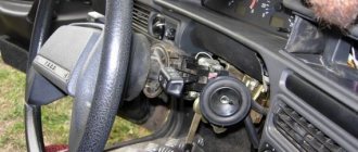
In addition, thanks to the installation of a new cabin with increased functionality on the chassis, the electrical wiring of the GAZ 3307 was also modified. This was required by the appearance on the car:
- Efficient ventilation and heating systems;
- Power steering;
- New instrument panel.
Electrical equipment
As for the electrical equipment, in connection with the manufacturer’s experiments trying to select the optimal power unit, the engine compartment wiring of the GAZ 3307 also underwent modernization.
- Instead of the previously used DC generator, the car received an alternating current generator model G250-G2;
- To protect the electrical equipment, a voltage regulator model 222.3702 was integrated.
Caution: Do not start the engine if the cable from the generator to the regulator is damaged, as well as checking for a spark. The electrical circuit is not designed for such loads, so it will fail during any attempt to start or test.
The ignition system has also undergone a slight modernization:
- Instead of the old B114-B ignition coil, a more powerful B116 was installed;
- The old distributor R133-B was replaced with a modernized 24.3706;
- An electronic ignition switch model TK102A appeared. Later, instead of it, the car was equipped with a universal switch 13.3734, as well as its modification - 13.3734-01;
- The circuit uses a resistor SE107, and on a number of models the universal 14.3729 was installed (see also the Gazelle wiring diagram).
Ignition system components 3307
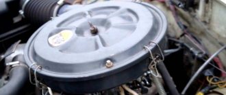
Accumulator battery
The manufacturer provides the 6ST-75 as a battery, modifications of which are available from many domestic manufacturers.
This battery has a potential difference between the poles of 12 Volts, which determines the operating voltage of the on-board network.
The standard GAZ 3307 battery is considered to be a 6ST-75 battery.
Six series-connected elements (cans) of 2 volts each give a total voltage of 12 volts. The nominal battery capacity is 75 ampere-hours. The starting current can be from 640 to 750 Amps depending on the model.
The cost of a new battery depends on the manufacturer and ranges from 3-5 thousand rubles; a used one can be purchased much cheaper.
Starter
In addition to the battery, the ignition system also includes other units. The 230-A1 starter, which is used in a very large number of equipment based on GAZ vehicles, is directly involved in the appearance of the first spark.
This is what a starter for a GAZ 3307 looks like
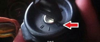
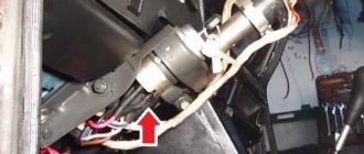
Egnition lock
The GAZ 3307 ignition switch is designed to turn on and off the ignition circuit, as well as other energy consumers. It has four positions, five contacts. Designed for a rated current of 15 (7.5) amperes and a voltage of 12 (24) volts. This lock is also used on KAMAZ vehicles and PAZ buses.
Ignition coil
To generate a high-voltage pulse, the B114-B ignition coil is used (or on newer models B116 can be used), after which the pulse from the coil is distributed through the TK102A ignition switch (or universal 13.3734 or its modification 13.3734-01 can be used).
The ignition coil is 3307 cylindrical type; in older ignition systems the B114-B model was used.
Example of an ignition coil for gas 3307
Distributor
The breaker-distributor for the GAZ 3307 contactless system works with an 8-cylinder engine, the spark alternates evenly every 45 degrees. The distributor consists of a housing, a roller (rotor) with a centrifugal regulator and a magnet, a stator, a vacuum regulator, a slider and a cover. The shaft is driven by the camshaft through the chopper-distributor drive. The distribution among the cylinders is in the order 1-5-4-2-6-3-7-8.
Switch
The switch is designed to provide a powerful impulse regardless of engine crankshaft speed, thereby facilitating ignition of the fuel mixture. There are two types of switches on the GAZ 3307. Model 13.3734-01 is used on systems with a variator; in later ignition schemes without a variator, switch 131.3734-11 is installed. Switches are not interchangeable with each other.
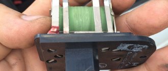
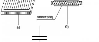
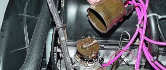
Variable speed drive
The variator (or additional resistance) is designed to limit the current in the primary circuit of the ignition coil at low engine speeds, thereby protecting the coil from overheating. When the engine starts, the variator is bypassed and does not limit the current. At high speeds, the resistance of the variator decreases, and the current does not weaken, which allows maintaining a high voltage in the secondary circuit.
An example of a variator installed on a truck body
source
Verification methods
Given the external similarity of the electrical equipment, the automaker reasonably assumed the possibility of errors when servicing the car independently, the price of which was high. Therefore, I provided automatic protection of elements from accidental short circuits:
- The generator excitation winding circuit is protected using a protection relay, as well as a separating diode;
- While the engine and generator are running, the relay contacts are open;
- If a wire breaks or short circuits, the current flowing through the relay winding will increase;
- The opposing winding will create a magnetic field, the core will retract and open the relay contacts (see also the VAZ 2101 wiring diagram).
To check the serviceability of the protection you must:
- Turn off the engine;
- Turn on the ignition;
- Connect the voltage of the relay-regulator to ground;
- Alternately press the anchors RN and P3, closing their contacts.
If the relay is working properly, the voltmeter needle will move to the “0” mark. If this does not happen, the transistor is faulty and the relay regulator must be replaced.
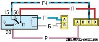
Connecting the ignition switch gas 3307
First of all, let's get acquainted with the ignition system of the GAZ-3307 truck. The ignition system of the GAZ-3307 is battery-based, contactless transistor with a voltage in the primary circuit of 12V, consists of electric current sources, an ignition coil, an additional resistor (if I’m not mistaken, where since 2000 they have been produced without an additional resistor), a switch, an ignition distributor, spark plugs, plug tips, ignition switch and low and high voltage wires.
Technical characteristics of the ignition system of GAZ-3307 (GAZ 53) cars
Ignition order of GAZ-3307 1 - 5 - 4 - 2-6 - 3 -7 - 8 Type of ignition distributor (distributor) - 24.3706 Distributor shaft rotation speed per 1 min with uninterrupted spark formation when working with a B116 ignition coil on a three-electrode spark gap at spark gap 7 mm, min-1 - 20 - 2300 Direction of rotation of the ignition distributor roller (distributor) GAZ-3307 - clockwise Ignition coil GAZ-3307 - B116 Spark plugs - A11 Spark gap size in spark plugs, mm - 0.8 - 0.95 Additional resistor - 14.3729 Switch - 131.3734 or 13.3734 Spark plug tip - 35.3707200
Diagram of the GAZ-3307 ignition system
And so, as I already said in our time, the ignition system of the GAZ-3307 truck has undergone minor changes.
As I already wrote, this happened after 2000, this is approximately what I am saying. I can’t say for sure, I’m afraid I’ll make a mistake, but I didn’t bother googling and searching for it; I just don’t have time for it and it’s not particularly interesting. If you are interested, look for it and then share it with me. You can leave a comment.
This applies to transistor switch brands 13.3734 and 131.3734
You can see the difference is just one number, that is, it was 13.3734 before 2000, but they began to produce the GAZ-3307 after 2000 with a switch of 131.3734. And so there is only one number and this is one number, that is, as you noticed, number 1 removes the additional resistor from the GAZ-3307 ignition system - 14.3729.
That is, simply put, the function of the additional resistor is 14.3729. built into the transistor switch 131.3734.
I want to warn you, someone may say “yes, I put brand 13.3734 instead of brand 131.3734 and why doesn’t the machine work?” I agree with him.
GAZ-3307 will of course work and go normally, but not far. Why, you ask, of course, and you will be right, you need to find out why ? Yes, because your ignition coil (bobbin) will simply burn out.
Why this will happen : The ignition coil, GAZ-3307 (B 116) is a transformer, on the iron core of which the secondary winding is wound, and on top of it is the primary winding. The core with windings is installed in a sealed steel case filled with oil and closed with a high-voltage plastic cover.
Operating temperature from -50° C to +80° C. Resistance value at a temperature of 25° C: primary winding (0.65+0.07) Ohm, secondary winding (18+1.8) kOhm.
Developed secondary voltage 18 kV max. Supply voltage 12 V. Weight 0.95 kg. During operation, the B-116 ignition coil is supplied with reduced voltage through an additional resistor-14.3729 . The resistor heats up during operation, this is normal. The resistor, when the starter is turned on (when starting the engine), is bypassed and the coil is supplied with full voltage (more precisely, the on-board voltage supplied by the starter), this makes starting easier.
the additional resistor 14.3729 takes up “work” again . And now give yourself this picture of a GAZ-3307, well, let’s say after the year 2000, there is, of course, ignition without an additional resistor - 14.3729 and an ignition coil B-116 and a transistor switch 131.3734, and you took and installed a transistor switch 13.3734, and what next GAZ-3307 Of course, it will start; moreover, it will drive normally (as I already stated above), but the coil will not burn out very far. That is, there is no one to lower the on-board voltage for the ignition coil.
And as we already know, the B-116 ignition coil is powered by a reduced voltage through an additional resistor-14.3729 or with an added voltage reduction function in a transistor switch brand 131.3734.
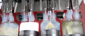
Operating principle of the ignition system 3307
The operation of the ignition system 3307 is built according to the classical scheme. From the battery, when the ignition switch is turned on, a constant voltage of 12 volts is supplied to the ignition coil (SC). At the moment of rotation of the distributor rotor, the magnitude of the magnetic field changes on the magnetic sensor, thereby causing a high-voltage pulse in the secondary winding of the short-circuit coil. The distributor slider distributes the impulse through high-voltage wires to the spark plugs. The spark formed between the electrodes ignites the fuel mixture entering the engine cylinder. The engine cycle is in progress.
Purpose of the ignition switch
The ignition switch (or ignition switch) is the main switching component that turns the engine and the entire electrical system of the vehicle on and off. Typically, the ignition switch solves several main problems:
- Connecting/disconnecting the vehicle's electrical system to the battery and (after starting the engine) to the generator;
- Connecting/disconnecting the ignition system (its primary low-current circuit) of the engine to the power source;
- Short-term activation of the starter (during engine starting);
- Ensuring the operation of some current consumers (radio tape recorder, anti-theft alarm and others) when the engine is not running;
- Performing the functions of an anti-theft device (steering wheel lock) when the engine is not running.
Thus, the ignition switch is necessary not only to start the engine, but also to turn on and off the entire on-board electrical system of the car, and to protect the vehicle from theft. However, with such a wide functionality, the ignition switch has a fairly simple structure and operating principle, and there are not too many types of locks today.
Types of ignition switches
All ignition switches are divided into several categories according to type, purpose and functionality.
There are two main types of ignition switches:
- With key;
- Keyless (ignition switches).
Key locks are the most common today and are installed on most cars and other vehicles. Keyless ignition switches were especially common in the early days of the automobile industry, and were installed on cars (especially trucks) into the 1940s and 1950s. Switches were then replaced by key locks, but today ignition switches are making a comeback. Modern keyless switches are more technologically advanced than the regular buttons found on older cars, but their functions remain roughly the same.
All existing ignition locks can be divided into two large groups according to the number of key positions:
- Locks with three key positions;
- Locks with four key positions.
Locks with three key positions are out of use today; they can only be found on older models of cars and trucks, especially domestically produced ones. Since the 1960s and 1970s, new four-position locks have been installed on cars, which have expanded functionality. The functionality of ignition switches will be discussed in more detail below.
Also, ignition locks can be divided into two groups according to the presence of an anti-theft system:
- Conventional locks without steering wheel lock;
- Locks with mechanical steering wheel lock.
The steering wheel is locked by almost all ignition locks with four key positions; old three-position locks do not have this function.
Finally, ignition locks can have various additional functionality, including protection against turning on the starter while the engine is running, a warning system for a key left in the lock, and others.
Regardless of the type and purpose, all ignition switches have fundamentally the same design and operating principle.
About the engine
During its production, the GAZ-3307 car was equipped with various models of power units. This approach made it possible to select the appropriate engine for each modification of the vehicle.
Manufacturers produce the following types of motors:
- injection;
- carburetor;
- diesel
It is noteworthy that the type of engines varied depending on the year of manufacture of the vehicle. Each unit is worth considering in more detail.
Carburetor
The most popular engine used on this vehicle is ZMZ-5231.10. The motor design includes 8 cylinders and a liquid cooling system that prevents overheating of the device when heavy loads occur.
Main characteristics of the motor:
- weight – 2.75 t;
- volume – 4.67 l;
- fuel - A-76, AI-80.
A key feature of the power unit is the ability to improve the ignition system, which many drivers seek to take advantage of. This type of engine is in demand on trucks.
Injection
Such motors were used for the first time in 2021. The devices are classified as V-shaped. The volume coincides with that specified in the carburetor versions of the engines. The maximum weight reaches 3.275 tons.
Diesel engines
First of all. It should be noted that diesel types of units are numerous. There are three modifications of engines for the GAZ-3307, and each has its own pros and cons.
The first engine produced was the MMZ D-245.7E4 turbocharged diesel unit. The advantage of the device is the presence of a cooling system. The volume is 4.75 liters, and the power reaches 125 hp. The maximum weight of the unit is 430 kg.
The second engine was YaMZ-5344, the design of which also includes 4 cylinders. The power indicator is within 134 hp, and the total volume is 4.4 liters. The engine was first used in 2013. Now it can be found on many trucks.
The modern model of power devices is YaMZ-53443. It was released in 2021. A special feature of the engine is improved power, which reaches 146 hp. However, the volume of the unit did not change.
Ignition switch device
The ignition switch consists of two connected units:
- A cylinder lock (cylinder) with which an individual key is used;
- A contact unit that is connected by a leash to the lock.
Ignition locks use conventional cylindrical locks (cylinders), which allow simultaneous solving of two tasks - turning the contact assembly and locking the steering wheel. To lock, a special locking rod is used, which, when the key is turned, moves out of the lock body and falls into a special groove in the steering column.
1 - locking rod; 2 — ignition switch housing; 3 - roller; 4 - contact disk; 5 — contact sleeve; 6 — block; a - wide protrusion of the contact part;
The cylinder, connected to the leash, is installed inside a wide cylindrical spring, one end of which is fixed to the cylinder and the other to the lock body. The spring ensures automatic return of the lock after turning on the ignition (or if the engine starts unsuccessfully).
The lock's drive ensures not only rotation of the contact unit disk, but also fixation of the lock in the required position. For this purpose, the wire is made in the form of a wide cylinder, in which a through radial channel is provided. On both sides of the channel there are balls, between which there is a spring - with the help of a spring, the balls are pressed into the holes provided on the inner surface of the lock body, ensuring fixation. But with some effort, the balls come out of the holes and allow the lock to be moved to another position. There is no fixation only in the position in which the engine is started.
The contact assembly consists of two main parts - a movable contact disk and a fixed (connected to the lock body) block with exposed contacts. The disk contains conductive plates, which, when the key is turned, close certain contacts on the block - this ensures the closure of the car's electrical circuits.
There can be from 4 to 6 or more contacts on the block, all of them come out from the back side of the block (at the bottom of the ignition switch), and are connected in one way or another to electrical circuits. Modern locks use plate contacts to which one connector is connected. Previously, terminals in the form of bolts and nuts were widely used, but this solution complicates the installation of the lock and is not used today.
The lock and contact assembly are placed in a common (usually metal) housing. The lock is installed on the steering column or dashboard (if a mechanical steering wheel lock is not provided) using a decorative nut. In many domestic cars, until the early 90s, the lock was located to the left of the steering wheel (for example, on the VAZ Classic, most Moskvich models and others), today on most cars and trucks of domestic and foreign production the lock is installed to the right of the steering wheel . Moreover, the lock on the right is installed on both left-hand drive and right-hand drive modifications of foreign cars.
Electrical wiring and equipment diagrams for GAZ 3309
The equipment of diesel trucks includes:
| Number on the diagram | Item Description |
| A8 | Engine pre-heater unit, installed as a separate order |
| A10 | Heater |
| IN 1 | Oil operating pressure meter |
| AT 2 | Extremely low oil pressure alarm |
| AT 7 | Measuring element in the engine cooling system |
| AT 8 | A special element designed to signal engine overheating |
| AT 12 | Measuring element in the fuel tank |
| B19 | Air filter cavity clogging sensor |
| B31 | Emergency pressure sensor in the primary circuit of the brake system |
| B32 | A similar element in the second circuit |
| B61 | Preheater overheat indicator |
| B67 | Fluid level sensor in hydraulic brake drive |
| B97 | Primary circuit pressure measuring device |
| B98 | Similar detail of the second circuit |
| B99 | Measuring device for the emergency condition of the piston stroke in the pneumatic brake booster (primary circuit) |
| B100 | A similar part in the second circuit (right side) |
| B101 | A similar part in the second circuit (left side) |
| D25 | Controller for electric headlight angle adjustment |
| E1 | Left headlight |
| E2 | Right headlight |
| E5 | Left front combination light (side light and turn signal) |
| E6 | Similar element on the right |
| E9 | Turn direction repeater mounted on the surface of the right wing |
| E10 | Identical unit on the left wing |
| E11 | Contour lighting lamp on the cab roof (left side) |
| E12 | A similar detail on the right side of the cabin |
| E16 | Cabin interior lighting |
| E27 | Tail light on the left side of the truck |
| E28 | A similar unit on the starboard side |
| E29 | Reverse indicator light |
| E31 | Rear fog light |
| E33 | Left rear contour light |
| E34 | Similar detail on the starboard side |
| E35 | Engine compartment lighting lamp |
| E37 | Front left side signal |
| E38 | Right side marker light on the front |
| E39 | Side marker to indicate the rear left side of a truck |
| E40 | Identical element on starboard side |
| E50-E53 | Individual glow plugs (4 pcs.) |
| E54 | Starter plug used when igniting an autonomous heater |
| E73 | Left indicator light module |
| E84 | Similar element on the right side |
| F26 | Thermal fuse to protect the preheater |
| F41 | Power fuse module in the engine compartment |
| F42 | Upper section of the cabin fuse block |
| F43 | Similar bottom part |
| G1 | Generator |
| G2-G5 | Batteries (4 pcs.) |
| H1 | Left horn |
| H2 | Right beep |
| H3 | Buzzer signaling a drop in air pressure in the pneumatic system |
| H7 | Low engine oil pressure warning light |
| H8 | Power unit overheat indicator |
| H9 | Light warning signal for overheating of the autonomous heater |
| H11 | Air filter clogged with dust lamp |
| H16 | Display of direction indicator operation (on base chassis) |
| H19 | Indicator of emergency fuel remaining in the tank |
| H20 | Displaying the operating mode of headlights with high beam |
| H30 | Parking brake warning light |
| H37 | On-board pre-heater operation indicator |
| H39 | Signal of a breakdown of the standard ABS system in the brake drive |
| H44 | Separate lamp for illuminating the pressure indicator in the primary circuit of the brake system |
| H45 | A similar device for the secondary circuit device |
| H47 | Illumination lamp for displaying the fuel level in the tank |
| H48 | Ammeter illumination in instrument cluster |
| H54 | Voltage drop indicator at battery terminals |
| H56 | Low Brake Fluid Level Warning Light |
| H62 | Signal lamp on the front of the truck |
| H66 | Speedometer dial illumination system |
| H67 | Lighting of the instrument displaying engine temperature |
| H68 | A similar device for illuminating the oil system pressure gauge |
| H69 | Tachometer light |
| H74 | Lamp in the rear light warning of the start of braking |
| H76 | Signal lamp on the rear of the machine |
| H78 | Turn signal lamp (on rear of truck) |
| H80 | Indicator for turning on external side lighting |
| H96 | Pre-heater spark plug warning light |
| H98 | Low beam filament |
| H100 | High beam lamp filament |
| H102 | Direction indicator lamp (in front lamp) |
Operation of the ignition switch
In general, the operation of the ignition switch is extremely simple: when you turn the key, the contact disk rotates and certain electrical circuits of the car are closed. Moreover, turning the lock is possible only when using an individual key; it is impossible to start the car with another key.
Ignition switches can have three, four or five positions:
- “Off” - in domestic ignition switches it is designated as “0”, although in some older cars this lock position was designated “I”. In modern foreign-made cars, this position is not fixed or indicated on the lock;
- “On” or “Ignition” - in domestic locks it is designated as “I”, although sometimes “II” is also found (in Moskvich cars), in modern cars this position is designated “ON” or “3”;
- “Starter” - in domestic cars it is designated as “II”, on some models you can find the designation “III” (in Moskvich cars), in modern cars it is designated “START” or “4”;
- “Locking” or “Parking” - in domestic cars it is designated as “III”, sometimes as “IV” (in Moskvich cars), in foreign cars it is designated “LOCK” or “0”;
- “Additional equipment” - in domestic ignition switches there is no such position; in foreign cars it is designated as “Acc” or “2”.
Correct operation and repair of the ignition switch
The operation of the ignition switch has several subtleties that especially need to be taken into account in older cars. It is important to remember the following:
- The key must be turned smoothly and without jerking, and the key must not jam or slip (if this happens, the lock must be checked and repaired);
- Do not turn the key to the “Stater” position when the engine is running, as this may lead to damage to the starter. Many modern locks have a function to block the key from turning when the engine is running;
- Do not leave the ignition key in the “ON” position when the engine is stopped, as this will discharge the battery;
- To lock the steering wheel, you must first remove the key and then turn the steering wheel in one direction or another until it stops.
Some cars have other features of the ignition switch; they must be indicated in the operating instructions.
The ignition switch is one of the most reliable parts of a car, but over time it can also fail. The most common problems encountered are jamming of the cylinder, wear of the cylinder, wear and corrosion of contacts, or mechanical damage to the contact unit. If the cylinder fails, the lock is replaced completely; if the contact unit breaks, only it can be replaced without touching the cylinder. However, today, in case of any malfunction, the lock is most often replaced completely, since this is easier and cheaper than disassembling and repairing the old lock.
It should be noted that some problems can be solved without replacing the lock. For example, if the lock jams, especially on domestic cars, you can try treating the cylinder with graphite lubricant. And damage to contacts or conductors in a contact assembly can be repaired by soldering or replacing these parts.
In general, the ignition switch usually does not cause problems for the car owner; in good condition, it provides easy operation and protection against theft, and lasts for many years.
If the engine does not start, but there is a spark on the center wire.
In this case, there may be a malfunction of the distributor slider, that is, its breakdown or burnout of the resistance due to radio interference.
To check the slider for breakdown, simply place a high-voltage wire from the coil onto the distributor above the slider and crank the engine with the starter. In this case, it is necessary to take precautions against electric shock; it is not fatal, but very unpleasant. If a spark jumps between the wire and the slider, the slider must be replaced. If the spark does not jump, then check the serviceability of the resistance installed in it.
There may be other malfunctions in the ignition system, but with them the engine will start, but it will run unstably or stall.
admin 10/12/2017
“If you notice an error in the text, please highlight this place with the mouse and press CTRL+ENTER” “If the article was useful to you, share the link to it on social networks”