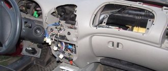
The essence of the recording is clear from the title. The BSK has not worked since I bought the car; in principle, I didn’t really need it, but if it’s in the car, then it should work. The probability of the block itself breaking seems to me to be 1 in 1000. In principle, there is nothing to break there. I was sure that either the wire block was not connected to it at all, or there was no 12V coming to the unit. After disassembling the panel and freezing the block, I got to the block. I was so carried away by the process that I didn’t take any photos of the disassembled panel) I found the pinout on the Internet and rang it with a multimeter. Pin 9 (diagram below) does not receive positive from the ignition switch. That's what I thought) There was no desire to change the lock or do anything with the old one, and I decided to go a different route. I simply connected pins 13 and 9 with a wire in the block
These are the contact details
I didn’t take a photo of the block itself, and I couldn’t find it on the Internet either, so I showed it on the block itself
in reality it looks like this. the quality of the photos sucked because I only had a phone with no autofocus on hand
Now everything works properly, the squeaker just infuriates) it was better without it)
Why does the VAZ 2114 instrument panel not work? A massive problem in our auto industry
The search for possible reasons why the VAZ 2114 instrument panel does not work periodically worries one or another owner of cars of this model.
It’s clear that if you don’t see a single parameter on the dashboard, you can only drive, as they say, by touch. True, there are certain specialists who still managed to somehow crawl to the base without all the evidence, but somehow I don’t want to follow their example. And is it necessary to create additional troubles and the risk of accidents on the road? So the majority of those to whom this incident happened still get to work (or wherever they were going) by public transport in order to return to solving the problem in the evening on their own or with the help of a familiar mechanic.
Why does the VAZ 2114 instrument panel not work? Offhand, we can name several reasons. However, they may not exhaust the entire list, since the individual characteristics of the car may appear. We will try to talk about this and many other equally interesting things in our article today.
Checking the display unit of the on-board control system of the VAZ 2115 Lada
- Repair manuals
- Repair manual for VAZ 2115 (Samara 2) 1997+.
- Checking the on-board control system display unit
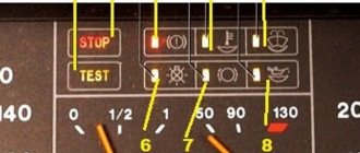
The unit can be in one of five modes:
– off;
- waiting mode;
– preliminary control of signaling devices (testing);
– preliminary control of parameters (state of sensors);
– control of parameters during engine operation.
When opening any car door, the unit must turn on the interior lighting.
Off mode
When the key is not inserted into the ignition switch , the unit is in the "off" mode.
Waiting mode
After inserting the key into the ignition switch , the unit goes into “standby mode” and remains in it as long as the key in the ignition switch is in position 0 (“Off”).
If the driver's door is open in this mode, the “Forgotten key in the ignition switch” malfunction occurs and the audible warning light begins to emit an intermittent sound signal for (8±2) s. The signal should turn off if you close the door, or remove the key from the ignition switch, or turn the key to another position.
Testing
This mode is activated after turning the key in the ignition switch to position I (“Ignition”). In this case, the sound alarm and all LED indicators should turn on (4±2) to check their serviceability.
At the same time, faults are monitored by level sensors and their status is stored. The sensor status is not signaled until testing is completed.
Pre-departure
control of parameters
After testing is completed, there is a pause and the unit goes into pre-departure control of parameters. In this case, fault signaling (if any) is carried out according to the following algorithm:
– LED indicators for those parameters that are outside the normal range begin to blink for (8±2) s, after which they begin to light continuously until the key in the ignition switch is turned to position “0” (“Off”);
– simultaneously and synchronously with the LED indicators, the sound indicator turns on and turns off after (8±2) s.
Monitoring parameters
during engine operation
The unit enters this last mode after the end of the previous mode. In this case, monitoring of level sensor parameters stops and only other parameters are monitored.
If a malfunction occurs while driving, the alarm is repeated according to the algorithm given for the “Pre-departure parameter control” mode.
If during the sound and LED alarms the key in the ignition switch is turned to position “0” (“Off”), then the sound and light alarms should turn off.
If malfunctions such as “Wear of the brake pads” or “Burnout of lamp filaments” occur, the malfunction must be stored until the end of the trip [until the key is turned to position “0” (“Off”)].
If within (8±2) s after the start of the light and sound alarm, one or more “Fault” signals appear, then the flashing light indication should light up steadily, and the light indication of newly received signals should turn on according to the described algorithm.
↓ Comments ↓
1. General information
1.0 General data 1.1 Technical characteristics of vehicles 1.2. Vehicle controls 1.3. Vehicle operation 1.4 Vehicle maintenance
2. Engine
2.1 Possible malfunctions, their causes and methods of elimination 2.2 Removal and installation of the power unit 2.3 Disassembly and assembly of the power unit 2.4 Disassembling the engine 2.5 Assembling the engine 2.6 Running in the engine after repair 2.7 Checking the engine on the car after repair 2.8. Cylinder block 2.9. Connecting rod and piston group 2.10. Crankshaft and flywheel 2.11. Cylinder head 2.12. Camshaft and its drive 2.13. Lubrication system 2.14. Cooling system 2.15. Supply system
3. Transmission
3.0 Transmission 3.1. Clutch 3.2. Gearbox 3.3. Front wheel drive
4. Chassis
4.0 Chassis 4.1. Front suspension 4.2. Rear suspension
5. Steering
5.0 Steering 5.1. Features of the device 5.2 Possible malfunctions, their causes and methods of elimination 5.3 Inspection and testing of the steering control of the car 5.4. Removal and installation 5.5 Checking the gap between the rack stop and the nut 5.6. Disassembly, technical condition check and assembly 5.7 Replacing the rivets of the elastic coupling of the steering shaft
6. Brake system
6.0 Brake system 6.1. Features of the device 6.2 Possible malfunctions, their causes and methods of elimination 6.3. Checking and adjusting brakes 6.4. Vacuum booster 6.5. Main cylinder 6.6. Pressure regulator 6.7. Front wheel brake 6.8. Rear wheel brake 6.9. Dismantling and assembling wheel cylinders 6.10. Parking brake system
7. Electrical equipment
7.0 Electrical equipment 7.1. Wires and fuses 7.2. Battery 7.3. Generator 7.4. Starter 7.5. Lighting and light signaling 7.6 Sound signal 7.7. Windshield cleaner 7.8. Heater fan electric motor 7.9. Electric motor of the engine cooling system fan 7.10. Instrument cluster 7.11. On-board control system display unit 7.14. Electric windows and front door lifts 7.15. Door lock system
8. Body
8.0 Body 8.1. Device Features 8.2. Body frame repair 8.3. Paint and varnish coatings 8.4. Anti-corrosion protection of the body 8.5 Sealing of the body 8.6. Doors 8.7. Hood, trunk lid, bumpers 8.8. Body glazing 8.9. Instrument panel, seats 8.10. Heater
9. Cars VAZ-2115-01, VAZ-2114-20
9.0 Cars VAZ-2115-01, VAZ-2114-20 9.1. Car VAZ-2115-01 9.2. Car VAZ-2114-20
10. Applications
10.0 Appendices 10.1 Appendix 1. Tightening torques for threaded connections 10.2 Appendix 2. Special tools for repair and maintenance 10.3 Appendix 3. Basic data for adjustments and monitoring 10.4 Appendix 4. Fuels and lubricants and operating fluids
The most common breakdown
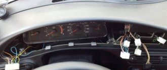
Before digging into the inside of the car, check how securely the ground wire leading to the front panel is secured. A restless passenger in front often simply pulls him out of his place with his feet. To prevent the situation from repeating itself, after fastening it is worth insulating the wire from reach.
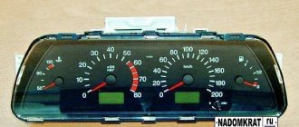
Its signs are very characteristic:
- All indicators do not work: speedometer, tachometer, odometer, fuel level recorder, coolant temperature sensor;
- The rest of the equipment - optics, radio, even the panel backlight - turn on normally and do not act up;
- The ignition works properly, the car does not refuse to start;
- Fuse F3 is almost 100% blown. It is located in the mounting block and will have to be changed. But first you need to find out why it was covered, otherwise the new one installed will suffer the same fate. In most cases, a short circuit is to blame for burnout. On well-used VAZ-2114, the fuse often blows after each wash. Instead of carrying a spare one, you need to figure out where moisture is getting into it.
If the fuse is intact , this is not a reason to immediately leave it alone. It would be a good idea to remove it and check the contacts: if the fuse is live, but the terminals are oxidized, the circuit will be interrupted, and the device will stop showing any signs of life.
The next weak link : It is the ignition relay. It is located to the left of the steering column, fixed on a pin, so to speak, upside down. You need to remove it and try to make direct contact with the wires. If there are obvious signs of revival on the instrument panel, it immediately becomes clear that the time has come to change the relay.
How to connect BSK VAZ 2114
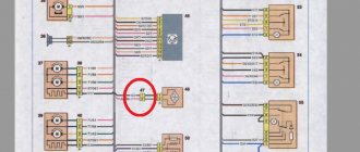
Electrical diagram of Lada Samara 2 cars (left half): 1 – headlights; 2 – fog lights; 3 – air temperature sensor; 4 – electric motor of the engine cooling system fan; 5 – blocks connected to the wiring harness of the ignition system; 6 – engine compartment lamp switch; 7 – block for connection to a single-wire type audio signal; 8 – sound signal; 9 – washer fluid level sensor; 10 – front brake pad wear sensors; 11 – oil level sensor; 12 – generator; 13 – engine compartment lamp; 14 – coolant temperature indicator sensor; 15 – starter; 16 – battery; 17 – relay for turning on fog lights; 18 – coolant level sensor; 19 – brake fluid level sensor; 20 – reverse light switch; 21 – windshield wiper gearmotor; 22 – oil pressure warning lamp sensor; 23 – block for connecting to the rear window washer electric motor; 24 – windshield washer electric motor; 25 – instrument cluster; 26 – mounting block. Conventional numbering of plugs in blocks: A - block headlights; B — electric fuel pump block; C — blocks of the mounting block, ignition switch, windshield wiper gearmotor; D — interior lamp
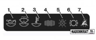
The unit contains an electronic control circuit with an audible alarm and 7 LED indicators: insufficient oil level, insufficient washer fluid level, insufficient coolant level, open doors, faulty exterior lighting lamps, worn linings on the front brake pads and unfastened seat belts. Addresses of block plugs VAZ 2114, VAZ 2115, VAZ 2113. The order of conditional numbering of block plugs is similar to the numbering order of plugs in the instrument cluster blocks.
Addresses of the output plugs of the on-board control system display unit
The topic may be hackneyed, but when I started looking for information on how to do this, I mainly came across connecting the emergency lights and an article about connecting new buttons on the 2110.
Let me start with the fact that recently I became the proud owner of 14 panels at a reasonable price)
I threw it in pretty quickly, took half an hour to remove the old one, and about the same amount of time to push this one in (I had the wiring and lock left over from the carb version of my car), then the question arose with connecting the shield (which a Google search actually did a very good job of (plenty of information) and the method of scientific poking). Actually, the easiest part is over, hemorrhoids began with connecting the paired button for external lighting, as I already said, I did not find a clear and adequate answer on how to connect the 09 wiring with this button (H3, maybe I was looking crookedly, but oh well)))), using the method I managed to connect this device with a scientific poke and a tester. Below is the exterior lighting button block 2109, the pinout is indicated by wire colors for convenience)))
Now the external lighting button is 2114, pinout is according to the wiring colors 2109)))
Contacts A and E must be connected to each other in order for the low beam switch to light up)
Let's move on to buttons 2109 for heated glass and fog lights, the pads for these buttons look the same
where 1, 2 are contacts that can be closed to turn on the button, a, c are the button illumination (turned on with the dimensions) c, d is a separate wire for indicating the button’s activity (located separately from the main block).
To begin with, here is the following diagram (in principle, it’s easy, we look for the button we need, look at the colors of the wires and screw it to the new button)
Sorry for the signatures of the letters above, I signed for myself in the absence of a color printer)))))
Well, the actual pinout of button 2114 (fog lights and heating are connected in the same way)
a, c — button indication (lights up along with the dimensions), c, d — button activity indication (lights up when turned on).
Well, connecting BSK 2114 to wiring 2109
Let's start with the pinout of the terminals.
Terminal BSK 2109 (9 pin)
And terminal BSK 2114 (13 pin)
1 Oil level 2 To the coolant sensor 3 To the washer fluid level sensor 4 Seat belts (if not, then screw them :-))) 5 To brake pad wear sensors 6 Driver's door switches 7 Passenger's door switches 8 Light switch circuit interior 9 The key is in the ignition switch (I have an old lock that doesn’t care about the inserted key, so I removed contact 9 from the orange wire of the red block (constant +) I know it’s not right, but what can you do) 10 Relay for monitoring the health of the lamps 11 Ground 12 ХЗ (not used) 13 To the ignition switch terminal
to connect the BSK 2114, due to the fact that I have the wrong lock and terminal 9 is removed from the permanent + on the red block, the BSK starts working after you start the engine.
I'm searching Google for a wiring diagram for BSK 2114 to 2109, but if you connect it according to that diagram, the starter continues to turn even after you throw the key. Here's the diagram
This happens due to the fact that contacts 9 and 13 are closed to each other, which is apparently not correct, and actually I couldn’t connect using this diagram (((so it’s easier to print out the pinout of both blocks.
Well, in the epilogue, the wires are short and need to be extended, here you should not be lazy and use a soldering iron and heat shrink, yes, it takes more time, but it will look good)))
PS If anyone knows how to make the BSK work with the old lock immediately when you turn the key and not cause any problems, such as a constantly spinning starter, please write in the comments.
Well, that’s basically it, today it’s been run in and tested)
die Achtung: We supplement the article, the problem with the BSK is solved by switching the 13th block to the constant plus on the red block (orange wire) exactly the same wire that goes to pin 9 of the BSK)
Note: When the ignition is turned on, all indicator lamps of the on-board control system display unit should light up for 5-7 seconds. If this does not happen, then the display unit or its power supply circuit is faulty (see “Fuse and relay mounting block”, fuse F10).
Hard case
Until now, situations have been sorted out when the torpedo still showed some signs of life. If non-working power windows, turn signals, and windshield wipers have been added to the devices, the issue is no longer a matter of relays and fuses.
There may be 2 options:
- The contacts on the ignition switch are burnt. In principle, after installing the relay (even on the VAZ-2109 version), this problem rarely arises. However, the possibility remains. The lock is removed, the contacts are checked and, if necessary, cleaned;
- Mounting block. There may be burnt tracks on its board. The only thing that will save you is replacing it with a new one. However, the cost is by no means astronomical, and the installation is available as a standalone option.
Private situations
General signs do not always indicate specific breakdowns. There may be exceptions.
If individual devices refuse to work, it is quite possible that this is their personal problem. You'll have to parse the specific pointer. It may have a cracked gear that needs to be replaced.
Also, why doesn’t the instrument panel of the VAZ 2114 work? If the fuel gauge and tachometer are capricious (either they function, or they don’t react at all), the contacts and the mounting block are normal - you need to do a small check.
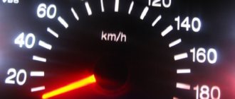
Reset is pressed and held, and the ignition is turned on at the same time. Raised arrows indicate the need for further searches. Lifeless - that microcracks have appeared in the shield itself. You will have to remove it and examine all soldering and traces under a magnifying glass. In principle, these are all the main options. If calling all the listed components and parts did not lead to the revival of the instrument panel, your case is individual, and you will have to determine the situation in the company of an experienced auto mechanic.
If you find an error, please select a piece of text and press Ctrl+Enter.
How to install an on-board computer on a VAZ 2114
Not so long ago, on Russian cars, all parameters were monitored by arrows on the instrument panel. Using the instruments, one could find out the speed, the presence of fuel in the tank, the temperature of the liquid in the cooling system, oil pressure, and charging. But all the data was quite approximate, and there were not so many parameters. Recently, many modern passenger cars have increasingly become equipped with more advanced control means, and there are more and more such devices. Nowadays, modern technology allows us to more accurately monitor the technical condition of a vehicle and timely identify any problems in it.
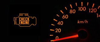
The on-board computer of the VAZ 2114 does not work reasons
Operating instructions for the VAZ-2115 on-board computer
Cars manufactured on the territory of the Russian Federation are equipped with a computer. The first on-board computer appeared on the VAZ-2114. In simple terms, the on-board computer can be considered a kind of electronic reference book on the condition of the car. The driver needs it in order to understand the condition of his car, as well as what faults have appeared in it.
The first on-board computers on domestic cars performed the following functions:
The modern on-board computer on the VAZ-2115 is designed for:
Among other things, depending on the vehicle’s configuration, its on-board computer may receive the following data:
PURPOSE OF THE ON-BOARD COMPUTER
An on-board computer on a car is an electronic computer device designed to monitor the status of various components of the car and transmit information to the car owner. Depending on the technical equipment, on-board computers (BCs) can vary in complexity, and accordingly, the price of the device can vary significantly.
The VAZ 2114 car is equipped with BC 2114-3857010 as standard from the factory. The device is mounted on the panel to the right of the instrument cluster at the same level with it. On those VAZ models that are not equipped with such a device, there is a plug in the standard place on the instrument panel and there must be a 9-pin connector for connecting the device.
In the “native” BC 2114, you can view the following parameters on the display:
- Current time and date;
- Travel time excluding stops;
- Travel time, including stops;
- Gasoline consumption at the current time;
- Average and total gasoline consumption per trip;
- Mileage on the remaining gasoline in the tank;
- Signal when there is a minimum amount of fuel left in the gas tank;
- Total level of remaining fuel;
- Travel distance;
- Average speed during the trip;
- Vehicle network voltage;
- Signal when the mains voltage is below the permissible level.
The “Lux” package is equipped with an AMK-211501 on-board (or route) computer, which has added firmware that allows you to diagnose the electronic engine control system (ECM). But many owners of VAZ models 2113, 2114, 2115 are not satisfied with the standard equipment with its limited functionality, and they strive to install a more advanced BC with a larger set of controlled parameters. They can be understood - now there are many different models from different manufacturers.
The smallest BC State X-1M is made in the form of buttons.
BC State X-1M
It is mounted above the standard location of the trip computer instead of push-button plugs. Among the interesting additional functions of the device are:
- “Plasmer” – warming up the spark plugs before starting the engine;
- “Tropic” – the ability to change the temperature at which the fan turns on and thereby prevent engine overheating in hot weather.
In total, the device has 30 functions, and the BC costs about 1000 rubles. More expensive trip computers are installed in a standard place and are more functional. On the display of the Orion BK-46 model you can see up to 7 controlled parameters simultaneously, and when the battery is disconnected, all data is saved in memory in the device. The issue price is about 2500-2800 rubles.
One of the most advanced BC models for the VAZ 2114 is the “Gamma GF 415T”. Here you can see interesting features such as:
- Displaying three multi-displays on the screen at once;
- Non-volatile quartz watches;
- Informing about the need to change oils, filters, spark plugs, etc.
There are a lot of controlled parameters, the cost of a bookmaker is in the range of 4000-4600 rubles. Many systems are equipped with audible alerts, and these computers are very easy to use.
Operating principle of the on-board computer
Cars such as the VAZ-2109 were equipped with devices that acted as routers. Let us remember that these were carburetor cars. But the VAZ-2114 and 2115 began to be equipped with injection power plants, which required the use of a completely different type of device.
Therefore, the main functions of the on-board computer on these cars are diagnostics, as well as control of the operation of almost all vehicle systems.
The principle of operation of the on-board computer on the VAZ-2115 is as follows:
CONNECTION
The connection diagram for the on-board computer on the VAZ 2114 is simple - it does not require special training or special qualifications. Therefore, you can connect the on-board computer to the VAZ 2114 with your own hands; detailed instructions are always attached to each device.
The connection principle is the same for all BCs, so let’s take a closer look at how to install an on-board computer on a VAZ 2114:
- De-energize the car (disconnect the battery terminals).
- We remove the standard plug from the instrument panel.
- We find the 9-pin connector.
- Remove the plug for the diagnostic connector.
- Remove the lower left side of the center console on the instrument panel.
- We take a piece of wire (about 1 m long) and connect it according to the following diagram. This wire in the diagram is designated as K-line white. That is, we connect terminal “7” (Euro-3) or terminal “M” (Euro-2) in the diagnostic connector with terminal “2” in the BC block with a wire.
The top right shows the Euro-3 type diagnostic connector (newer version), the bottom right shows the Euro-2 connector. The wire connection to the connectors is shown below.
Connecting the on-board computer wire to the connectors We connect the BC connectors.
Connection of BC connectors on VAZ 2114
- We install the BC in its regular place.
That's all, the installation of the on-board computer on the VAZ 2114 has been completed.
Operating principle of the on-board computer
Cars such as the VAZ-2109 were equipped with devices that acted as routers. Let us remember that these were carburetor cars. But the VAZ-2114 and 2115 began to be equipped with injection power plants, which required the use of a completely different type of device.
Therefore, the main functions of the on-board computer on these cars are diagnostics, as well as control of the operation of almost all vehicle systems.
The principle of operation of the on-board computer on the VAZ-2115 is as follows:
Source
SETUP AND TROUBLESHOOTING
Setting up the on-board computer is not always required; for example, the BC 2114-3857010 is easy to use and requires almost no settings. Each device displays its own parameters, so you need to read the instructions for the BC and follow the recommendations from the manufacturer.
If the VAZ 2114 on-board computer does not work, you need to check:
Sometimes it is necessary to reset all data (fuel consumption, travel time, etc.). As a rule, the instructions contain instructions for this (usually a reset button). But if there is no instruction or it doesn’t say anything about it, then you can reset the indicators like this:
- Remove the BC and remove the connector for a while;
- Disconnect the battery terminals for a certain period of time.
The readings should reset to zero.
ERRORS
On the on-board computer you can read all the errors that occur in the ECM. Deciphering the VAZ 2114 error code follows certain codes. If there are no errors, the message “No errors” lights up on the display. The list of errors is large, so we will list only the most common error codes for the VAZ 2114:
- 0134 – no oxygen sensor activity;
- 0116 – coolant temperature sensor error;
- 0172 – enriched fuel mixture;
- 0300 - presence of misfires;
- 0340 – phase sensor is faulty;
- 0505 – failures in the XX regulator.
Errors on the VAZ 2114 on-board computer are reset according to the instructions for each specific model by pressing a button combination, but a general reset can be done by temporarily disconnecting one of the battery terminals.
On-board computer does not work on VAZ 2115
Operating instructions for the VAZ-2115 on-board computer
Cars from the Russian Federation are equipped with a computer. The first flight attendant appeared on the VAZ-2114. In common parlance, flatulence. This is a kind of electrical reference to the condition of the car. The fuel level sensor is lying down. The indicator on the field does not work linearly, UAZ Patriot. He needs a driver if you intend to understand the condition of his car and, of course, what problems have arisen here.
The first on-board computers on Russian cars did the following:
- Check the amount of fuel poured into the tank.
- An approximate calculation of the distance that can be covered with fuel remaining in the tank.
- Monitors the performance of engine coolant temperature and further prevents engine overheating.
A modern aircraft based on the VAZ-2115 is designed for:
- Transfer of information about indicators “online”;
- display information in the dashboard;
- displaying route characteristics such as current fuel consumption, travel time, number of kilometers traveled, etc.
- diagnostics of the engine condition with subsequent display error on the flight attendant.
Among other things, starting with the equipment of the car, there are options on its side:
- information about the time of further vehicle maintenance;
- information necessary to configure specific vehicle functions;
- warning about the continuation of the insurance policy;
- information from the organizer;
- characteristics when the fan automatically turns on in the cooling system.
How does the on-board computer work?
VAZ-2109 cars were equipped with devices that served as routers. Let us remember that these were carburetor cars. But the VAZ-2114, and not the 2115, began to be equipped with injection power plants, which required the introduction of completely different types of devices.
Therefore, the main functions of the aircraft on these vehicles are diagnostics, in addition to controlling the operation of almost all vehicle systems.
What to do if the on-board computer on the VAZ-2115 stops working
Sometimes it happens that even though the car is in full working order, the on-board computer completely refuses to work. What to do in this case?
Of course, you can try to fix the problem yourself. But it’s still much better if a real specialist does this. It is he who will be able to reliably determine the cause of the device malfunction.
But before going to the service center, the first thing to do is check fuse F3, which could simply have blown. It is installed in the power supply circuit of the VAZ-2115 processor. If, after replacing the fuse, the on-board computer still shows no signs of life, you can also check the connectors connected to it. We repeat that if you are not an electrician, and generally do not have much knowledge of electronics, this task should be entrusted to a professional.
Remember, any malfunction that the on-board computer shows can be eliminated, just like a breakdown of the on-board computer itself. But, as they say, it is better to prevent a problem than to solve it later. Therefore, each car should be kept in good condition, undergo technical inspection on time and replace spare parts that are out of order. Among other things, it is better not to allow spare parts to break at all, but to replace them as they wear out. Only in this case will driving the car be safe from a technical point of view, and during the trip there will be no emergency situations associated with improper operation of the car.
The serviceability of your car is a guarantee of the safety of both the driver and passengers.
There is a special offer on our website. You can get a free consultation with our corporate lawyer by simply submitting your question in the form below.
Five days ago I finished what I had been doing for a month... I was soaring that the BC screen was glowing green when the inscriptions were glowing red. Not in order! I was looking for how to do it, there is no information, only rare perverts do this. But one day I found an article that explained everything very clearly! A question came into my head: “Overexposure on the board! Why didn’t I think of it?!” I began to disassemble the BC and took it apart. To begin with, I soldered 3mm matte LEDs to SMD.
Then I began to think about how to get the screen.
I decided to follow the instructions in the article - bite off the legs with side cutters... In vain. After the first leg I bit off, the screen bent and cracked in the corner. Well yeah. Okay, it won’t be very noticeable, I take a second bite and it cracks in the middle!
After that, the work stopped - I searched for a donor for 2 weeks, found him for 700 rubles. I decided to desolder the screen with a DMMC soldering gun. The high temperature causes the screen to heat up and darken, but as soon as it cools down, the crystals return to normal. They soldered it in four hands, there is no photo of the process. Photos will not convey the subtlety of that moment. I will say this, very carefully, first heating one side gradually, I bent the screen with tweezers, VERY CAREFULLY, the tweezers are iron, and the screen is glass. But we still tore off one leg. I attached it back and then couldn’t even find where that leg was. Then again a downtime of 1 week. Either there is no time, then there is no desire. But when I started collecting, I collected until 4 in the morning. I found thin PCB and red diodes and began to come up with a board. The main question was how to arrange the diodes evenly and add more resistance for them. I didn’t read the article carefully... In the original, the author did it without resistance, because those screen legs are supplied with 3 V, but for some reason I thought that 12... Okay, I more or less made the circuit, etched it out, it didn’t work, I didn’t do it right. It worked the second time.