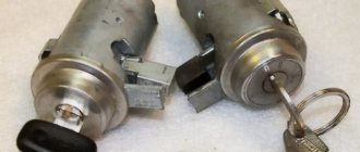
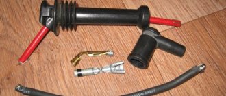
The ignition switch in cars of the VAZ family fails from time to time due to weakening of the contact posts or burning of the contacts inside it.
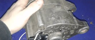
It also happens that the cams of a plastic roller are produced. You can disassemble the lock and clean it, but it’s better to just replace it with a new one, considering that it costs pennies compared to imported locks. But if connecting the wires together did not result in the starter operating (or it did not turn on the first time), check the solenoid relay on the starter. The contact spots on it may also burn out, which will prevent the circuit from closing normally. Alternatively, you can use a screwdriver to short-circuit the two large terminals on the solenoid relay (before doing this, put the car in neutral and use the handbrake). When closed, the starter should begin to spin vigorously. If this happens, remove and change the solenoid relay. If the starter rotates “sluggishly” when it closes, you will have to remove it and check the condition of the brushes.
All operations are performed with your own hands, without the help of car service specialists. Moreover, the price of an ignition switch on a VAZ2106 is up to 100 rubles. To replace it, you will need to know the pinout of the wires coming from it, for which the editors of the site 2 Schemes.ru have prepared a large reference material.
The ignition switch is designed not only to start the engine - it performs several functions at once:
- supplies voltage to the vehicle’s on-board network, closing the circuits of the ignition system, lighting, sound alarm, additional devices and instruments;
- at the driver’s command, turns on the starter to start the power plant and turns it off;
- turns off the power to the on-board circuit, preserving the battery charge;
- protects the car from theft by fixing the steering shaft.
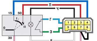
Pinout of the ignition switch VAZ-2101 - VAZ-2107
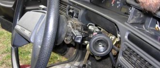
The ignition switch on these cars is located to the left of the steering column. It is fixed directly to it using two fixing bolts. The entire mechanism of the device, except for the upper part in which the keyhole is located, is hidden by a plastic casing.
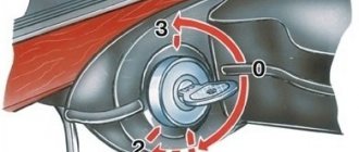
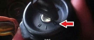
On the visible part of the ignition switch housing, special marks are applied in a certain order, allowing inexperienced drivers to navigate the lock activation mode when the key is in the hole:
- “” – a mark indicating that all systems, devices and instruments that can be turned on using the lock are turned off (this does not include the cigarette lighter, interior lighting, brake light, and in some cases the radio);
- “ I ” is a mark informing that the vehicle’s on-board network is powered from the battery. In this position, the key is fixed independently, and electricity is supplied to the ignition system, to the electric motors of the heater and windshield washer, instrumentation, headlights and light signaling;
- “ II ” – engine start mark. It indicates that voltage is applied to the starter. The key does not lock in this position. If you release it, it will return to the "I" position. This is done so as not to subject the starter to unnecessary loads;
- “ III ” – parking mark. If you remove the key from the ignition in this position, the steering column will be locked with a latch. It can only be unlocked by inserting the key back and turning it to position “0” or “I”.
The ignition switch has five contacts and, accordingly, five terminals, which are responsible for supplying voltage to the desired unit. All of them are numbered for convenience. Each pin corresponds to a wire of a certain color:
- “50” – output responsible for supplying current to the starter (red or purple wire);
- “15” – terminal through which voltage is supplied to the ignition system, to the electric motors of the heater, washer, and instrument panel (double blue wire with a black stripe);
- “30” and “30/1” – constant “plus” (pink and brown wires, respectively);
- “INT” – external lighting and light signaling (double black wire).
Installing the "Start" button
Some VAZ 2106 owners install a button for ease of starting the engine. It is connected via the starter power circuit to the break in the red wire, which goes to terminal 50 of the ignition switch. In this case, the engine starts as follows:
- The key is inserted into the lock.
- Turn it to position I.
- The starter is started by pressing the button.
- When the engine starts, the button is released.
To stop the power unit, you must turn the key counterclockwise. A slightly different option for connecting the button is also possible, so that with its help you can not only start the engine, but also turn it off. For these purposes you will need the following parts:
- headlight relay RS 711;
- starter relay 113.3747–10 or 90.3747–10.
In order to turn off the engine, the button must be connected in a slightly different way.
According to the diagram, when the button is pressed, power is supplied to the headlight relay, and after the contacts are closed, to the starter. When starting the power unit, the button is released, thereby opening the contacts of the starter relay and breaking its power circuit. If you press the button again, the contacts of the switching device open, the ignition circuit is broken and engine operation stops. The second option for using the button is called “Start-Stop”.
Even a car owner who is encountering such a problem for the first time can replace or repair the ignition switch on a VAZ 2106. To carry out the work you will need a minimum of tools and following step-by-step instructions. The main thing is to connect the wiring to the lock in accordance with the diagram.
Pinout of lock VAZ-2108, VAZ-2109, VAZ-21099
Pinout according to the old type
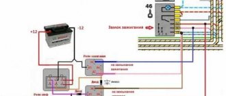
Pinout of the VAZ-2109 ignition switch with unloading relay:
- comes +12V in position I, II, III (parking)
- comes +12V in position I, II, III (parking)
- comes +12V in position III (parking)
- position I, +12V goes out after turning on the ignition (contact 15/2), disappears at start (II);
- position I, +12V goes to the starter (pin 50);
- position I, +12V goes away after turning on the ignition (pin 15), does not disappear when starting II;
- +12V comes from the battery (pin 30);
- comes +12V constantly.
New pinout type
Pinout of the new VAZ-2109 ignition switch:
- comes +12V constantly
- comes +12V constantly
- +12V arrives after turning on the ignition (pin 15), does not disappear when starting II;
- +12V arrives after turning on the ignition (contact 15/2), disappears at start (II);
- position I, +12V goes to the starter (pin 50);
- +12V arrives after turning on the ignition (pin 15), does not disappear when starting II;
- +12V comes from the battery (pin 30);
- comes +12V constantly.
Don't forget the relay
It also happens that the lock is working properly, but the ignition does not turn on, and the starter does not respond at all to turning the key. In this case, you should check the relay. It's called the ignition relay. This device serves to protect the lock contacts from burning when electrical equipment is turned on.
The ignition relay is located in the additional mounting block of the vehicle. To get to it, you will need to remove the plastic panel on the center console to the left of the passenger seat. There are three relays and three fuses. The device we need is usually on the right.
To check whether the relay is working, install one of the neighboring devices in its place, turn on the ignition and try to start the starter. If it starts to spin, replace the faulty device.
Pinout of lock VAZ-2110, VAZ-2111, VAZ-2112
Pinout of the ignition switch VAZ-2110:
- comes +12V for the microphone of the sensor of the inserted key;
- the mass comes when the driver's door is open;
- +12V goes to the starter (pin 50);
- +12V goes out after turning on the ignition (pin 15);
- +12V goes out when the key is inserted to pin 5 of the BSK;
- comes +12V to illuminate the lock cylinder;
- +12V comes from the battery (pin 30);
- not used.
Useful: Lada Vesta VAZ-2180 diagram
What should you not forget when working?
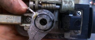
When carrying out repairs, in order to change the contact part, a retaining ring is pryed into the end of the housing with an awl (holds the core of the ignition switch inside a convenient housing), after which the contact part can be removed. The new contact group is installed in such a way that the location of plugs 15 and 30 is where the locking rod is located. In this case, with their wide protrusion, the contacts must fit into an equally wide groove in the housing. All parts are installed on the car in the reverse order corresponding to their removal.
According to the electrical diagram, a new or repaired ignition switch is installed, as well as all wires in accordance with the preliminary marking of the terminals. In order to simplify the connection of wires, their markings are transferred to the new system. Provided all installation and connection rules are followed, the new lock will be able to operate for a long time. In order to guarantee uninterrupted operation and avoid early breakdowns, it is necessary to choose a modern and high-quality model.
Pinout of lock VAZ-2113, VAZ-2114, VAZ-2115
Pinout of the ignition switch VAZ-2113, 2114, 2115:
- comes +12V for the microphone of the sensor of the inserted key;
- the mass comes when the driver's door is open;
- +12V goes to the starter (pin 50);
- +12V goes out after turning on the ignition (pin 15);
- +12V goes out when the key is inserted to pin 5 of the BSK;
- comes +12V to illuminate the lock cylinder;
- +12V comes from the battery (pin 30);
- not used.
Removing the ignition switch, replacing the contact group and immobilizer coil of Lada Granta
Replacing the ignition switch for a VAZ 2106
Tools:
- Ratchet wrench
- 10 mm head
- Medium Phillips screwdriver
- Small flat screwdriver
- Driver for socket attachment
- 8mm wrench attachment
- 24mm wrench attachment
- Chisel and hammer or electric drill
- Long nose pliers
Parts and consumables:
- Sandpaper (fine grit)
- Return spring (if necessary)
- Microswitch (if necessary)
- Contact plate on light guide (if necessary)
- Ignition switch contact group (if necessary)
- Bolt with shear head M6 - 4 pcs.
Notes:
Remove the ignition switch to replace it if its cylinder mechanism fails, to replace the contact group of the ignition switch, and also if it is necessary to replace the immobilizer coil.
Removing the ignition switch
1. Disconnect the wire terminal from the negative terminal of the battery.
2. Remove the steering column covers and left steering column stalk as described in this article.
Note:
For ease of operation, you can remove the steering wheel and the spiral cable drum device.
3. If the ignition switch O-ring was not removed when removing the steering column covers, remove the O-ring from the ignition switch.
4. By pressing the block lock, disconnect the ignition switch contact group wire block from the instrument panel wiring harness.
5. Using a thin screwdriver, pry the edge of the wiring harness block and disconnect the immobilizer coil wiring block from the instrument panel wiring block.
6. The ignition switch is secured with bolts with shear heads; these bolts are tightened until the heads come off. After this, use a chisel and a hammer to tear off the lock fastening bolts, as is clearly demonstrated in the second photo below.
Shear head bolt:
1 – threaded part;
2 – round head;
3 – turnkey shear head.
7. When the caps are already loose enough, you can unscrew them using long-nose pliers.
8. When all the bolts are unscrewed, remove the clamp securing the ignition switch to the shaft, and then the switch itself.
Disassembling and assembling the ignition switch
1. Remove the three screws securing the bracket to the switch body.
2. Remove the bracket from the housing.
3. Remove the ignition switch microswitch drive.
4. Press the plastic latch and remove the microswitch from the bracket.
Note:
To replace the microswitch, you need to unsolder the wires from its contacts.
5. Disconnect the wire block from the backlight lamp socket.
6. Using a screwdriver, unfasten the latch on one side of the ignition switch.
7. Then unfasten the two latches on the other side.
8. Remove the plastic cover from the switch housing.
9. Using a screwdriver, unfasten the two latches on both sides of the cover.
10. Remove the contact group and light guide from the cover.
11. Clean the oxidized or burnt contacts of the plate on the light guide with fine sandpaper.
12. If the contacts are severely damaged, replace the contact plate on the light guide. To do this, turn the contact plate so that its internal protrusions fit into the slots of the light guide and remove the plate along with the return spring. Replace a broken or cracked return spring.
The structure of a car ignition switch
- Locking rod
- Frame
- Roller
- Contact disc
- Contact sleeve
- Block
- Protrusion of the contact part.
The lock mechanism is connected to many wires. They continue from the battery, connecting all the electrical devices of the car into a single chain. When you turn the ignition key, the electrical circuit is closed from the “-” terminal of the battery to the ignition coil. As a result, the current passes through the wires to the ignition switch, through its contacts it is directed to the induction coil, after which it returns back to the “+” terminal. As electricity passes through the coil, it generates high voltage, which it transmits to the spark plug. Therefore, the key closes the contacts of the ignition circuit, thereby starting the car engine.
Basic device
Wiring diagram for the ignition switch on an injection VAZ-2114: detailed pinout of wires
The ignition switch consists of 2 main elements: a contact unit connected to the lock by wiring, and the lock itself, which is called the cylinder. The lock only works with an individual key. Let's describe the device in more detail.
The lock is implemented quite simply: it is a cylindrical design that can both rotate the contact unit and lock the steering wheel. The latter is controlled by a locking rod, which is somewhat reminiscent of a mechanical gearbox lock.
The contact unit is also quite simple: a contact disk
(moving element) and
block with contacts
(fixed element). As soon as the disk begins to rotate, the conductive plates located with it are switched with the contacts of the block. There are 4-6 contacts, but sometimes there are more. By connecting to one contact, you can close one of the electrical circuits of the vehicle.
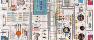
Electrical diagram of VAZ 2104
The electrical equipment of the machine is protected by fuse links installed in the mounting block. The battery charging circuit, ignition and engine start circuits, and the high and low beam relay windings are not protected by fuses. Before replacing a blown fuse link, correct the problem that caused the fuse to blow. When looking for a problem, I advise you to look at the circuits that protect this fuse.
In cars produced before 1988, the fog lights in the rear lights and the fog light warning lamp were protected by fusible insert No. 17 of the mounting block. Since 1988, they have been protected by a separate fuse in the wiring harness near the fog light switch. This insert is designed for current flow up to 8A.
Until 1988, the glove compartment light was protected not by fuse No. 15, but by a second fuse. All fuses and various auxiliary relays were mounted in a separate block in the engine compartment. Also, through the mounting block, the wiring harnesses of the engine compartment are connected to the dashboard harness and to the rear harness.
The mounting blocks are quite easy to disassemble and repair. The old-style block (with finger inserts) consists of two parallel-connected printed circuit boards; the new-style blocks (with knife inserts) have one board. Soldering of wires is allowed in case of bypassing burnt-out tracks on printed circuit boards, but only if this does not require disconnecting the PCB.
What should you not forget when working?
When carrying out repairs, in order to change the contact part, a retaining ring is pryed into the end of the housing with an awl (holds the core of the ignition switch inside a convenient housing), after which the contact part can be removed. The new contact group is installed in such a way that the location of plugs 15 and 30 is where the locking rod is located. In this case, with their wide protrusion, the contacts must fit into an equally wide groove in the housing. All parts are installed on the car in the reverse order corresponding to their removal.
According to the electrical diagram, a new or repaired ignition switch is installed, as well as all wires in accordance with the preliminary marking of the terminals. In order to simplify the connection of wires, their markings are transferred to the new system. Provided all installation and connection rules are followed, the new lock will be able to operate for a long time. In order to guarantee uninterrupted operation and avoid early breakdowns, it is necessary to choose a modern and high-quality model.
Checking the operation of the new lock
The installation work is completed. Now you need to make sure that everything in the car is working properly. First we connect the battery. If the system is operating correctly, when the key is set to position “0”, all systems must be turned off. In position “I”, power is supplied to the engine management system, generator, headlights, warning lamps, washers and wipers, power windows and control devices.
In position “II”, voltage is supplied to the same systems, and in addition, the starter starts. If the lock is operating correctly, the locking rod of the anti-theft mechanism will extend and retract when the key is moved from position “0” (off) to position “I” and back.
As you can see, there is nothing supernatural - you can replace the ignition switch yourself, without turning to a car repair shop for help. The main thing is a little patience and knowledge, and you will master simple car repairs. And the “six” will delight you with its faithful service for a long time. Good luck on the roads!
Installing a new lock
The ignition switch is disconnected. Now we can start connecting the new one.
We connect the contact group of wires
If you are lucky enough to become the owner of a chip that closes the wires, then simply connect it to the new lock.
Connecting the chip
If there is no chip, then we connect each wire separately. We take the terminal block of the new ignition switch in our hands so that the only double terminal located on it is on the right and in a vertical position. The top compartment of the double terminal corresponds to the double black wire.
Wiring pinout by color
Next we move counterclockwise. The next one to connect is the pink wire, followed by the double blue, then the brown, and the last one is red. In addition, you can figure out the location of the wires on the terminal block using the digital marks that mark the block itself. There is a designation near each terminal; let’s look at how the terminals correspond to the colors of the wires:
- 1NT – black double wire
- 30 – pink wire
- 15 – double blue wire
- 30/1 – brown wire
- 50 – red wire.
The lower part of the double terminal remains empty - as it should be. Contacts are connected.
Back of the castle
We install the lock in place and finish the job.
Now it's time to lock the new lock in its original position - to the left of the steering wheel.
So, insert the key into the lock and fix it in position “0”. Then we take the lock and insert it into its original position, “sinking” the side lock with your fingers. Now the lock is in place, so we can tighten the mounting screws and install the decorative protective cover.
VAZ 2104 car platform
At first, the VAZ 2102, which was an “extended” version of the classic “penny”, was assembled as a universal model with increased capacity in factory buildings. However, having identified a number of design flaws, the engineers decided to use a different platform for the station wagon.
At its core, the VAZ 2104:
- It was an extended modification of the VAZ 2105;
- Most of the parts were unified with the entire model range of the Zhiguli family;
- The rear of the car received a full-size door equipped with heated glass and a windshield wiper;
- An additional center console with function keys has appeared in the cabin.
For reference: The factory instructions offered for the new car did not always reflect the changes made during the production and modernization of the VAZ 2104.