Types of window lifters
Automobile manufacturers produce cars of different configurations. The cheapest ones have manual windows. They create fewer electrical problems, but the inconvenience of using them is that while in the driver's seat, it is impossible to open the window on the passenger side without being distracted from driving.
Manual window lifters, which are installed on the conveyor, have slight differences from electric ones. The mechanism itself that lifts the glass is exactly the same.
The difference is that the manual version has a gearbox that transmits the rotation of the window handle to the window lifting device, while in the electric version this function is performed by an electric motor. On the door trim, in place of the hole for the manual drive, there is a plug. In addition, the electrical wiring has an additional connection diagram for VAZ-2114 window regulators.
Manual window lifters
The glass lifting devices on the front and rear doors are similar. The difference is only in the sizes and proportions of the parts, while the operating principle is the same.
The main part is the guide in which the bracket that fixes the glass moves. The guide has fastening bolts at the top and bottom. With their help, it is installed in its position on the door. On the upper and lower edges of the guide there are rollers rigidly fixed along which the cables run that drive the glass mounting bracket.
Another part of the window regulator is the mechanism that operates the cable. It consists of a roller and a gearbox, which is rotated either by a handle or by an electric motor (if the VAZ-2114 window regulator has an electrical circuit).
To ensure that the cables are constantly lubricated and not subject to contamination, they are placed in rigid steel jackets that connect a system of three rollers together.
There are two threaded holes on the top of the glass bracket. The bolts that secure the glass holder are screwed into them.
Lever window lift
One type of window lifting mechanism for the VAZ-2114, which, unfortunately, does not come from the factory, is a lever window lifter. These products are manufactured by Ningbo Stone.
These devices have proven themselves to be reliable and unpretentious mechanisms. Unlike cable window lifts, they have a greater lifting force. Glass frozen in winter is not a problem for them. They can handle them easily, while cable lifts experience significant stress on both the mechanism and the electrics.
One small disadvantage of the lever mechanism is that the speed of raising the glass is not the same. The higher the glass, the smaller it is. This is due to the geometry of the lifting mechanism. A good example would be scissors. If you take them by the rings and move the ends apart as much as possible, and then bring the rings closer to each other, it becomes clear that the height of the cutting ends changes faster when the rings are moved apart as much as possible. Conversely, the rate of ascent decreases as the rings move closer together.
It is this circumstance that allows this mechanism to create significant force. As we know from physics lessons, when you lose in distance traveled, you gain in strength. The same thing happens here: at the top of the range of motion, the distance traveled decreases and the lifting force increases.
The mechanism is driven by an electric motor and is connected as standard to the VAZ-2114 window lift circuit.
see also
Comments 8
This diagram is complete crap, tested on my VAZ 2115, it works fine, only the right driver's door window regulator doesn't really work, then it gets jammed, then the power disappears; it's easier for each window regulator to have its own power supply and its own button
Thank you very much for your very useful and insightful comment. The presented factory diagram clearly shows that each window regulator receives its power through its own button from the mounting block. The scheme is quite simple. So it’s even interesting what is to blame for the circuit, that “the right one doesn’t really work, then it jams or the power disappears.” And how “each window regulator has its own power supply and its own button” will solve your problem. Maybe we should look for the reason in the poor contact of the connectors and the closing mechanism of the window regulator (by the way, this is not uncommon, the mechanism with a cable is often covered)?
tell me x1 is + with ChY? There is NO photo of the block in the new mounting block (2114) from which to take + to the ESP, otherwise I can’t find anything (
This scheme turns out to be 3 buttons! But the window regulators come with wiring for 2 buttons. Separately, you can find the wiring for exactly 3 buttons, otherwise I just have a problem with them now... At first the problem I had was that the left glass closes and opens well (quickly), but the right one does not work well. I still don’t understand why (Then I decided that the place where they are installed is not suitable (where there should be heated seats, in the middle), I decided to move them to the doors, but with 3 buttons. The whole execution turned out perfect, but when all the buttons on the right door are connected, it doesn’t work! He said that because of the wiring, supposedly it is designed for 2 and not 3 buttons. It’s hot outside, below 30, and I’m driving around with a fan). Have you or someone you know encountered this?!
Has anyone tried connecting according to this diagram?, the second button on the top in the connection is questionable!
Diagram from the ABC book. To be honest, I didn’t look closely at first (I have standard ones), but now I see for myself that the numbering of contacts on the “2” button, which is at the top, frankly speaking, is “left”. Apparently, the “inside” of the button should be mirrored there. If you “unfold” it, then everything falls into place. In general, everything is as always. Even a diagram from a primer needs to be modified with a file. “Reflected”, I post it.
Read also: Motor oil transportation hazard class
Yesterday I installed the power windows using this diagram, everything works, the diagram has been checked, everything works))))
VAZ-2114 is a car in which a window regulator malfunction is a common occurrence. This is one of those troubles that does not interfere with driving, but pretty much spoils the nervous system of a car enthusiast. The inability to ventilate the air in the cabin or reduce the temperature in the summer often reduces the composure that is so necessary for a person behind the wheel.
Rack and pinion window lift
Another good option for replacing standard mechanisms is rack and pinion windows. They are produced and have proven themselves well. These devices are characterized by high lifting and lowering speeds. Just as in the case of lever mechanisms, they have more force than standard ones. Despite the more modest dimensions of the electric motor, which is connected by standard connectors of the VAZ-2114 power window connection diagram.
The secret to the reliability of the device is the simple kinematic diagram of the transformation of the rotation of the electric motor shaft into the translational movement of the glass mounting bracket. There is a gear on the motor shaft that meshes with the teeth of the rack. This allowed additional parts to be kept to a minimum and simplified the design. And in combination with high-quality manufacturing materials, it ensured reliable operation.
Window lifters on the VAZ-2107: detailed diagram
The market for auto products for VAZs of the old mechanical type contains sets of electric windows from numerous manufacturers. The most popular are “GRANAT” and rack and pinion “FORWARD”. The lift rack is a housing with a toothed chain drive that allows you to move the glass. An electric motor is based on the rack, which starts the working mechanism, which is stationary.
To connect the electric windows, the power supply is used. The VAZ-2107 has a cigarette lighter for this purpose, otherwise the electrical wiring is carried out from the battery.
Power window
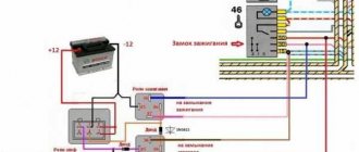
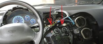
The vehicle configuration with electric windows contains additional bundles of wires that make up the VAZ-2114 window lift circuit. In addition, there is a control button on the front passenger door trim. On the driver's door there is a block of buttons that control all windows that have an electrical connection for the VAZ-2114 power windows.
The scheme has the following elements:
- Mounting block.
- Front passenger door ESP button.
- Front passenger door lift motor.
- Driver's door ESP electric motor.
- Driver's door switch button.
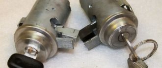
- Egnition lock.
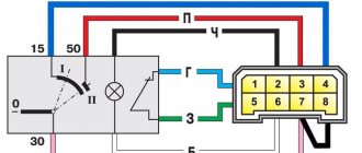
The letter “A” in the diagram indicates the wires going to the power supply of the circuit, and the letter “B” indicates the wires going to the side lights.
How to connect a button?
The driver and passenger door buttons are connected to each other, as well as to the ESP motor and power cable. Correct pinout of the power window button:
- Pin 1 on the driver's door is connected to pin 6 on the passenger side. Contact 1 on the passenger door is connected to the negative terminal of the ESP motor.
- Pin 2 on both buttons is connected to power.
- Pin 3 is the ground on the driver's side and the positive wire on the passenger's side.
- Contact 4 in both cases goes to the headlight switch.
- Contact 5 is ground in all cases.
- The positive wire of the ESP motor corresponds to pin 7 of the passenger door button.
Pinout of the window lifter button on the VAZ 2114
When you need to install ESP (electric windows) yourself, then, as always, on the Internet it is difficult to find correct and understandable diagrams for everyone. Having experience in radio electronics, I am laying out for everyone the correct and understandable diagrams for connecting an ESP, an intelligent glass closer Pandora DWM-210 (but it is better to install a Sheriff PWM-200), as well as simple closers only for raising the glass, installed in the wire gap on the positive side of the motor.
The process of installing the ESP is described in detail by me here: www.drive2.ru/l/4651635/
We take ESP power buttons (NOT low-current trigger (multiplex) from Itelm), namely power ones: a block from Granta, and a new model button from Kalina (it’s the power one), since they are the cutest in appearance. These are, of course, not dual-mode imported buttons, but they will work just as well with an intelligent door closer. We also install the Sheriff PWM-200 type door closer itself.
Power buttons are easy to identify by their contacts - they have thick and flat blades, while trigger buttons have thin pins like needles! We use thick power wires (shown in bold in the diagrams) >= 1 mm2, while control wires can be used thin = 0.5 mm2.
Exception! If the buttons are not on the door, but on the center console, and thick wires >= 1.5 mm2 are stretched from them to each door, then you can do without a relay, since there is no duplicate button here, and each one is on its own door, so the drawdowns are minimal. Then you don't have to read further. Or install two 5-pin relays from each button in each door as close as possible to the ESP motor, while stretching thick wires to plus and minus, and thin control wires from the buttons.
You will need a soldering iron and the following parts:
Power window switch VAZ-2190 AVAR block Article: 357.3769 2190-3709810 — 450 rub. or Control unit for VAZ-2190 window lifters AVAR 3573769 Article: 357.3769 — 450 rub. Power window switch VAZ-1118 N/O AVAR Article: 921.3709 1118-3709613-10 — 230 rub. Power window control key block with 7 wires AENK Article: 2106-3724568SB, 2106-3724568SB7 — 40 rub.
The following relays are also needed:
Electromagnetic relay 12V 5 contacts with bracket AVAR - 90 rub. Connector block with 5 AENK wires - 40 rubles. Terminal (female) 6.3mm tinned with AED clamp - 10 rub.
Plus +12V must be taken from the fuse block, and not from the ignition, otherwise the automatic window closer will not work when arming. It is better to take the weight from the bolt behind the mounting block, and not in the door, since the contact in the door may not be very good. Although the door contact is also good if the car is not old. Take tinned terminals.
Connection diagram for power window lifter button "AVAR"
Contacts 1-6 and 7-3 are normally closed (NC). 1-2, 7-2 - normally open (NO), respectively. That is, 2 pairs of switching contacts When you press the up button, contacts 1-6 open and 1-2 close (window rises). When you press the down button, contacts 7-3 open and 7-2 closes (window down).
Diagrams for connecting the backup button on the driver's door to the main button on the passenger door
When installing two buttons on one window regulator, they are usually installed in series (or in parallel, but then they must be decoupled via a relay).
The main button is the button that controls the power window of the door on which it is installed. The duplicate button is the driver's button, which additionally controls another window regulator from the driver's seat.
Daisy chain connection (for low current trigger buttons)
We connect the output of additional button 1 in the driver's door to input 6, and output 7 to input 3 of the main button on the passenger door. We cut the wires in the block connecting contacts 5-6 and 6-3. The minus of contact 5 now goes only to the backlight, and contacts 6 and 3 now take the output from additional buttons 1 and 7 of the driver's door and in a normally open state the minus comes from them. Attention! Connecting the buttons in parallel will result in a short circuit when raising and lowering, so only in series as in the diagram! Power wires are highlighted in bold.
Since the circuit is serial, there are large voltage drops along long wires and the passenger window moves very slowly! Therefore, when using a duplicate button, be sure to use two 5-contact relays, in which the output 30th contact, without supplying voltage to the winding contacts (85 and 86), is constantly shorted to contact 88 (87a in imported relays), which gives us the necessary negative contact when the relay is de-energized (works as a switch). The backup button (on the driver's door) does not need relays, since it essentially controls its own relay through the passenger button. The relay must be located as close as possible to the passenger's ESP electric motor (if there is no closer) or before the entrance to the closer (after the closer it is impossible, since the electromagnetic noise detector will not work and will turn until it burns out!), that is, as close as possible to the consumer ! If voltage is applied to the winding at pin 85, then output pin 30 is disconnected from pin 88 and connected to pin 87. Pin 86 of the winding is connected to minus (ground). Use only these 5-pin power relays!
Use only such relays!
The power contacts are always marked as 30 (output), 87 (input when control is applied to the winding) and 88 (normally closed input). The wires to them must be used as thick and as short as possible.
Relay 90.3747 - in a plastic case with a mounting flange; Relay 113.3747 or 75.3777 - in a metal case with a mounting flange; When using low-current multiplex (trigger) buttons, connect all ESP motors only through a relay! When using a conventional door closer, relays are also needed, since they are not in the long-press closer block and all the current flows through the buttons and wires from them. If the closer has its own relays and they are used for both short and long presses, then separate relays are not needed.
Parallel connection (only for power buttons)
Since with a serial connection you still can’t do without a relay, you can make a button duplication circuit in parallel by decoupling the main button from the backup button through two 5-contact relays: the wires from the main button next to the driver’s ESP motor go directly to the 88th contact of the relay and from pin 30 directly to the engine, and long wires from the backup button go to pin 85 of the relay winding, and the relay feeds a powerful plus to the passenger’s ESP engine. With a parallel one, there is no need for a relay on the main (passenger) button (the wires are short here), and we thereby eliminate unnecessary clicking of the relay when the main button on the passenger door is pressed. But still, even for power buttons, it is better to use a serial connection so that the contacts in the buttons do not burn. Moreover, for non-power low-current (trigger) buttons, in this case you will definitely have to use 2 more extra relays to relieve the load on the passenger button (therefore, a serial connection is always used for trigger buttons).
Connection diagram for multiplex (low-current) ESP button
ESP connection diagram when the multiplex button closes the contacts to ground
Dimensions of the installation location for the ESP “AVAR” buttons
Terminals of the power window power button block for the diagram
Glass closer Pandora DWM-210
What it gives: - full glass travel in one short press (“one touch”) - BUT DOES NOT WORK ON 2 GLASSES AT THE SAME TIME (since the module has only one sensor for electromagnetic noise of the motor, current and time); — stopping the glass in any position by pressing again in any direction; — automatic stop of the glass when it encounters an obstacle in the window opening; — automatic shutdown of ESP motors when current is exceeded; — automatic closing of windows when arming the car; — automatic opening of the windows when disarming to the previous position before arming, if the parking lasted no more than 20 minutes. (The rev counter works rather conditionally and may leave the windows closed or not closed enough). The closer is installed in the driver's door.
ATTENTION! When you hold the button, the closer does not use its relays, which take the plus (via a 20A fuse) and minus from the closer, but sends all the current directly from the button to the motor, so you need to install a relay after leaving the button with long wires! Apparently this was done so that if the door closer fails, you can always close the window by simply holding the button. When you briefly press the button, the closer with its relays is activated and closes the glass. Place the relay only at the entrance to the closer from the output after the backup button! If this is not done, then due to subsidence along the long wires of the sequential connection of the buttons, the passenger window will barely move. The output of the closer must be connected directly to the motor without a relay, otherwise the detection of electromagnetic noise from the motor will not work and the closer will not work! At the output of the driver's power button, relays are not needed, since all the power wires there are short. It is ideal to install 2 door closers on each door, as is standard on foreign cars - then the AUTO mode will be on 2 doors at once in parallel, and not alternately. In addition, you will not need to pull 2 extra thick wires to the motor from the driver's door to the passenger's door. If I had known right away that the Pandora DWM-210 is such a Ketai crap without its own relays in the power part of the door closer, I would have purchased and installed a Sheriff PWM-200 door closer, in which the power part is clearly separated from the control part and, moreover, you can close two windows at the same time in one touch! So it's definitely better!
Connection diagram for the passenger door button in series through a duplicate button on the driver's door. Contacts 1-6 and 7-3 are always normally closed. When you press the up button, contacts 1-6 open and 1-2 close (window rises). When you press the down button, contacts 7-3 open and 7-2 closes (window down). The 30th contact of a 5-pin relay, without supplying voltage to the winding contacts, is constantly shorted to contact 88, which gives us the necessary negative contact (works like a switch). If voltage is applied to the winding, then contact 30 is disconnected from contact 88 and connected to contact 87. Contact 86 of the winding is connected to ground.
The power windows are turned on by the module sequentially after a trigger pulse is given: first the driver's door, then the passenger door, and the next channel is turned on after the previous one has been completed. If the glass is already closed, the module will immediately switch to the next channel. Closing control is carried out by electromagnetic noise from the motor.
When the power is turned on, the closer module needs to be calibrated based on the protection current. You need to press SHORTLY to lower each glass all the way, then raise it in the same way. At the same time, the closer remembers the characteristics of the engine. The control signal for closing and opening is NEGATIVE ONLY. Control can be done from the central locking or from an additional alarm channel. It is necessary to connect the control output of the security system to the “White/Red” (windows up) and “White” (windows down) terminals of the module, respectively. The duration of the trigger pulse must be at least 500ms. (0.5 sec.). Attention: in older releases the wires of the buttons and motors were swapped - for such blocks we swap the wires numbered: 9<->2, 16<->20, 15<->10, 14<->19, 13<-> 18. On the latest Pandora (November 2011 and newer) the circuit is correct, so there is no need to swap the wires from the buttons and motors!
Closers for breaking wires for lifting ESP type Convoy CL-200 Addition dated 10/05/2014 at the request of SIBUR95
There are closers like Convoy CL-200, which are connected to the break in the lifting wire that goes to the ESP motor. There are 2 wires coming from the closer (input and output) and they are constantly closed in it. When the closer is turned on, they break and a plus + appears on the output. On GREEN, when the door closer is operating (arming), a plus appears and it goes to the engine, and a minus goes from the button (or from the relay from contact 88 to 30) to the engine. When the closer does not work, it simply passes current from BLUE to GREEN by closing its relay and that’s it.
Here the circuit differs only in that the minus of the motor is connected directly to the button (or to the relay, if the button is duplicated), and the plus also passes through the closer, and the relay is only at the INPUT of the closer, thereby not interfering with the detection of engine noise.
There is only one output wire from the closer to the engine - this is GREEN - and you cannot install a relay here since you need to determine the engine noise. Here there are already enough relays at the input to the closer on BLUE, since it will immediately go to the output on GREEN and there will be no drawdowns. But the second wire to the engine goes past the closer. There will be no losses on the closer itself! There will be small losses from the GREEN wire, which goes from the closer to the engine, since it is long and runs under the dashboard from the driver's door to the passenger's door. Important! The second relay, which goes past the closer (to the minus of the engine), needs to be installed precisely near the passenger engine, thus this second wire will be the control wire on the relay, which will switch the plus and minus right here, near the engine, eliminating drawdowns.
You can also make a button duplication circuit not in series, but in parallel on two 5-pin relays. The advantage is that a series circuit is eliminated; the relay will not click again from the main button, which is closer to the engine (with short wires), but only from the backup one. The downside is that for non-power (trigger) buttons in this case you will have to use 2 extra relays (relays 3 and 4 in the diagram).
Scheme for any number of duplicate buttons and number of doors
Excellent low-current control circuit and any number of buttons from McSystem
You can put as many buttons in parallel as you like and simultaneously press them in different directions - a short circuit is impossible from the circuit design! In a situation where we press the up button on the main button, and the down button on the backup button, it will simply stop, since both power lines will have the same potential.
The only difference between the closer is the presence of an MK between the buttons and power relays. The advantage of the circuit is that the power switching is in one place, there are no losses in the harnesses and on the buttons, there is a minimum of “pulling” of wires - 2 in total per channel + ground. In good quality, full-featured closers, the power part and control lines are implemented in the same way + the functions of “auto-detection” of active control levels are also added.
If a door closer of the PWM-200 on Sheriff type with low-current control is installed, then there is no point in these relays, since they are already mounted in the door closer. This circuit with a relay is for understanding the essence of reverse control and duplicating buttons in parallel. Power outputs both in the central locking system and in the door closers are implemented in exactly this way.
It is also advisable to connect non-polar electrolytic capacitors of 22 uF 25V to the contacts of the ESP motors in order to smooth out the range of current ripples in the power channel of the closer so that it works correctly even when the motors are worn out and does not suddenly stop the glass when opening and closing.
The usual scheme of duplicate buttons for 4 doors
Duplicate buttons must also be supplemented with two 5-pin relays (they are not shown in the diagram).
This is what the power button contacts look like - thick rectangular blades
Lada Granta ESP diagram
How to disassemble the door of a VAZ-2114?
To get to the window lifting mechanism, you need to remove the door trim. In addition, if you plan to replace it with an electric lift, then you need to dismantle the opening limiter, since a bundle of wires will need to be inserted into the door. To remove the casing:
- Unscrew the three screws from below that hold the plastic pocket of the trim.
- Remove the two bolts holding the inner handle. To gain access to the bolts, you need to remove the round plugs using a thin flat-head screwdriver.
- Remove the plastic trim from the door lock handle. To do this, you need to pry it up with a screwdriver and, moving it a little to the side, pull it out of its recess.
- Unscrew the lock button.
- Remove the trim. This is done as follows. A flat pry bar or a powerful screwdriver is inserted into the gap between the trim and the door frame. It should fit between the door clip and the door frame. Then you need to squeeze out the clip, not the casing. Otherwise, the clip fastening can be broken, and during subsequent installation the casing will not sit tightly in place. There are 8 clips installed around the entire perimeter of the door. They need to be pulled out one by one.
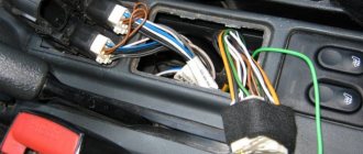
After releasing the door trim, there is no need to rush to remove it. If it is a door with an electric drive, then it is connected by a bundle of wires going to the window lift button, the pinout of which consists of seven contacts covered by a plastic connector. To disconnect it, you need to press the latch with a small screwdriver and pull out the part into which the wires go.
Installation of lifting devices on a VAZ
The sequence of the procedure will be as follows:
- We temporarily remove the glass seal from inside the door;
- we take out the glass and dismantle the lift mount;
- We install devices powered by electric drive;
- connect the minus terminal to the battery and check the device;
- We install glass and trim the door.
Electric windows, compared to mechanical ones, do not contain gear-type gearboxes, which are more common, but a drum. A DC motor shaft is inserted into the center of the drum. The motor is a gear motor component, influencing the speed, raising and lowering of the windows.
Installation is not difficult. First, the battery is disconnected. Using a curved screwdriver, you unscrew 3 screws, unfasten the door trim latch and dismantle the pocket. Use a thin screwdriver to pry off the lift lock handle. The tip is located in the recess located between the socket and the fixing part.
After removing the handle, the door handle is removed, opening the car door. The handle cover is pryed off and then removed. Using a screwdriver, unscrew a pair of screws to secure them, which are covered with a cover plate. It doesn't take much effort to remove the handle. You will need to use a screwdriver to remove the power window button that blocks the door.
After removing 6 pistons, the trim of the adjusting mirror in the car is removed. The door trim can be easily removed. Using a 10mm wrench, unscrew a couple of bolts using the auto glass clip. Then you need to sequentially unscrew a couple of nuts securing the lifting mechanism, securing the nuts at the top and bottom, and then 3 nuts securing the lifting mechanism.
Upon completion of the stage, the pin should be removed in the direction of the lifting device from below from the panel on the door. In order to simplify the operation, you need to bend the guide pin located on top using a screwdriver. The lifting mechanism can be easily removed through the frame opening in the door.
Replacing the window regulator
If the VAZ-2114 window regulator does not work, it can be replaced with a new one. To do this you need to do the following:
- Using a 10 mm wrench, unscrew the three nuts that hold the glass guide.
- Using a size 8 wrench, unscrew the three nuts that secure the electric motor or manual drive gearbox.
- Disconnect the glass mounting bracket from the glass holder. To do this, you need to unscrew the two 8mm bolts on the bracket.
After this, you can pull the window regulator out of the door. The glass must remain raised. Otherwise it will be impossible to remove the mechanism.
The new lift is installed in the reverse order. However, there is no need to rush to tighten the glass mounting bracket. First you need to make sure that the glass is in the correct position in the guides and moves clearly in them.
Installation and connection diagram for VAZ 2109 window regulators: step-by-step instructions with photos
- Before starting work, you must turn off the power supply to the vehicle's on-board network from the battery. Or we separately turn off the power circuits for the cigarette lighter and the backlight of the instrument panel and buttons. because The power supply wiring for the power windows will be connected to these circuits in the future.
- Remove the door trim. It can be removed quite easily, but it is better to stock up on mounting pins.
- First of all, we dismantle the mechanism of the standard manual window lifter, fixing the glass (for example, using office tape) in a position that provides access to the place where it is attached to the lifting mechanism.
- Unscrew the bolts securing the door glass to the standard window lifter mechanism.
- We dismantle the guide of the standard window lifter mechanism (trapezium). Unscrew the bottom nut:
- Two nuts in the middle:
- Top nut:
- The guide is free, now all that remains is to unscrew the three nuts securing our window lifter in the area of the rotation handle.
- We take out the entire door window lifter mechanism. To do this, we bring the lower pin of the guide into the hole in the door (see photo).
- By pressing with a screwdriver, we remove the upper fastening of the guide.
- Done, the window lift mechanism is disconnected. We take it out of the door cavity.
- That's it, the standard mechanism has been dismantled, let's start installing a new one. The new mechanism is attached using standard fasteners; you don’t have to drill anything new. We place the window lifter mechanism into the inner cavity of the door through the largest technological hole in an “assembled” form (otherwise it won’t fit), as if in the “open” position of the glass.
- We fasten the mechanism inside the door using two studs, which we insert into two holes that previously held the middle part of the guide of the standard VAZ 2109 window lifter. We combine them and screw on the nuts.
- The next task is to combine the mounts on the window lift linkage system with the mount on the glass. This can be done by supplying power to the power window motor contacts from an external power source, for example, any working car battery.
- When the lift mechanism is combined with the strip on the glass, we connect them using the bolts from the kit.
- It is advisable to lubricate the rubbing parts thoroughly.
- The mechanical part is complete, let's move on to the electrical part.
- We estimate the route for wiring from the door from the electric motor of the window lift drive to the installation location of the buttons - activators. The standard place for buttons in the high panel of the VAZ 2109 is two plugs to the right of the cigarette lighter, and we install them there. The hardest part is running the wiring from the door into the rack and then out of the rack under the dash. For this purpose, there are technological holes in the rack. You may need to use a special probe. The wiring is done with a wire with a cross-section of at least 1 mm. sq. We lay the wires in such a way that they do not touch any moving parts of the door or the ESP mechanism itself. We will take power for the electric windows from the cigarette lighter. Electrical connections are made according to the following diagram:
When the circuit is assembled, it is necessary to connect the battery power and check the correct operation of our system. We turn on the side lights and check the correct operation of the backlight of the ESP activator keys. If the backlight does not work, swap the sockets on the contacts of the keys, indicated in the diagram as 3 and 6. You can install the window lifters in the standard way, here are two diagrams:
Connection diagram for electric windows on a VAZ 2109 with mounting block 17.3722 (before 1998)
Connection diagram for electric windows on a VAZ 2109 with mounting block 2114-3722010-60, 2114-3722010-10 and 2114-3722010-18 (new model)
This is interesting: Stand for testing generators and starters
You can read more about the types of mounting blocks for front-wheel drive VAZs here.
- We check the functionality of the window regulators. The glass should move smoothly, without jamming or jerking, and should not come out of the guides. To facilitate the movement of glass in the seal, it can be treated with silicone grease.
- All that remains is to reinstall the door trim.
- That's it, the installation of the window lifters is complete, let's enjoy the completed modification!
How to install and connect electric window lifts “Granat”: video experience
Installing central locking
Installing power steering, part 2: Rack
Installing an electronic tachometer
A more competent solution would be to take power from the mounting block. Added diagrams.
I wanted to see a more experienced solution for supplying power to the beet lifters; the mounting block has a relay on them.
The smartest thing, in my opinion, would be to take power for the ESP from the battery! Practice shows that as long as the current passes through the terminals of the mounting block and its fuses, it is lost! And if you take the main plus from the battery, then the ESP flies like crazy
Reasons for poor performance
There are not so many reasons why the VAZ-2114 window regulator does not work well. Conventionally, they can be divided into mechanical and electrical. Let's consider the main ones:
- Glass distortion. Often the reason for poor performance is not the window lifting mechanism itself, but a violation of the position of the glass relative to its guides. This can happen either due to the bracket fastening being unscrewed, or the damp rubber fixing the glass in the holder has ceased to perform its functions. This option occurs much less frequently.
- Contamination of the guide rubbers. The glass moves inside the grooves formed by the rubber bands. These grooves tend to become clogged with dirt. It, like an abrasive, increases the friction force, which creates resistance to glass movement.
- The window lift mechanism is dirty. During operation, drivers do not realize that maintenance is also necessary inside the doors. This is especially true for the cable mechanism. Over the years, not only does contamination occur, but also the lubricant of the mechanism and cables dry out, which increases the friction force. The front left window regulator fails faster due to more frequent use.
- The next reason is wear of the plastic teeth of the mechanism drive. In this case, when you press the control button, you can hear the electric motor running, but the glass does not move.
- Broken cables. This occurs due to attempts to open frozen windows. With repeated loads exceeding the rated ones, the cables begin to delaminate and gradually fail.
Electrical reasons can be reduced to either a short circuit or loss of contact in the VAZ-2114 power window circuit.
Replacement cost
Replacing VAZ-2114 window regulators is cheaper than installing electric mechanisms to replace manual ones. If, in order to simply change the window regulator, you need to disassemble the door trim, dismantle the old mechanism and install a new one, then to install an electric version instead of a manual one, you need to partially disassemble the instrument panel, select a power source and run the wiring from it inside the door. This work requires the intervention of an electrician. Because power cannot be taken from anywhere: the source must match the power of the electric drive, and in the event of a short circuit, the fuses must protect the main wiring of the car. In addition, the power windows must operate when the ignition switch is on.
To summarize, we can say that in the first case, the qualifications of the work are minimal, and it can be done by yourself, without having specific knowledge, while working with an electrician requires a specialist who needs to be paid.
The price of a VAZ-2114 window lifter ranges from 2.5 thousand to 3.5 thousand rubles, depending on the design and manufacturer. But as was said earlier: the lever and rack and pinion options are preferable. If you buy a device for only one side, then the left front window regulator will be more expensive, since it is more in demand.
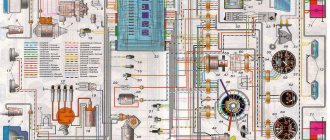
Wiring diagram for a VAZ 2114 car
Electrical wiring components
A single-wire circuit (used for all electrical wiring) has negative terminals of the consumer and the source, which are closed on the car body. The VAZ 2114 body is the second connector.
Complete circuit with electronics in VAZ 2114
Electrical wiring includes the following components:
- Block headlight.
- Anti-fog headlight.
- Temperature indicator.
- Mounting block housing.
- Electric fan motor in the engine cooling system.
- A block connected to the ignition system wiring group.
- Engine compartment light switch.
- Rear wiper motor connector plug.
- Devices.
- Car signal connection block.
- Electric motor for windshield wipers.
- Loudspeaker signaling device (SSU) housing.
- An indicator showing the volume of water in the glass washer.
- Front brake pad mode indicator.
- Oil quantity indicator.
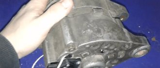
- Generator and starter housing.
- Reversing headlight switching device.
- Lubricant pressure warning light indicator.
- Windshield wiper gear motor housing.
- Light housing under the hood.
- Engine coolant temperature indicator. 2x h16
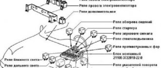
Circuit breakers
In fact, the VAZ 2114 wiring is always connected to fuses. Such fuses do not protect only the circuit of the generator and charging device, the mechanism for switching on the power unit of the machine, as well as the winding of the backlight cut-off relay.
Before replacing a failed electrical circuit fuse, you need to find out exactly the reasons for the wiring overload, as well as its elimination. Finding the cause will be much easier if you first read the following materials. Below is a list of fuses and their purposes.
The data (the name of the fuse and the electrical circuit protected by it) shows a complete list of all possible wiring fuses. For each car, their number may differ.
- F1. Wiring diagram for the rear fog lights, electric motors for the headlight wipers, housing for the control lamp and its shutdown, electric motor for the headlight cleaner.
- F2. Turn signals and turn signal relays, hazard warning lights, hazard lights.
- F3. The wiring of the lamp illuminating the interior is customized depending on the personal preferences of the car owner, the ignition switch light, the car trunk light, the engine functionality check indicator, the on-board computer, the brake light indicator, and the clock.
- F4. A plug for connecting a portable lamp, a plug that connects the heating of the stern and rear windows.
- F5. Connection diagram for SGU, radiator propeller electric motor, VIP signal relay.
- F6. Power window relay, power window connection circuit.
Fuse box in VAZ 2114 - F7. Wiring of the electric motor of the VAZ 2114 stove, electric motors for the headlight wipers and windshield washer, cigarette lighter circuit that illuminates the glove compartment, light bulb, relay for connecting the aft glazing heater winding.
- F8. Wiring diagram for the right fog lamp.
- F9. Left fog lamp diagram.
- F10. Electrical wiring for the side lights on the left side, an indicator that shows whether the side lights are on, a circuit for the engine compartment lamp, illumination of license plates, heating system levers and ashtrays, a cigarette lighter, a circuit for illuminating the switches.
- F11. Side lights located on the left side.
- F12. Right low beam design.
- F13. Left low beam design.
- F14. High beam device and left bulb. It is also an indicator for switching to high beam.
- F15. Right high beam design.
- F16. Wiring of turn signals, hazard light relay, relay responsible for the state of the lamps in the headlights, rear traffic indicator, lights signaling the following: low oil and brake fluid levels, whether the parking brake is on, low battery charge. Also a clock, an on-board computer and a generator excitation winding circuit during the start of the power unit of a VAZ 2114 car.
In addition to all the fuses listed above, which are located in the mounting block, there are 3 fuses. These fuses are located under the magazine shelf. The controller and relay circuit are also located here, with the help of which the VAZ 2114 power unit is controlled.