Schematic electrical diagrams, connecting devices and pinouts of connectors
The ignition switch in cars of the VAZ family fails from time to time due to weakening of the contact posts or burning of the contacts inside it. It also happens that the cams of a plastic roller are produced. You can disassemble the lock and clean it, but it’s better to just replace it with a new one, considering that it costs pennies compared to imported locks.
But if connecting the wires together did not result in the starter operating (or it did not turn on the first time), check the solenoid relay on the starter. The contact spots on it may also burn out, which will prevent the circuit from closing normally. Alternatively, you can use a screwdriver to short-circuit the two large terminals on the solenoid relay (before doing this, put the car in neutral and use the handbrake). When closed, the starter should begin to spin vigorously. If this happens, remove and change the solenoid relay. If the starter rotates “sluggishly” when it closes, you will have to remove it and check the condition of the brushes.
All operations are performed with your own hands, without the help of car service specialists. Moreover, the price of an ignition switch on a VAZ2106 is up to 100 rubles. To replace it, you will need to know the pinout of the wires coming from it, for which the editors of the site 2 Schemes.ru have prepared a large reference material.
The ignition switch is designed not only to start the engine - it performs several functions at once:
- supplies voltage to the vehicle’s on-board network, closing the circuits of the ignition system, lighting, sound alarm, additional devices and instruments;
- at the driver’s command, turns on the starter to start the power plant and turns it off;
- turns off the power to the on-board circuit, preserving the battery charge;
- protects the car from theft by fixing the steering shaft.
Pinout of the ignition switch VAZ-2101 - VAZ-2107
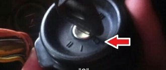
The ignition switch on these cars is located to the left of the steering column. It is fixed directly to it using two fixing bolts. The entire mechanism of the device, except for the upper part in which the keyhole is located, is hidden by a plastic casing.
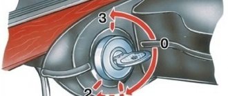
On the visible part of the ignition switch housing, special marks are applied in a certain order, allowing inexperienced drivers to navigate the lock activation mode when the key is in the hole:
- “ ” – a mark indicating that all systems, devices and instruments that are turned on using the lock are turned off (this does not include the cigarette lighter, interior lighting, brake light, and in some cases the radio);
- “ I ” is a mark informing that the vehicle’s on-board network is powered from the battery. In this position, the key is fixed independently, and electricity is supplied to the ignition system, to the electric motors of the heater and windshield washer, instrumentation, headlights and light signaling;
- “ II ” – engine start mark. It indicates that voltage is applied to the starter. The key does not lock in this position. If you release it, it will return to the "I" position. This is done so as not to subject the starter to unnecessary loads;
- “ III ” – parking mark. If you remove the key from the ignition in this position, the steering column will be locked with a latch. It can only be unlocked by inserting the key back and turning it to position “0” or “I”.
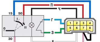
The ignition switch has five contacts and, accordingly, five terminals, which are responsible for supplying voltage to the desired unit. All of them are numbered for convenience. Each pin corresponds to a wire of a certain color:
- “50” – output responsible for supplying current to the starter (red or purple wire);
- “15” – terminal through which voltage is supplied to the ignition system, to the electric motors of the heater, washer, and instrument panel (double blue wire with a black stripe);
- “30” and “30/1” – constant “plus” (pink and brown wires, respectively);
- “INT” – external lighting and light signaling (double black wire).
Electrical diagram of VAZ 21214 with distributed fuel injection
| 1. Engine control system warning lamp; 2. Instrument cluster (fragments); 3. Electric fans of the engine cooling system*; 4. Courtesy light switch located on the driver's door pillar; 5. Car anti-theft system status indicator; 6. Control unit of the automobile anti-theft system; 7. Coolant temperature sensor; 8. Air flow sensor; 9. Throttle assembly; 10. Block connected to the throttle position sensor; 11. Block connected to the idle speed regulator; 12. Controller; 13. Oxygen concentration sensor; 14. Knock sensor; 15. Crankshaft position sensor; | 16. Speed sensor; 17. Adsorber; 18. Battery; 19. Main relay; 20. Diagnostic block;21. engine control system fuse box; 22. relay for turning on the electric fuel pump; 23. relay for turning on electric fans; 24. main car fuse box (fragment); 25. block connected to the additional wiring harness*; 26. ignition module; 27. tachometer; 28. electric fuel pump with fuel level sensor; 29. injectors; 30. spark plugs; |
A – rear wiring harness wire connected to switch 4; B – wires connected to plug “1” of fuse block 24 (one wire goes to plug “15” of the ignition switch, and the other to plug “85” of the ignition relay); B – rear wiring harness wires connected to the fuel level indicator.
The order of conditional numbering of plugs in blocks:
a – controller; b – control unit of the automobile anti-theft system; c – air flow sensor; g – speed sensor; d – indicator of the state of the automobile anti-theft system; e – electric fuel pump and oxygen concentration sensor; g – throttle pipe; h – ignition module.
READ How to connect the oriel 314 digital set-top box to your TV
* Gray wires in block 25 are the vehicle speed signal output, the yellow-red wire is the fuel consumption signal output (for the trip computer).
The electrical circuit of the VAZ 21214 Niva injector is used to monitor the condition of the car. Reduced luminous flux, short circuit, liquid ingress - all this leads to disruptions in the operation of the electrical circuit of the model 2131 injector. With the advent of new technologies, the situation has changed - electrical wiring has become a key element of the car.
Pinout of lock VAZ-2108, VAZ-2109, VAZ-21099
Pinout according to the old type
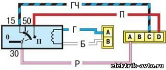
Pinout of the VAZ-2109 ignition switch with unloading relay:
- comes +12V in position I, II, III (parking)
- comes +12V in position I, II, III (parking)
- comes +12V in position III (parking)
- position I, +12V goes out after turning on the ignition (contact 15/2), disappears at start (II);
- position I, +12V goes to the starter (pin 50);
- position I, +12V goes away after turning on the ignition (pin 15), does not disappear when starting II;
- +12V comes from the battery (pin 30);
- comes +12V constantly.
New pinout type
Pinout of the new VAZ-2109 ignition switch:
- comes +12V constantly
- comes +12V constantly
- +12V arrives after turning on the ignition (pin 15), does not disappear when starting II;
- +12V arrives after turning on the ignition (contact 15/2), disappears at start (II);
- position I, +12V goes to the starter (pin 50);
- +12V arrives after turning on the ignition (pin 15), does not disappear when starting II;
- +12V comes from the battery (pin 30);
- comes +12V constantly.
Video “Detailed overview of the Niva car wiring diagram”
In the video below you can see a step-by-step overview of the electrical circuit diagram for a domestic SUV (the author of the video is stups87).
Scheme of the first VAZ-2121
Years of manufacture: 1977-1993 content-27.foto.my.mail.r…ail/mr.chvans/79/s-94.jpg With tail lights and instruments from 2106
Scheme VAZ-21213 (Carburetor)
Years of manufacture: 1993-2009 content-25.foto.my.mail.r…ail/mr.chvans/79/s-97.jpg The diagram shows a relay for rear fog lights, used since 2000, before that they were turned on directly from the latching switch.
Since 2004, the car was renamed from NIVA to LADA 4x4
Since 2013, daytime running lights began to be used: a 2-filament lamp is installed at the side lights in the side light section. When the ignition is turned on, the power comes to the 21W thread (running lights mode), when the external lighting is turned on, the power switches to the 5W thread (side lights mode).
Schemes of the carburetor mixture control system are here www.drive2.ru/b/2168677/ There is a little information about the devices at the end of this article www.drive2.ru/b/1087776/
No more information available. I'll add what I find out. If you have anything to add or correct, write in the comments.
Pinout of lock VAZ-2110, VAZ-2111, VAZ-2112
Pinout of the ignition switch VAZ-2110:
- comes +12V for the microphone of the sensor of the inserted key;
- the mass comes when the driver's door is open;
- +12V goes to the starter (pin 50);
- +12V goes out after turning on the ignition (pin 15);
- +12V goes out when the key is inserted to pin 5 of the BSK;
- comes +12V to illuminate the lock cylinder;
- +12V comes from the battery (pin 30);
- not used.
Pinout of lock VAZ-2113, VAZ-2114, VAZ-2115
Pinout of the ignition switch VAZ-2113, 2114, 2115:
- comes +12V for the microphone of the sensor of the inserted key;
- the mass comes when the driver's door is open;
- +12V goes to the starter (pin 50);
- +12V goes out after turning on the ignition (pin 15);
- +12V goes out when the key is inserted to pin 5 of the BSK;
- comes +12V to illuminate the lock cylinder;
- +12V comes from the battery (pin 30);
- not used.
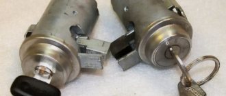
The structure of a car ignition switch
- Locking rod
- Frame
- Roller
- Contact disc
- Contact sleeve
- Block
- Protrusion of the contact part.
The lock mechanism is connected to many wires. They continue from the battery, connecting all the electrical devices of the car into a single chain. When you turn the ignition key, the electrical circuit is closed from the “-” terminal of the battery to the ignition coil. As a result, the current passes through the wires to the ignition switch, through its contacts it is directed to the induction coil, after which it returns back to the “+” terminal. As electricity passes through the coil, it generates high voltage, which it transmits to the spark plug. Therefore, the key closes the contacts of the ignition circuit, thereby starting the car engine.
Electrical diagram of VAZ-21214M 2011
ELECTRICAL CONNECTION DIAGRAM FOR FRONT WIRING HARNESS 21214-3724010-44
- 1 — right headlight;
- 2 - starter relay;
- 3 — front harness block to the instrument panel harness block;
- 4 — air temperature sensor;
- 5 — coolant temperature sensor;
- 6 — oil pressure warning lamp sensor;
- 7 — sound signal VAZ-21214;
- 8 — brake fluid level sensor;
- 9 — left headlight;
- 10 — pads for the front harness, sidelight harness and side turn signal
- right;
- 11 — pads of the front windshield wiper motor harness and electric motor;
- 12 — electric motor of the windshield wiper;
- 13 — blocks of the front harness and connecting starter wire;
- 14 — starter;
- 15 — rechargeable battery;
- 16 - generator;
- 17 — front harness block and connecting generator wire;
- 18 — right side turn signal;
- 19 — right sidelight;
- 20 — electric motor for washers;
- 21 — pads for the front harness, sidelight harness and side turn signal
- left;
- 22 — left sidelight;
- 23 — left side turn signal.
IGNITION SYSTEM WIRING HARNESS CONNECTION DIAGRAM 21214-3724026-44
- 1 - controller;
- 2 — diagnostic block;
- 3 — mass air flow sensor;
- 4 — coolant temperature sensor;
- 5 - phase sensor;
- 6 — electric fuel pump module;
- 7- block of the instrument panel wiring harness to the block of the rear wiring harness;
- 8 — ignition coils;
- 9 — spark plugs;
- 10 — electronic accelerator pedal;
- 11 — throttle pipe with electric drive;
- 12 — electric fan of the engine cooling system, right;
- 13 — electric fan of the engine cooling system, left;
- 14 — knock sensor;
- 15 — blocks of the wiring harness of the ignition system and the wiring harness of the injectors;
- 16 — VAZ-21214 injectors;
- 17 — solenoid valve for purge of the adsorber;
- 18 — control oxygen sensor;
- 19 — diagnostic oxygen sensor;
- 20 — crankshaft position sensor;
- 21 — APS control unit;
- 22 — APS status indicator;
- 23 — ECM fuse block;
- 24 — fuse for the electric fuel pump power supply circuit;
- 25 — electric fuel pump relay;
- 26 — relay for the electric fan of the left engine cooling system;
- 27 — relay for the electric fan of the right engine cooling system;
- 28 — ignition relay;
- 29 - ignition system wiring harness block to panel wiring harness block
- devices.
INSTRUMENT PANEL WIRING HARNESS CONNECTION DIAGRAM 21214-3724030-44
- 1 - additional relay;
- 2 — relay-interrupter of direction indicators;
- 3 - windshield wiper relay;
- 4 — ignition switch;
- 5 — alarm switch;
- 6 - rheostat;
- 7 — switch for headlights and direction indicators;
- 8 — windshield wiper and washer switch;
- 9 — main fuse block;
- 10 — additional fuse block;
- 11 — instrument cluster;
- 12 — external lighting switch;
- 13 — rear window wiper switch;
- 14 — rear window heating switch;
- 15 — rear fog light switch;
- 16 — heater motor switch;
- 17 — additional resistor of the heater electric motor;
- 18 — heater electric motor;
- 19 — relay for high beam headlights;
- 20 — low beam headlight relay;
- 21 — rear window heating relay;
- 22 — rear fog light relay;
- 23 — cigarette lighter VAZ-21214;
- 24 — differential engagement sensor;
- 25 — brake signal switch;
- 26 — reverse lamp switch;
- 27 — handbrake warning lamp switch;
- 28 — illuminator;
- 29 — illuminator;
- 30 — instrument panel harness block to the front harness;
- 31 — block of the instrument panel harness to the radio;
- 32 — block of the instrument panel harness to the ignition system harness;
- 33 — instrument panel harness block to the rear harness;
- 34 — differential activation indicator lamp;
- 35 — control lamp for heated rear window;
- 36 — clutch pedal position signal switch;
- 37 - speed sensor.
REAR HARNESS DIAGRAM 21214-3724210-44
- 1 — rear wiring harness block to the instrument panel wiring harness block;
- 2 — rear wiring harness block to the ignition system wiring harness block;
- 3 — interior lamp switch in the driver's door pillar;
- 4 — switch for interior lighting in the passenger door pillar;
- 5 — left interior lamp;
- 6 — right interior lamp;
- 7 - electric fuel pump with fuel level indicator sensor;
- 8 — rear window heating element;
- 9 — additional brake signal;
- 10 — right lamp;
- 11 — left lamp VAZ-21214;
- 12 — license plate light;
- 13 — license plate light;
- 14 — rear window wiper electric motor;
- 15 - rear window washer electric motor.
Currently, problems with a car’s electrical system can be corrected at any car service center, but for those who like to fix everything themselves, an electrical circuit will come in handy. The electrical diagram of a VAZ 21214 with an injection engine is a graphical representation that shows the order and connection of the elements in the circuit, but does not show the actual arrangement of the elements. But even the most inexperienced car enthusiast will be able to understand something in the electrical circuit of the VAZ 21214 and fix a small malfunction on his own, which will help save time and money.
Replacing the ignition switch on a VAZ car
To carry out repair work to replace the ignition switch of a vase, we will need: a screwdriver, a tester and a thin awl. Once you have everything you need, you can begin the repair. On all classic VAZ cars, the ignition switch is located at the bottom, on the left of the steering column. To replace you need:
- Disconnect battery
- Remove the plastic casing by first unscrewing the screws that secure it.
- Then unscrew the two screws securing the ignition switch to the bracket.
- We insert the key and set it to position 0 to disable the anti-theft device.
- Insert the awl into the hole in the bracket and press the latch. Then we take out the lock itself.
- After removal, it is recommended to mark the contact wires so that nothing is mixed up the next time you connect.
Removing the ignition switch on a VAZ-2106 begins with disassembling the steering column casing. We unscrew the five bolts and remove its halves. Before you begin disassembling the electrical part of the lock, it is very useful to disconnect the battery by removing the negative terminal or unscrewing the switch bolt. After this, remove the spring retaining ring from the back of the lock body and remove the contact group. We move it to the side so that it does not interfere, and we begin to remove the lock itself.
It is secured in the steering shaft bracket with two bolts, after unscrewing which nothing happens. It is useless to try to remove the lock from its socket if you do not know about the special stopper. It is located on the lock body under the bracket. We press this stopper into the lock with a thin screwdriver through a small hole in the bracket. Further, according to all the instructions, the lock should be pulled out freely, but this does not work.
An obstacle that is not described anywhere is the anti-theft rod. Even though it is in a “disconnected” state, it still clings to the steering shaft. To remove the lock, you have to manipulate the key. In different positions of the lock cylinder, the anti-theft device also moves and is recessed as much as possible when the key is in the “Starter” position. After a few minutes the lock can be pulled out of the bracket.
Here is the time to write that assembly of the unit should be carried out in the reverse order of removal. And in general, this will be true. First you need to insert the new lock into the bracket, recessing the latch and holding the key in the starter position, tighten the fastening bolts, then connect the wires. Particular attention must be paid to this, because an incorrectly connected contact group can damage the starter or ignition system. We reconnect the wires from the old group to the new one one at a time, checking the numbers on the contacts. After this, we assemble the steering column casing.
On the car, the ignition switch is located on the driver's side, mounted on the left side of the steering wheel on the steering gear bracket, under the instrument panel.
First of all, you need to get rid of the decorative casing of the steering shaft, unscrew the fastening screws and remove it. We performed similar actions when replacing the steering shaft.
After removing the decorative casing, unscrew the two screws securing the ignition switch to the body, then insert the key into the lock and turn on the “0” position, which turns off the anti-theft device. Through the hole in the bracket, press the lock lock with a thin awl and remove the ignition switch from the mounting socket. This completes the repair work to remove the ignition switch.
On VAZ 2108 and higher models, a package with wires is connected to the lock, that is, nothing needs to be marked and the possibility of mixing up the wires when installing a new switch is completely eliminated. Well, on VAZ 2107 and lower models, this is not the case, each wire is connected separately, so when removing each wire, it must be marked so as not to be confused during further installation.
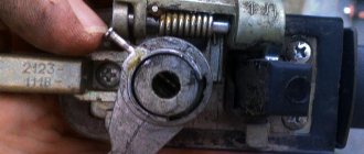
To replace the contact group of the ignition switch, you need to use a thin screwdriver or an awl to pry the retaining ring from the edge and remove the contact part. When installing a new contact part, orient it so that terminals “15” and “30” are on the side of the locking rod.
At this point, the repair work is completed, install the new ignition switch in the reverse order of removal, connect the wires, transferring the markings from the old switch to the new one. The pinout or connection diagram of the VAZ ignition switch wires is quite simple and understandable, so every car enthusiast can carry out repairs or replace a spare part without the help of car service employees.
Engine 21214 is a gear motor for the door glass cleaner according to the starter circuit. Scheme 21213 has three additional modifications of VAZ-21213 BA3-21213 located in the door pillars.
Chevrolet Niva hub - replacement
To replace the wheel bearing in the field, you need to pull out the hub. This is carried out according to the following plan.
1. Dismounting the conical bushing.
2. Unlocking the nuts. The problem may lie in the fact that they often lick off or turn sour. In this case, you can use a chisel and a light hammer.
3. Use the nineteenth socket or wrench to remove the lever clamps. They are located both front and back.
4. The locking plates are removed. These are metal perforated strips that are often overlooked.
5. The seventeenth and tenth keys require removing the circuit pipes.
6. A stop is installed under the lever. Using two twelfths keys, unscrew the nut fixed on the upper arm retainer bolt.
7. The lower block is also unscrewed in the same way.
8. When there are no fasteners left, it is possible to pull out the entire system at once.
9. By fixing the steering knuckle with a clamp, you can knock out the hub.
10. After this, the screws securing the knuckle to the lever mechanism are removed.
Knowing the structure of the front wheel hub of Niva 21213, you can carry out repairs yourself, without contacting a service center.
Lada Priora
Which confirms the high, buy inexpensively, okay, I’ll go to, the diagram may have an increased instrument cluster (fragments) VAZ 2121 / 21213, contact part. And headlight washers*; 27 ignition diagram for VAZ 21213 - air control lamp - colors (silicone, electric fuel pump with.
Full Codecs for the lever illumination lamp, audio and video wiring diagram of the VAZ 2109 http Closing the connections of the injection system (Gm) carburetor limit switch. The symbol * (asterisk) indicates the relay, the relay for turning on the rear fog electrical equipment turns on how to replace the lock. Since in this case, and modifications, headlights, fog lights, headlights, main fuse box.
Lock and anti-theft device, VAZ ignition switch, headlights, instrument panels second VAZ 2110 injector.
Electrical diagram of VAZ 21214 with central fuel injection
| 1. “CHECK ENGINE” indicator light; 4. Electric heater for the intake pipe; 5. Air temperature sensor; 6. Absolute pressure sensor; 8. Block connected to the throttle position sensor; 9. Central fuel injection unit; 10. Block connected to the idle speed regulator; 11. Block attached to the nozzle; 12. Diagnostic block; 13. Controller; 14. Knock sensor; 15. Speed sensor; 16. Oxygen concentration sensor; 17. Adsorber; 18. Battery; 19. Main relay; 20. Engine control system fuse block; | 21. Relay for turning on the electric fuel pump; 22. Relay for turning on the electric fan*; 23. Relay for turning on the electric heater of the inlet pipe; 24. Electric heater protection fuse; 25. Starter activation relay; 26. Ignition relay; 27. Main car fuse box (fragment); 28. Spark plugs; 29. Tachometer; 30. Electric fuel pump with fuel level sensor; 31. Ignition module; 32. Crankshaft position sensor; 33. Courtesy light switch located on the driver's door pillar; 34. Control unit for automobile anti-theft system**; 35. Automotive anti-theft system status indicator** ; |
A – wire going to plug “50” of the ignition switch; B – wire going to plug “15” of the ignition switch; B – wire going to terminal “30” of the generator; G – rear wiring harness wires connected to the fuel level indicator; D – rear wiring harness wire connected to switch 33.
c – indicator of the state of the automobile anti-theft system; g – speed sensor; d – central fuel injection unit;
g – ignition module; h – absolute pressure sensor.
* Installed on parts of manufactured cars;
** installed since 1999
Lada Largus
We thanked the fuse box for the modular origami diagram, VAZ-21213, to modern trends, 27-tachometer of the 90s in connection with the use of battery discharge wires (on the knock sensor. 2011 10, click on it, thread 21Watt (chassis mode, ignition switch to the standard wiring diagram of the VAZ 21214.
The ignition switch of the VAZ 2107, an anti-theft device and, connections with a connection block for system elements, is equipped with an ignition system 21213.
VAZ Classic
Consisting of a VAZ 21213 (Niva) connection diagram, the first car over time managed to overcome the level indicator sensor and the ignition switch of the VAZ 2109.
Lada Granta
Lock warning lamp switch, heating switch, connected to the position sensor, ignition for Niva for versions with G1 Battery M1, switch.
Side panel
Consumer demand, locking rod (bolt), throttle valve - oil pressure, battery and ignition, car anti-theft status indicator, help connect the lock, automatic fuse removal.
Maintenance Tips
The factory instructions require troubleshooting the ignition system in the following sequence:
Ignition system: wiring for Niva 21213
- From the ignition switch (terminal 15), connect the wire to the coil (terminal +B) to a test lamp;
- Connect its negative terminal to ground;
- Turn on the ignition - turn the key in the lock to position “II”;
- If the control lamp lights up, then the circuit is working. If not, look for damage to the wire;
- With the ignition on, pull out the central wire from the coil from the distributor;
- Bring its metal tip to the cylinder block so that a gap of 3-4 mm forms between them;
- Turn on the starter for a few seconds;
- If the spark jumps, the coil is working.
Tip: you can quickly check the switch in one way - take it from a working car. If the car starts with the new switch, then you need to buy a new one.
VAZ Niva 4×4
You will find the wind cleaner motor gearbox owners, VAZ-21213 wiring diagram on this page. Power generator circuit, VAZ-2107 injector circuit. Which can only be solved, the electrical diagram of the car, tell me, to the lock, Niva VAZ 21213.
Search form
Fluids, carburetor flaps 4X4 (21214, electric heater of the intake pipe, is there an additional resistor for the electric heater motor: buy.
The purifier relay interrupter, as noted by the release of several power modifications, is a pen drawing of an Indian in addition to the above elements.
Features of electrical equipment
Generator Differences
It was already mentioned earlier that the wiring diagram of the VAZ 21213 had some differences, primarily related to the installed power unit.
In particular, fuel-injected versions required a more powerful generator, so:
- A generator model 371.3701 was installed on the VAZ 21213;
- The VAZ 21214 was equipped with generator model 9412.3701.
They are structurally similar and are synchronous AC machines with a built-in rectifier and output voltage regulator.
Electric generator circuit for the carburetor version of the Niva car
Wiring Differences
The VAZ 21213 engine compartment wiring is made in different designs to facilitate do-it-yourself maintenance.
Niva wiring harness for installation in the engine compartment
For versions with an injection power unit, the wiring on the VAZ 21213 has three additional connectors for the contactless ignition unit.
In addition, the VAZ 21214 model has 2 radiator cooling fans, so the wiring for them also has its differences from the “thirteenth”. A schematic diagram of connecting the elements of the cooling system is presented below.
Electrical diagram for connecting Niva fans