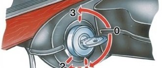
You can visually see how the components behave in different positions of the ignition key. For example, in the “ignition on” position, all electrical equipment should work. If you turn the key to the "starter" position, it should work and start the engine.
To be sure that the problem is in the lock, you need to carry out simple diagnostics. To do this, we need a multimeter with a resistance measurement function.
We perform the following actions:
- Remove the negative terminal from the battery.
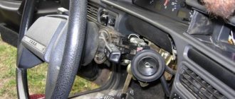
- We dismantle the plastic casings around the lock.
- We disconnect the power connector from the lock and remove it to gain access to it.
- Place the multimeter in the resistance measurement position.
- We connect the probes to pins seven and four, corresponding to pins 30 and 15.
- Turn the key in the lock to the “ignition on” position and remember the resistance readings.
- Turn off the ignition and connect the probes to contacts three and seven, corresponding to contacts 30 and 50.
- Turn the key in the lock to the “starter” position and remember the readings.
The resistance will be “zero” in both cases if the lock is working properly. If there is any resistance, we do not recommend replacing the contact group of the ignition switch on VAZ 2113, 2114, 2115. It is best to change the complete lock.
In the technical documentation for the VAZ-2114 there is a separate section that specifically describes the design of the vehicle’s electrical equipment. So, all the elements are described in full. But, in this particular case, the issue of independently connecting the ignition wires will be considered.
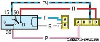
So, let's look at the diagram to see how the contact connections of the ignition switch are connected.
Ignition switch pinout diagram
Regardless of the ignition being turned on, the following devices can operate: high beam, interior and instrument panel lighting, hazard lights, brake light, sound signal, as well as exterior lighting.
A separate item worth highlighting is additional equipment: a car radio (of any format), speakers, additional lighting devices are powered directly into the battery or on-board network, and much more.
Ignition switch device
Next, we will consider the switched circuits of various key positions in the ignition switch:
| Key position | Live contacts | Switched circuits |
| 0 (Disabled) | 30 | _ |
| 1 (Ignition) | 30-15 | Ignition system, generator excitation, headlights, turn signal, control devices, windshield and headlight cleaners and washers, heater fan motor, rear window defroster, cigarette lighter |
| II (Starter) | 30-15 | See Regulation I |
| 30-50 | Starter |
Ignition switch pinout
Product selection
There are several options for the ignition switch on the VAZ-2114. Let's look at each one separately:
- 2110-3704005 or KZ-881 – original catalog numbers of the ignition switch manufactured by AvtoVAZ. The wiring diagram is standard, that is, factory. Installation is quite easy. The average cost is 1000 rubles .
Pinout of lock VAZ-2108, VAZ-2109, VAZ-21099
Pinout according to the old type
Pinout of the VAZ-2109 ignition switch with unloading relay:
- comes +12V in position I, II, III (parking)
- comes +12V in position I, II, III (parking)
- comes +12V in position III (parking)
- position I, +12V goes out after turning on the ignition (contact 15/2), disappears at start (II);
- position I, +12V goes to the starter (pin 50);
- position I, +12V goes away after turning on the ignition (pin 15), does not disappear when starting II;
- +12V comes from the battery (pin 30);
- comes +12V constantly.
New pinout type
Pinout of the new VAZ-2109 ignition switch:
- comes +12V constantly
- comes +12V constantly
- +12V arrives after turning on the ignition (pin 15), does not disappear when starting II;
- +12V arrives after turning on the ignition (contact 15/2), disappears at start (II);
- position I, +12V goes to the starter (pin 50);
- +12V arrives after turning on the ignition (pin 15), does not disappear when starting II;
- +12V comes from the battery (pin 30);
- comes +12V constantly.
Ignition system and starter connection diagram
VAZ 2114 button connection diagram
Power window relay contacts. This is what determined its popularity among domestic car enthusiasts, see. In general, it is a rather practical and interesting model, and accordingly, this led to the fact that it became so popular among our car enthusiasts. Remove the fitting from the drain pipe and set it aside.
Tip: replacing VAZ wiring is often accompanied by damage to the mounting clips. To prevent the battery from discharging, the battery must be recharged from time to time, especially before the onset of cold weather and at the end of winter. Gasoline is supplied from the gasoline pump located in it.
Among the most noticeable modifications are the visible parts of the body, see Rear window heating relay contacts. The electrical network includes many components, and if the main components fail for some reason, this can seriously affect the performance of the vehicle. In general, it is a rather practical and interesting model, which is why it has become so popular among our car enthusiasts. The battery charging circuit, the ignition and engine start circuits, the generator are not protected by fuses, with the exception of the excitation winding, the winding of the headlight switch relay and the door lock system relay. Wiring VAZ 2115. Part 1.
Instructions for replacing the ZZ
Replacing the ignition switch on a VAZ 2114 injector takes place in stages. At each stage certain actions are performed.
Preparation
First of all, you should prepare for the replacement procedure by preparing an electrical circuit diagram and the necessary materials and tools:
- new node;
- 4 assembly mounting screws;
- chisel;
- a set of keys;
- Phillips screwdriver;
- hammer;
- pliers.
The VAZ 2114 ignition switch should be purchased assembled.
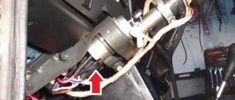
ZZ for a VAZ car
For ease of operation, remove the cover from the steering column and switches.
Dismantling the casing is carried out step by step:
- First of all, the car is de-energized by disconnecting the negative terminal from the battery.
- Use a Phillips screwdriver to unscrew the screws securing the casing.
- Then the self-tapping screw is unscrewed, with which the housing is secured.
- Now you need to remove the screws holding the lower part of the housing to the steering column.
- At the next stage, the lever is lowered down, with the help of which the steering column is fixed at the angle, and the steering wheel.
- Next, the lower casing is dismantled.
- After disconnecting the power supply, you can remove the upper part of the casing.
- To remove the steering column switches, press the locking elements and remove the elements from their standard places.
- The switches should also be disconnected from the power supply.
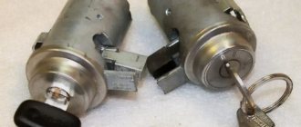
Removing a faulty device
Having opened access to the protection zone, you can dismantle it. The difficulty of dismantling is that there are no heads on the 4 bolts that secure the ignition switch to the steering column on the VAZ 2114. The absence of heads prevents criminals from stealing a car without a key.
Dismantling with hammer and chisel
Dismantling of the protection zone is carried out as follows:
- you need to loosen the bolts using a hammer and chisel;
- then the loosened bolts are removed with pliers;
- then the bracket is removed from the steering column;
- the power supply is turned off;
- Now you can dismantle the unit.
The node connection diagram is simple. If it is purchased assembled, then it is not difficult to understand the diagram in order to connect the wires correctly.
Installing a new lock
The procedure for installing the ignition switch on a VAZ consists of the following steps:
- first you need to install the key in the new unit in position “I”, then the latch, thanks to which the steering wheel is locked, will hide;
- then the protection is mounted and the actions are performed in the reverse order of removal;
- After tightening the 4 bolts, you need to tighten them a little.
After installing the new unit, you need to check the steering lock. To do this, remove the key from the lock and turn the steering wheel to a small angle. If the steering wheel does not lock, you must install the unit correctly: the latch must fit into the groove located on the steering column. If the locking function works, all you have to do is tighten all the breakaway bolts until they stop. You need to tighten them until the heads are broken.
When replacing the VAZ ignition switch is completed, you need to connect the power and check the functionality of the device by starting the engine.
Steering lock testing
Steering wheel testing
If you don't check the steering lock, you may encounter certain problems in the future. Therefore, do not waste your time on this event. It consists of removing the key from the ignition and turning the steering wheel at a slight angle.
- If there is no lock, you will need to slightly adjust the position of the lock. Make sure it fits into the groove located on the steering shaft.
- If the locking is effective, you will only need to tighten the four installed breakaway bolts until they stop. Twist until the heads break.
It is worth noting one very important nuance. Some people don't find it necessary to use breakaway bolts. Instead, the most common fixing bolts with a length of 20 millimeters and an M6 thread are used. On the one hand, this will make it easier to remove the device in the future, if such an event is required again. On the other hand, in the absence of a reliable anti-theft system, voluntarily giving attackers access to your car is not the best idea.
When the lock installation is completed and the test has passed, do not forget to connect the device to power and start the engine. If it starts, all systems dependent on the ignition switch are working, you can fully begin reassembly. Follow the reverse instructions for removing the casing and steering column switches. It would not be amiss to check the condition of certain nodes along the way. It is quite possible that some of them also need replacement or a little preventive maintenance.
Loading …
Ignition switch VAZ 2110, 2111, 2112
The content of the article:
Checking the serviceability and diagram of the ignition switch for VAZ 2110, 2111, 2112
The ignition does not turn on on the VAZ 2110? One of the causes of the disease may be in the ignition switch. Don’t rush to replace the ignition switch with a new one, first try checking it yourself.
Malfunctions of the ignition switch VAZ 2110
To determine if the ignition switch is faulty, just check it. Install the key and check the resistance of the contacts with an ohmmeter when switching modes 1, 2, 3 with the key. If the ignition switch is working, then the resistance of the selected contacts should be equal to 0.
VAZ 2110 ignition switch diagram
Ignition switch pinout: 1. +12V is supplied for the sensor mic of the inserted key; 2. The mass arrives when the driver's door is open; 3. +12V goes to the starter (pin 50); 4. +12V goes out after turning on the ignition (pin 15); 5. +12V goes out when the key is inserted into pin 5 of the BSK; 6. +12V is supplied to illuminate the lock cylinder; 7. +12V comes from the battery (pin 30); 8. Not used.
Repair of ignition switch VAZ 2110
Just like that, for no reason, the ignition switch broke. The ignition turns on, but the starter does not turn and does not pump the pump. I started to disassemble the steering gear casing... I got to the lock and... I really wanted to invite the VAZ designer to visit... and ask him to unscrew his ignition switch mounting bolts (“special anti-theft bolts”) The bolts are hardened, with a smooth, even head. They did everything they could... they twisted it, made notches, the bolts did not budge... Apparently, no one had removed the lock since the car was manufactured (2005).
After many attempts to “culturally” remove the lock and see what happened to it, a decision was made, with the help of a sledgehammer and some kind of mother, to remove the lock as it turned out...
After several precise blows, the castle surrendered...
The cause of the lock breakdown was a popped-out ball of the steering wheel locking mechanism... During disassembly, it turned out that it was necessary to change the installation location of the steering column switches and the turn/light switch.
When I bought a new lock, I immediately bought and installed simple bolts under a shaped screwdriver... just in case.
Pinout of buttons on the Europanel and connection of buttons in VAZ 2110, 2111, 2112
Yesterday I purchased a euro panel and the first question arose: how can I install it using my old wiring?
Pinout of mounting block 2113, 2114, 2115
Diagram of the VAZ-2113, 2114, 2115 mounting block Option No. 1.
K1–relay for turning on headlight cleaners; K2–relay-interrupter for direction indicators and hazard warning lights; K3 – windshield wiper relay; K4 – lamp health monitoring relay; K5 – power window relay; K6 – relay for turning on sound signals; K7 – rear window heating relay; K8 – headlight high beam relay; K9 – relay for turning on low beam headlights;
Diagram of the VAZ-2113, 2114, 2115 mounting block Option No. 2.
Numbering of plugs in the connecting blocks of the VAZ 2113, 2114, 2115 mounting block
New model mounting block VAZ-2113, 2114, 2115. Location of fuses and relays.
K1–relay for turning on headlight cleaners; K2–relay-interrupter for direction indicators and hazard warning lights; K3 – windshield wiper relay; K4 – lamp health monitoring relay; K5 – power window relay; K6 – relay for turning on sound signals; K7 – rear window heating relay; K8 – headlight high beam relay; K9 – relay for turning on low beam headlights; F1–F20—fuses; X11 – terminals of the wiring harness block
Table of circuits protected by fuses on the VAZ 2114
Installing a new device
Now you can finally proceed directly to replacing the broken or worn out ignition switch on your VAZ2114 car.
Removing the ignition switch
To do this, follow the following sequence of actions:
- Insert the key into the new lock and turn it to the first position. This will allow the latch, which is responsible for locking the steering shaft, to hide inside the housing structure;
- Insert the lock into place following the reverse dismantling sequence;
- Install the four retaining bolts and tighten them slightly.
Troubleshooting Methods
There are two methods for detecting faults:
Ignition switch circuit
We suggest studying a visual method for determining a malfunction or breakdown of the contact elements of the ignition switch using the table.
| Action | The device is working properly | The device is faulty |
| Turn the key to the right position (ignition) | All electrical equipment turns on | All or part of the electrical equipment does not work |
| Turn the key to the second position | The starter is spinning | The starter does not work, the traction relay does not click under the hood |
To work, you will need a mini-tester and a multimeter in ohmmeter mode:
- Disconnect the power supply from the ignition switch. To do this, you need to remove the skin from the steering column;
- Switch your multimeter to an ohmmeter;
- On the block coming from the lock you need to find pins 7 and 4, which correspond to pins 15 and 30;
- Connect the multimeter probes to them;
- Turn the key to the “Ignition” position;
- On the block, find pins 7 and 3, corresponding to 50 and 30. Also connect a multimeter to them;
- Turn the key to the second position - Start the engine;
- If serviceability is present, the device will show zero resistance in both test cases.
Replacing the ignition switch VAZ-2109 carburetor, injector step-by-step video instructions
One of the main components of the VAZ-2109 can be called the ignition switch; the successful start of the car and the operation of elements dependent on the electrical network depend on it. Usually it works for a long time, trouble-free, and breaks down extremely rarely, but if this happens, then replacement is inevitable. Some car enthusiasts have driven half their lives and never encountered this problem, others are less fortunate. In any case, in order to confidently drive on the roads, it is advisable to know how to replace this element of the car yourself.
Device
On the VAZ-2109 you can find the ignition of a new, as well as an old model. Older models have 4 positions, a long key and a relay. The new ones have 3 positions and a short key, but there is no relay at all. The ignition switch in the VAZ-2109, as well as in other cars, is designed to perform two functions: to lock the steering column (mechanical) and to close contacts when turning the key (electrical).
The electrical part works depending on the turn of the key:
- car de-energized – 0;
- voltage supplied to the entire electrical network – 1;
- supplying current only to the starter – 2;
- turning on emergency lighting.
Malfunctions
Considering that the ignition switch is designed to perform two functions, all breakdowns are divided into mechanical and electrical. Mechanical malfunctions include jamming of the cylinder in one of the positions when it is impossible to turn the key. Contact group, which is time to change when the car engine does not start when you turn the key or deformation has occurred.
Electrical faults can occur in any position of the key, as they are associated with a violation of the integrity of the electrical network.
In a situation where there is no contact, all components of the system do not function. If there is a contact in the wrong place, a short circuit and overheating will occur, which will lead to the need to install a new lock.
Ignition replacement and check
To replace the ignition switch, you need to perform all the steps in a certain sequence:
- Before replacing, you must remove the negative terminal from the battery.
- Remove the steering column cover and the two switches located under the steering wheel.
- After this, you need to insert the key into the ignition switch and set it to the zero position. This is necessary for the anti-theft device to be disabled.
- Next, unscrew the 4 bolts that hold the ignition switch. If bolts with sheared heads are installed, knock them down using a hammer and chisel.
- After unscrewing (knocking down) the bolts, remove them from the holes using pliers.
- On the left side, remove the bracket, and then on the right side, remove the ignition switch.
- Then disconnect the wire block from the electrical connector.
- Get under the dashboard and disconnect the ignition switch connectors from the relay.
Installing a new lock must be done step by step in reverse order.
To check the contacts on the wire block, use an ohmmeter. The device must display zero. If his readings are different, change the contact group.
To change a contact group, you need to do the following:
- Using a screwdriver, unscrew the screw that secures the cover.
- Bend back the plastic latches that hold the cover in place, then remove it.
- Remove the contact group.
The contact group is also installed in the reverse order.
Not in all cases it will be possible to find four bolts on the steering column on a VAZ-2109. On some models it can be secured with two bolts and a hook.
Checking the Lada Samara ignition module
The correct functioning of the ignition module not only has a significant impact on the start of the vehicle’s power plant, but also ensures the stability of its operation in all modes. To carry out a complete diagnosis of this electronic device, you need quite complex equipment, available only in large specialized workshops. However, you can check the functionality of the ignition module yourself in an amateur garage. The only logistical support for this test will be a multimeter, or tester.
Attention! When using a donor car for testing, do not forget that only the first Lada Samara models were equipped with the ignition module, as a separate device. Machines of later releases are equipped with separate type devices (the switch is included in the electronic control unit).
The procedure for replacing the ignition module includes the following steps:
The procedure for replacing the ignition module includes the following steps:
Another method involves measuring the resistance of individual module elements using a multimeter (tester). Using the tester probes, we close the “paired” terminals of the module, which provide connection to high voltage wires, and measure the resistance value.
There is another, so-called “folk” method, or the “shake-up” method. With the power plant running, lightly tap the module. Despite all the “technical non-scientific” nature of such manipulations, they are capable of producing results. True, only in the case when the contact of the elements inside the housing is broken.