Replacing and adjusting the ignition module on a VAZ 2107
The VAZ 2107 ignition module (injector) is a unit whose malfunctions are quite difficult to diagnose.
Problems with the module's operation are noticed only after serious engine malfunctions occur. If the engine does not start, you should try adjusting the ignition. If the engine is running unevenly, a serious check of the functionality of the VAZ 2107 ignition module may be required. Ignition is an electronic system for converting the low voltage of the vehicle's on-board network into high voltage and supplying the latter to the electrodes of the spark plugs.
Diagnostics of malfunctions of the ignition module of injection VAZ 2107
The ignition of the injection VAZ 2107 is completely electronic and is considered quite reliable. However, problems can arise with it too. The module plays an important role in this.
Signs of a malfunctioning ignition module
Symptoms of a faulty module include:
- the Check engine warning light on the dashboard lights up;
- floating idle speed;
- engine tripping;
- dips and jerks during acceleration;
- change in sound and color of exhaust;
- increased fuel consumption.
However, these signs can also appear in case of other malfunctions - for example, in case of problems with the fuel system, as well as in case of failure of some sensors (oxygen, mass air flow, detonation, crankshaft position, etc.). If the engine starts to operate incorrectly, the electronic controller puts it into emergency mode, using all available resources. Therefore, when the engine operation changes, fuel consumption increases.
In such cases, you should first of all pay attention to the controller, read information from it and decipher the error code that has occurred. To do this, you will need a special electronic tester, available at almost any service station. If the ignition module fails, error codes in engine operation may be as follows:
- P 3000 - no sparking in the cylinders (for each cylinder the code may look like P 3001, P 3002, P 3003, P 3004);
- P 0351 - break in the winding or windings of the coil responsible for cylinders 1–4;
- P 0352 - a break in the winding or windings of the coil responsible for 2–3 cylinders.
At the same time, the controller can produce similar errors in the event of a malfunction (break, breakdown) of high-voltage wires and spark plugs. Therefore, before diagnosing the module, you should check the high voltage wires and spark plugs.
Main malfunctions of the ignition module
The main malfunctions of the VAZ 2107 ignition module include:
- a break or short to ground in the wiring coming from the controller;
- lack of contact in the connector;
- short circuit of the device windings to ground;
- break in the module windings.
Checking the ignition module
To diagnose the VAZ 2107 injection module, you will need a multimeter. The verification algorithm is as follows:
- Raise the hood, remove the air filter, find the module.
- We disconnect the block of the wiring harness coming from the controller from the module.
- We set the multimeter to measure voltage in the range 0–20 V.
- Without starting the engine, turn on the ignition.
- We connect the negative (usually black) probe of the multimeter to ground, and the positive one to the middle contact on the harness block. The device must display the voltage of the on-board network (at least 12 V). If there is no voltage or it is less than 12 V, the wiring or the controller itself is faulty.
- If the multimeter shows a voltage of at least 12 V, turn off the ignition.
- Without connecting the connector with wires, disconnect the high-voltage conductors from the ignition module.
- Switch the multimeter to resistance measurement mode with a measurement limit of 20 kOhm.
- To check the device for an open circuit in its primary windings, we measure the resistance between contacts 1a and 1b (the outermost ones in the connector). If the resistance of the device tends to infinity, there is indeed an open circuit in the circuit.
- We check the module for breaks in the secondary windings. To do this, we measure the resistance between the high-voltage terminals of the first and fourth cylinders, then between the terminals of the second and third cylinders. In operating condition, the module resistance should be about 5–6 KOhm. If it tends to infinity, the circuit is broken and the module is faulty.
Video: checking the ignition module of the VAZ 2107
Checking the ignition system elements
Misfires in engine operation, especially in wet weather, are a consequence of breakdown of the insulation of high-voltage wires. There should be no cracks or damage in the wire insulation. You can check the insulation for breakdown using a wire connected to ground. If you run it along the insulation while the engine is running, a spark will be observed in places with damaged insulation. Another clear sign of poor insulation is noticeable electric shocks when touching high-voltage wires while the motor is running.
A broken high-voltage wire can be easily determined with an ohmmeter. The resistance should be between 3-10 kOhm. The spread of indicators between the wires should be no more than 1-2 kOhm.
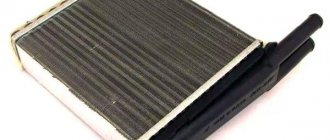
High voltage wires
High voltage wires (HVW) transmit impulses from the coil to the spark plugs. Unlike other wires, they must not only withstand high voltage, but also protect other parts of the car from it. Each wire consists of a conductor with a metal tip, rubber caps on both sides and insulation. The serviceability and reliability of the insulation is of great importance, since it:
- prevents moisture from entering the conductive element;
- reduces current leakage to a minimum.
Malfunctions of high-voltage wires
The following main malfunctions are characteristic of GDP:
- breakage of the conductive element;
- voltage leakage due to poor insulation;
- excessively high wire resistance;
- unreliable contact between the GDP and the spark plugs or its absence.
If the VV is damaged, the electrical contact is lost and a discharge occurs, leading to voltage loss. In this case, the spark plug receives not the rated voltage, but an electromagnetic pulse. Faulty wires lead to improper functioning of some sensors and interruptions in the operation of the power unit. As a result, one of the cylinders stops performing useful work and runs idle. The power unit loses power and begins to detonate. In this case, they say that the engine is “troubling.”
One of the malfunctions of high-voltage wires is a break
Diagnostics of high-voltage wires
If you suspect a malfunction of the engine (the engine is “troubling”), they must first be carefully inspected - damage to the insulation, chips, or contact with hot engine elements is possible. Particular attention should be paid to the wire contacts - there should be no traces of oxidation or soot on them. If no visible damage is found, proceed to detect a possible break and measure the resistance of the GDP using a multimeter. The wire resistance should be 3–10 kOhm. If it is zero, the wire is broken. It should also be taken into account that the resistance should not deviate from the norm by more than 2–3 kOhm. Otherwise, the wire should be replaced.
Selection of high voltage wires
When purchasing new wires, you should pay attention to the car manufacturer's recommendations. The VAZ 2107 is usually equipped with VPPV-40 (blue) wires with distributed resistance (2550 +/-200 Ohm/m) or PVVP-8 (red) with distributed resistance (2000 +/-200 Ohm/m). An important indicator of GDP is the permissible voltage. If the actual voltage values exceed the permissible values, breakdown of the cable insulating layer may occur and the wire may fail. The voltage in a non-contact SZ reaches 20 kV, and the breakdown voltage is 50 kV.
The material from which the GDPs are made is also important. Typically the wire has polyethylene insulation in a polyvinyl chloride sheath. Silicone GDPs are considered the most reliable. They do not become rough in the cold, which prevents them from loosening in their nests, and are less prone to breakdowns. Wire manufacturers include Champion, Tesla, Horse, and others.
Tesla products are considered one of the most reliable
Signs of breakdown
When the ignition is turned on, the engine ECU malfunction indicator light comes on, and after the engine is started, it should go out. A burning warning light is the first sign of problems with the ignition system. Other prerequisites for diagnosing the ignition module are “floating” engine speed and problems with starting. The cause of such failures may be faulty high-voltage wires or spark plugs, so you need to make sure they are working before you start diagnosing the ignition of the VAZ 2107 (injector). Often, cylinder misfires occur due to compression problems or damage to the intake manifold gasket. This must be taken into account when searching for the causes of engine failure.
What are the advantages of VAZ 2107 injection models?
• The VAZ 2107 injection engine consumes less fuel. At the same time, it is more powerful than a carburetor engine with the same volume. This is achieved through the optimal formation of the qualitative and quantitative composition of the fuel mixture. Accordingly, the efficiency of an injection engine is higher than that of a carburetor.
• Thanks to electronic speed control, the engine runs more reliably at idle, stalls less when starting, and starts well at low ambient temperatures.
• Compared to a carburetor engine, an injection engine does not require frequent adjustments to the ignition and fuel supply systems.
• The air-fuel mixture that enters the cylinders has the most favorable composition. And the existing catalyst controls the minimum amount of harmful exhaust gases. This plays a big role in preserving the environment and taking care of health.
Checking the ignition coil
The coil is checked based on two indicators: the presence of a short circuit and an open circuit. Before diagnostics, the ignition coil must be disconnected. After this, one probe of the device is connected to the central contact of the coil, the second to the body (ground). If the display shows resistance equal to infinity, there is no short circuit.
The primary winding of the coil for a break occurs differently. The probes of the device must be connected to the right and left contacts. The resistance between them should be within 3-3.5 Ohms.
If the resistance of the primary winding does not correspond to the norm or there is a short circuit in the coil to the housing, it must be replaced.
Ignition adjustment
The injection modification of the VAZ 2107 does not require adjustment of the ignition timing. The electronic control unit, using a sensor, determines the optimal ignition timing. The participation of the car owner in adjusting the operation is limited to setting the engine timing belt to the marks.
To check the performance of the ECU and the functionality of the sensors, it is necessary to connect a computer with specialized software. In this way, the cause of most electronic ignition system malfunctions can be determined.
It is also worth checking the operation of the throttle position sensor yourself. When the throttle is closed, the voltage on the sensor should be no higher than 0.55 volts, and when fully open - 4.5 volts. Measurements must be made with a voltmeter with the ignition on.
Ignition module
The ignition module is a device designed to convert DC voltage from the on-board network into electronic high-voltage pulses with their subsequent distribution among the cylinders in a certain order.
Design and operating principle
The design of the device includes two two-terminal ignition coils (transformers) and two high-voltage switches. The voltage supply to the primary windings of the transformer is controlled by the controller based on the information received from the sensors.
In the ignition system of an injection engine, voltage distribution is carried out according to the idle spark principle, which provides for the pairwise division of cylinders (1–4 and 2–3). A spark is formed simultaneously in two cylinders - in the cylinder in which the compression stroke is coming to an end (working spark), and in the cylinder where the exhaust stroke begins (idle spark). In the first cylinder, the fuel-air mixture ignites, but in the fourth, where the gases burn out, nothing happens. After turning the crankshaft half a turn (180 0), the second pair of cylinders enters the process. Since the controller receives information about the exact position of the crankshaft from a special sensor, problems with sparking and its order do not arise.
Location of the ignition module VAZ 2107
The ignition module is located on the front side of the cylinder block above the oil filter. It is secured to a specially designed metal bracket using four screws. It can be identified by the high-voltage wires coming out of the housing.
How to set the ignition on a VAZ 2107
The ignition module is a mechanism whose malfunctions are very difficult to identify. Usually, problems begin to be solved when it becomes obvious that something is wrong with the car. If your VAZ 2107 does not start the first time, you cannot set the ignition, and uneven engine operation begins to confuse you - it’s time to carry out a proper check. Let us recall that the engine ignition module of the “injector” type is the same system that, with the help of coils, supplies electrical energy in order to form a spark and start the car.
Practical recommendations for working with the ignition module
The ignition module is one of those mechanisms in which it is quite difficult to determine the presence of malfunctions. They pay attention to it when serious deviations in the operation of the car are observed. If the VAZ 2107 engine does not start immediately, it is recommended to adjust the ignition, and if the engine is running unevenly, a proper check is required. The main thing here is not to forget that the ignition module of an injection engine is a system that, using coils, generates electrical energy to generate a spark and further start the vehicle.
- Prerequisites for failure
- Preparation stage
- The key to high-quality circuit testing
Prerequisites for failure
Please note that the engine management system malfunction warning lamp, located on the instrument panel in the indicator block, is the first indicator of deviations in the operation of the VAZ 2107, which uses an injector. Some modifications of the VAZ 2107 provide for the location of the warning lamp on the upper insert of the radio panel. By starting the ignition, a system malfunction is tested, which means the lamp lights up and goes out after the engine starts. A prerequisite for diagnosing the ignition system is that the lamp does not go out while the engine is running.
In situations where there is a malfunction, VAZ 2107 owners replace the spark plugs. Old factory spark plugs are usually replaced with iridium spark plugs from NGK or Denzo. Do not forget that only those spark plugs that are designed for the appropriate type of injection are suitable here.
The type of ignition system is no less important in determining the parameters of the spark plug. Often such manipulation does not provide much improvement (plugs have a fairly long service life), so the non-contact ignition system undergoes a full diagnosis.
Preparation stage
Diagnostics of how the ignition module and each individual coil operates is carried out using a special device called a multimeter or ohmmeter. Its functional task is to show the voltage value supplied by the ignition module. As a result of diagnostics, it is possible to identify the source of current loss in the circuit and, accordingly, the nature of the malfunction. To facilitate painstaking work, it is recommended to dismantle the module outward before starting the process.
Proper short circuit check
First, check the coil winding for short circuits. To do this, you need to connect a multimeter that determines the resistance. Before checking, it is recommended to lubricate the tip of the high-voltage wire with a special lubricant, which can be purchased at any spare parts store for the VAZ 2107, or with technical petroleum jelly.
We disconnect the module from the tips and connect one terminal of the device to the central contact that the coil has, and the other to ground. If the device display shows “infinity”, this means that there is no short circuit - that is, everything is in order. It is worth noting that if, when ringing the circuit, the display indicators did not change (and, for example, the number one was preserved), then this is infinity.
Now let's check the primary ignition circuit for an open circuit.
To do this, you will need to install a multimeter to the left and right contacts, which are responsible for the ignition function. With this installation, the ohmmeter should change its readings. Otherwise, it will be not just the coil that needs to be replaced, but the entire device. Please note that the normal value is 3-3.5 ohms.
The key to high-quality circuit testing
The contactless ignition system checks for short circuits. First, pay attention to the coil winding. To get started, connect a multimeter, which determines the resistance value. There is a recommendation regarding the lubrication of the tip of a high-voltage wire: a special product for the VAZ 2107 or technical petroleum jelly is used here.
The coil itself is diagnosed as follows:
- the module is disconnected from the tips;
- one terminal of the device is connected to the central contact, which has a coil;
- the other terminal of the device is connected to ground.
If the display of the infinity device indicates that there is no short circuit, then the coil is in order. Important: unchanged display indicators when ringing the circuit will indicate infinity.
Checking the primary ignition circuit involves installing a multimeter to its left and right contacts, which are assigned the ignition function. This setting of the ohmmeter should cause a change in readings. If this is not observed, you can prepare not only to replace the coil, but the entire device. Here they focus on the norm, which is 3-3.5 ohms.
The process of checking the secondary windings of the module includes:
- Disconnecting wire tips from it.
- Level position in front of you.
- Installing the module to the right outputs of the upper and lower locations. We focus on the indicators that the device displays in seconds.
- The previous manipulation is carried out similarly with the left outputs of the upper and lower locations.
Here we focus on an indicator whose value will be no less than 7 ohms. Recommendation: if at least one coil does not meet the specified indicator, the module as a whole must be replaced, otherwise it will not be possible to avoid a malfunction of the system with a VAZ 2107, where an injector is used.
First, let's decide which of the four cylinders is first?
The first cylinder in front-wheel drive VAZs is located closer to the timing belt. If you look at the engine from the front, the first cylinder is the leftmost). And then everything is simple - from left to right - 1, 2, 3, 4.
In rear-wheel drive VAZ Classic and Niva, the first cylinder is located closer to the front bumper of the car.
The product portfolio for electrical installations additionally includes various spacers for mounting floodlights in insulated ceilings and acoustic ones. For example, safety is taken into account from the very beginning of product design. In addition, our portfolio includes automatic clamps that can be used in any socket, wall or recessed box. In the field of electrical installations, insulating tapes can be used, among other things, for insulating, fastening, gluing, waterproofing and identifying cables.
Checking high-voltage wires. To check the wires, you will need a multimeter tester. Check the resistance of the wires - it should be no more than 20 KOM (in practice, the longest wire of 1 cylinder has a resistance of up to 10 KOM). If the wire resistance is more than 20 Kom, it must be replaced. Carefully inspect the wires for chafing on parts of the motor or other wires. In case of significant abrasion, replace the wire. In case of minor abrasion, it is possible to lay the wire so that it does not rub and fix it in this position.
Automatic clamps are ideal for professional electrical installations in buildings and buildings. Different colors make it easy to distinguish automatic clamps in electrical installations. It is a multi-functional tool that simplifies any cable installation. These push-pull sensors are available in a variety of kits, each consisting of a durable carrying bag and various useful accessories. Thanks to the fiberglass reinforcement, cable installation is also greatly facilitated in hard-to-reach areas, saving time.
Laying wires. Do not try to connect the wires in a bundle. Disassemble the wiring harnesses, release the wires from the plastic holders. Connect the high-voltage leads to the corresponding cylinder spark plugs. Lay the wires so that they do not rub against each other, engine parts, or hoses. Avoid sharp bends and tension on the wires. After connecting all the wires, secure them into the bundle with special comb holders included in the delivery kit.
Spotlights installed in countertops create so much heat that they can cause overheating or cause insulation materials to leak, causing dangerous fires. This innovative product can be easily inserted into panels or drywall during electrical installation, allowing air to circulate around the floodlight and thus avoid dangerous overheating.
These gaskets also extend the life of the built-in floodlights. Rubber bands can be used to waterproof and insulate cables and connections in low, medium and high conditions. Fabric straps are extremely durable and ideal for identifying, securing and repairing cables. Insulating tapes are ideal for low voltage applications and are available in a variety of sizes and colors.
The procedure for connecting I/O wires to a VAZ carburetor (2108, 2109, 21099)
The central wire from the distributor cover always goes to the ignition coil (bobbin).
The outlet of the distributor cover, which faces towards the front of the car, is connected to the first cylinder.
Insulating tapes can be used to waterproof and insulate cables and connections in low and high voltage applications. Tapes are available in different colors and sizes and are useful for a variety of applications. They are very tear resistant and can be written on.
To help installers in their daily work: connecting lines and electrical devices in civil applications require adequate tools to make their use fast, easy, safe and efficient. We develop solutions for our customers that meet industry-specific needs, meet application needs, reduce installation and component costs, and improve the quality of the final product. Thanks to their compact design, the range clamps allow cable connections in civil installations with limited space.
The outlet of the distributor cap, looking down, is connected to the third cylinder.
The outlet of the distributor cap, looking rearward, is connected to the fourth cylinder.
Checking the secondary windings of the module
First, disconnect the wire ends from it. If you have already done this, then place it exactly in front of you. Then install the device to the upper and lower right outputs and carefully monitor the indicators that the device will display in a second.
After this, we perform exactly the same actions with the upper and lower left exits. Naturally, the ohmmeter readings should change and ideally be at least 7 ohms.
If at least one coil does not meet the standards, then in order to avoid unforeseen situations with your VAZ 2107, we recommend replacing the entire module.
How to remove the coil
If your fears are confirmed, and the coil really needs to be replaced, then installing a new one will not be difficult.
To do this, first remove the air filter housing, then the negative wire terminal from the battery and disconnect the high-voltage wires from the module. Having removed the wires located there from the module cover, unscrew the three nuts that secure it and disconnect it from the bracket.
That's all. Even a novice VAZ 2107 driver can perform such simple manipulations. If you already have a new part, then immediately after removing the coil you can install it. To do this, you need to perform all the steps we previously described in reverse order.
If it happens that you suddenly forgot how the high-voltage wires were originally located, then thanks to one little hint from a caring manufacturer, you won’t have to fiddle around for long. The secret is that on the module itself the numbers of the cylinders to which the wires must be connected are indicated.
How to replace the starter relay
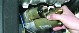
A common problem on carburetor engines is the failure of the starter relay. When the key is turned in the lock, a click is heard, but the relay does not respond. Replacing a relay is not such a difficult task.
Remove the starter from it. Unscrew the 2 bolts that secure it. Tilt it to the right and remove it by turning the back wall. Unscrew the nuts that secure the relay and starter. Remove the terminal by turning it to the side. Remove the relay, first unscrew the bolts. Install the new relay in the same way, only the actions will be in the opposite direction. When replacing this important part, the VAZ-2107 car will last for a long time. As you can see, the procedure is simple, and you can do it yourself.
Setting the ignition
Another important problem among VAZ 2107 owners with an injector system is how to accurately set the ignition.
As you know, in such models, all engine control is carried out electronically, so for such work you will need a computer, installation of a special program on it for the engine of an injection car, a tester, as well as keys and screwdrivers.
First of all, turn on the ignition and ground to make sure the electric pump is working. If it does not work, then check the relay that controls it.
Is the fault light flashing? Connect your personal laptop with a special program to the car’s on-board computer to try to determine the cause using the available data.
If the engine is working properly, you should start it and check the throttle device: throttle position sensor, throttle opening level (no more than 1%) and passing wires. Use a tester to measure the voltage of the sensor (it should not exceed 0.55 volts) and the on-board network (its voltage should exceed 12 volts).
Perform the same actions again, but with the gas pedal pressed all the way. Now all readings should change as the sensor voltage is normally around 4-4.5 volts and the throttle opening is hovering around 90%. Adjust the throttle to full opening and turn off the additional air flow, and then start the engine and lock the throttle at half opening. Now you should adjust the throttle to completely close the hole.
As you can see, there is nothing difficult either in installing the coil yourself or in setting the ignition on this car model. Now you can decide for yourself whether to contact specialists or not. Remember that by performing small checks and minor repairs on your VAZ 2107 on time, you will always be confident in the reliability of your “iron horse”.
How to set the ignition on a VAZ 2107
The ignition module is a mechanism whose malfunctions are very difficult to identify. Usually, problems begin to be solved when it becomes obvious that something is wrong with the car. If your VAZ 2107 does not start the first time, you cannot set the ignition, and uneven engine operation begins to confuse you - it’s time to carry out a proper check. Let us recall that the engine ignition module of the “injector” type is the same system that, with the help of coils, supplies electrical energy in order to form a spark and start the car.
Proper short circuit check
First, check the coil winding for short circuits. To do this, you need to connect a multimeter that determines the resistance. Before checking, it is recommended to lubricate the tip of the high-voltage wire with a special lubricant, which can be purchased at any spare parts store for the VAZ 2107, or with technical petroleum jelly.
We disconnect the module from the tips and connect one terminal of the device to the central contact that the coil has, and the other to ground. If the device display shows “infinity”, this means that there is no short circuit - that is, everything is in order. It is worth noting that if, when ringing the circuit, the display indicators did not change (and, for example, the number one was preserved), then this is infinity.
Now let's check the primary ignition circuit for an open circuit.
To do this, you will need to install a multimeter to the left and right contacts, which are responsible for the ignition function. With this installation, the ohmmeter should change its readings. Otherwise, it will be not just the coil that needs to be replaced, but the entire device. Please note that the normal value is 3-3.5 ohms.
Tuning on carburetor modifications of the VAZ 2107
All old textbooks on servicing classic Zhiguli models describe a method for setting the moment of spark formation using a light bulb, although experienced motorists can easily do without it. You will understand why this happens as you read this material, but for beginners it will be useful to familiarize yourself with the old proven technique.
In order to check the performance of the carburetor or adjust its operation, it is recommended to read the following material: https://vazweb.ru/desyatka/dvigatel/remont-karbyuratora-vaz-2107.html
To correctly set the ignition of the “seven”, you need to ensure that the following conditions are met simultaneously:
- the notch on the crankshaft pulley is opposite the long mark on the timing cover;
- in this case, the round mark marked on the camshaft chain drive gear coincides with the boss on its body;
- the piston of the 4th cylinder has completed the compression stroke and is at top dead center;
- the contacts inside the distributor are open;
- The movable contact of the slider faces the fixed contact on the distributor cover, where the wire from the spark plug of the 4th cylinder is connected.
Note. On non-contact systems, at this moment the Hall sensor sends a signal to the switch to break the low voltage electrical circuit, which leads to the appearance of a high voltage pulse on the wire leading to the spark plug of the 4th cylinder.
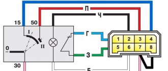
The diagram shows what happens in the cylinders when the marks are aligned
The light bulb is used to control the ignition timing, for which it must be connected with one wire to the “K” contact of the high-voltage coil, and with the second to the vehicle ground. You should know that at the same moment the piston of the first cylinder is also in the TDC position, only there the air-fuel mixture is not compressed, but exhaust gases are released after its combustion. This is why ignorant car enthusiasts often confuse the first cylinder with the fourth when installing the ignition.
Layout of marks on the timing cover
When the above actions occur simultaneously, a spark discharge occurs on the electrodes of the spark plug of the 4th cylinder, as evidenced by the flash of the connected light bulb. To achieve these conditions and set the ignition correctly, follow the instructions:
- Turn the crankshaft with a 36 mm wrench, aligning the notch on the pulley with the long notch on the timing cover.
- If at this moment the engine valve cover is removed, then it is better to navigate by the mark on the camshaft gear, placing it opposite the housing boss.
- Take the ignition distributor, remove the cover and turn its shaft to place the slider opposite the wire leading to cylinder No. 4 (there are cylinder number markings on the cover). Insert the distributor into the engine hole, holding the slider and housing in this position, and then secure it with a 13 mm wrench nut.
- Connect the light bulb wires and turn on the ignition by turning the key. Loosen the nut securing the distributor and slowly turn it by the housing until the lamp flashes, indicating the moment of sparking. Reattach the distributor.
- Turn off the ignition and make sure that the contacts inside the distributor are currently open. Take a 0.35 mm feeler gauge and check the gap between them, if necessary, adjust it by loosening the fastening screws with a screwdriver.
The marks must be aligned by turning the crankshaft with a wrench
Note. The instructions imply that before starting work the distributor was removed from the engine without aligning the marks.
The ignition is considered to be set correctly if, after installing the distributor cap and connecting the wires, you manage to start the engine, and then you need to adjust the timing. The non-contact system is installed in the same way, with the exception of checking the gap in the contact group due to its absence.
Instructions for replacing the timing chain in a VAZ 2107 car are presented here: https://vazweb.ru/desyatka/dvigatel/zamena-tsepi-grm-na-vaz-2107.html
The mark on the camshaft gear is aligned with the boss on the body
Important point. In most cases, the ignition is set without removing the valve cover, which is why the position of the mark on the gear is not visible. You have done everything according to the instructions, but the engine does not start. This means that a spark is supplied to the 4th cylinder during the exhaust stroke, and compression at this moment occurs in the first cylinder. The problem can be solved simply:
- remove the distributor cover;
- unscrew the nut securing it;
- pull the distributor out of the socket, turn the slider exactly 180° and insert the element back;
- Press the distributor skirt with the nut and install the cover.
Advice. If the engine does not start after these steps, but begins to show signs of life, then the problem lies not in the ignition setting, but in a malfunction of one of the system elements.
Photo instructions for setting up
Video about correct ignition installation
Checking the secondary windings of the module
First, disconnect the wire ends from it. If you have already done this, then place it exactly in front of you. Then install the device to the upper and lower right outputs and carefully monitor the indicators that the device will display in a second.
After this, we perform exactly the same actions with the upper and lower left exits. Naturally, the ohmmeter readings should change and ideally be at least 7 ohms.
If at least one coil does not meet the standards, then in order to avoid unforeseen situations with your VAZ 2107, we recommend replacing the entire module.
How to remove the coil
If your fears are confirmed, and the coil really needs to be replaced, then installing a new one will not be difficult.
To do this, first remove the air filter housing, then the negative wire terminal from the battery and disconnect the high-voltage wires from the module. Having removed the wires located there from the module cover, unscrew the three nuts that secure it and disconnect it from the bracket.
That's all. Even a novice VAZ 2107 driver can perform such simple manipulations. If you already have a new part, then immediately after removing the coil you can install it. To do this, you need to perform all the steps we previously described in reverse order.
If it happens that you suddenly forgot how the high-voltage wires were originally located, then thanks to one little hint from a caring manufacturer, you won’t have to fiddle around for long. The secret is that on the module itself the numbers of the cylinders to which the wires must be connected are indicated.
Setting the ignition
Another important problem among VAZ 2107 owners with an injector system is how to accurately set the ignition.
As you know, in such models, all engine control is carried out electronically, so for such work you will need a computer, installation of a special program on it for the engine of an injection car, a tester, as well as keys and screwdrivers.
First of all, turn on the ignition and ground to make sure the electric pump is working. If it does not work, then check the relay that controls it.
Is the fault light flashing? Connect your personal laptop with a special program to the car’s on-board computer to try to determine the cause using the available data.
If the engine is working properly, you should start it and check the throttle device: throttle position sensor, throttle opening level (no more than 1%) and passing wires. Use a tester to measure the voltage of the sensor (it should not exceed 0.55 volts) and the on-board network (its voltage should exceed 12 volts).
Perform the same actions again, but with the gas pedal pressed all the way. Now all readings should change as the sensor voltage is normally around 4-4.5 volts and the throttle opening is hovering around 90%. Adjust the throttle to full opening and turn off the additional air flow, and then start the engine and lock the throttle at half opening. Now you should adjust the throttle to completely close the hole.
As you can see, there is nothing difficult either in installing the coil yourself or in setting the ignition on this car model. Now you can decide for yourself whether to contact specialists or not. Remember that by performing small checks and minor repairs on your VAZ 2107 on time, you will always be confident in the reliability of your “iron horse”.
How to Check the Ignition Module of a VAZ 2107 Injector
The ignition module is a mechanism that is very difficult to detect. Usually, obstacles begin to clear when it becomes clear that something is wrong with the car. If your VAZ 2107 does not start for the first time, you will not be able to turn on the ignition, and uneven engine operation will begin to bother you - it’s time to carry out proper testing. Let us recall that the engine ignition module “Injector” is a system that, using coils, supplies electronic energy to create a spark and start the car.
If you decide to check if the ignition module is working and if any coil is working, you will need to use a special device called a multimeter or in other words an ohmmeter. It will show the ignition module voltage and help you find the location of the leakage current in the circuit.
For your convenience, it is better to put the module before the process - it will be easier for you to do such a thorough job, and you will not get tired.
Disconnect the module from the tips and connect one output of the device to the central contact with the coil, and the second to ground. If the device screen displays “infinity”, this means that there is no short circuit, in other words, everything is fine. It is worth noting that if the characteristics on the monitor did not change when the circuit was installed (and, for example, number one remained), then this is infinity.
Now we will check whether the primary ignition circuit is closed.
To do this, install a multimeter on the left and right contacts, which are responsible for the ignition function. In this case, the ohmmeter should change its readings. Otherwise, not only the coil will change, but the entire device. Please note that the rating is 3-3.5 ohms.
Checking for spark
When the engine of a fuel-injected VAZ 2107 refuses to start, it is simply wrong to blame the spark plugs for this malfunction. First you need to make sure that this is the problem, and only after that find out the reasons for the malfunction of the ignition system. Not all drivers know how to check the spark on a fuel-injected car. But this is not a difficult procedure, which will 100% allow you to find out where to look for the reason for the inability to start the engine.
Checking for a spark on the spark plugs is done in the following ways:
- The easiest way to check is by mass. It can be implemented by performing the following actions - turn off the ignition, unscrew each spark plug one by one, and connect it to the spark plug and place it on the metal part of the engine. In this case, one person tries to start the engine, and the second watches for the presence of a spark.
- There is another method, which involves using a special candle tester. Its principle is based on the fact that the spark plug must be unscrewed from the cylinder and connected to the contacts of the tester. The spark must come from the device itself.
A weak spark or its absence indicates that the reason the engine does not start lies precisely in the spark-creating device. If there is a weak spark, the engine may start, but it will be unstable. Unstable operation also negatively affects its operational life. The absence of a spark does not mean that the cause of the malfunction is in the spark plug. The cause may also be a malfunction of the vehicle's ignition system.
What are the causes of problems with spark formation?
It is easier to identify the reasons for the lack of spark formation on a carburetor engine than on an injector. This is due to the design features and differences between these systems. There is a list of reasons for problematic sparking on injection cars, in particular on the VAZ 2107. Some of them are similar to carburetor systems. These reasons are the following factors:
- Filling spark plugs with fuel. Such a malfunction can be identified visually after unscrewing the device from the cylinder. In this case, the contact part will be wet.
- Failure of the spark plug, which is also detected by visual inspection of the contact part. The presence of black or white carbon deposits indicates some engine malfunction. If the carbon deposits on the spark plug are red or pink, this indicates that the fuel used contains a large amount of additives.
- Breakdown of high-voltage wires. Their malfunction can be determined visually, but the absence of mechanical defects does not always indicate their unsuitability. Over time, the quality of insulation deteriorates, and the resistance in the wires also increases, so it is recommended to replace high-voltage wires every 5 years.
- Malfunction of electronics, in particular the ECU. The reason why the spark plugs are flooded may be a faulty lambda probe sensor.
- Clogged injector nozzles. For this reason, the injector will also not work correctly, since there will be a lot of fuel mixture in the combustion chamber, and it will interfere with the normal operation of the engine.
- Malfunction of such elements of the ignition system as the switch, ignition coil, crankshaft sensor. If these parts fail, there will be no spark at all.
If there is no spark on all spark plugs or it is very weak, then you should check the serviceability of other devices. If there is no spark on only one part, then there is a high probability that it is faulty. You can verify this by screwing in a known good spark plug instead of a faulty one. If such experience confirms that it is the spark plug that is faulty, then it is advisable to replace all 4 elements.
This is interesting! To identify the exact reason why there is no spark on the VAZ 2107 injection engine, it is recommended to conduct computer diagnostics. If error code P03XX is displayed on the on-board computer, this indicates a malfunction in the ignition system.
Bringing the car back to life
Often, restoring engine performance due to a lack of spark in the spark plug on a VAZ 2107 is not particularly difficult. Usually this does not require digging deep, and it is enough to replace the sparking devices or armored wires to restore stable engine operation. You can resort to computer diagnostics only if a visual examination does not give a positive result. Depending on what the visual or computer diagnostics showed, it is necessary to take appropriate measures to bring the car back to life.
Many people simply do not pay enough attention to the timely replacement of spark plugs and armored wires. This ultimately leads to adverse consequences. Injection VAZ 2107 cars are more sensitive to various failures, therefore, if there are any, errors and engine inoperability occur. To determine why the engine on the seven does not start, it is recommended to check the following components:
- Candles and armored wires.
- Ignition module. To check it, you must install a known-good unit.
- Make sure that the control unit transistors are in good condition. It happens that the transistors burn out, which leads to the disappearance of the spark. Computer diagnostics will help you find out if transistors are faulty.
- Check the flow of the fuel mixture into the cylinders. If the fuel pump does not pump when the ignition is turned on, the engine will not start due to lack of fuel supply.
- Check the supply voltage at the injectors, for which you will need a multimeter.
- Check the pressure in the fuel rail using a pressure gauge.
Sevens with injection engines are very popular, but problems that arise with the ignition and fuel supply systems are more difficult than with carburetor models. You shouldn’t rush to go to a car service center, since it’s quite possible to fix this type of breakdown yourself.