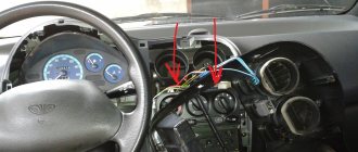
Contactless ignition system gas 53 circuit
First of all, let's get acquainted with the ignition system of the GAZ-3307 truck. The ignition system of the GAZ-3307 is battery-based, contactless transistor with a voltage in the primary circuit of 12V, consists of electric current sources, an ignition coil, an additional resistor (if I’m not mistaken, where since 2000 they have been produced without an additional resistor), a switch, an ignition distributor, spark plugs, plug tips, ignition switch and low and high voltage wires.
Technical characteristics of the ignition system of GAZ-3307 (GAZ 53) cars
Ignition order of GAZ-3307 1 - 5 - 4 - 2-6 - 3 -7 - 8 Type of ignition distributor (distributor) - 24.3706 Distributor shaft rotation speed per 1 min with uninterrupted spark formation when working with a B116 ignition coil on a three-electrode spark gap at spark gap 7 mm, min-1 - 20 - 2300 Direction of rotation of the ignition distributor roller (distributor) GAZ-3307 - clockwise Ignition coil GAZ-3307 - B116 Spark plugs - A11 Spark gap size in spark plugs, mm - 0.8 - 0.95 Additional resistor - 14.3729 Switch - 131.3734 or 13.3734 Spark plug tip - 35.3707200
Diagram of the GAZ-3307 ignition system
And so, as I already said in our time, the ignition system of the GAZ-3307 truck has undergone minor changes.
As I already wrote, this happened after 2000, this is approximately what I am saying. I can’t say for sure, I’m afraid I’ll make a mistake, but I didn’t bother googling and searching for it; I just don’t have time for it and it’s not particularly interesting. If you are interested, look for it and then share it with me. You can leave a comment.
This applies to transistor switch brands 13.3734 and 131.3734
You can see the difference is just one number, that is, it was 13.3734 before 2000, but they began to produce the GAZ-3307 after 2000 with a switch of 131.3734. And so there is only one number and this is one number, that is, as you noticed, number 1 removes the additional resistor from the GAZ-3307 ignition system - 14.3729.
That is, simply put, the function of the additional resistor is 14.3729. built into the transistor switch 131.3734.
I want to warn you, someone may say “yes, I put brand 13.3734 instead of brand 131.3734 and why doesn’t the machine work?” I agree with him.
GAZ-3307 will of course work and go normally, but not far. Why, you ask, of course, and you will be right, you need to find out why ? Yes, because your ignition coil (bobbin) will simply burn out.
Why this will happen : The ignition coil, GAZ-3307 (B 116) is a transformer, on the iron core of which the secondary winding is wound, and on top of it is the primary winding. The core with windings is installed in a sealed steel case filled with oil and closed with a high-voltage plastic cover.
Operating temperature from -50° C to +80° C. Resistance value at a temperature of 25° C: primary winding (0.65+0.07) Ohm, secondary winding (18+1.8) kOhm.
Developed secondary voltage 18 kV max. Supply voltage 12 V. Weight 0.95 kg. During operation, the B-116 ignition coil is supplied with reduced voltage through an additional resistor-14.3729 . The resistor heats up during operation, this is normal. The resistor, when the starter is turned on (when starting the engine), is bypassed and the coil is supplied with full voltage (more precisely, the on-board voltage supplied by the starter), this makes starting easier.
the additional resistor 14.3729 takes up “work” again . And now give yourself this picture of a GAZ-3307, well, let’s say after the year 2000, there is, of course, ignition without an additional resistor - 14.3729 and an ignition coil B-116 and a transistor switch 131.3734, and you took and installed a transistor switch 13.3734, and what next GAZ-3307 Of course, it will start; moreover, it will drive normally (as I already stated above), but the coil will not burn out very far. That is, there is no one to lower the on-board voltage for the ignition coil.
And as we already know, the B-116 ignition coil is powered by a reduced voltage through an additional resistor-14.3729 or with an added voltage reduction function in a transistor switch brand 131.3734.
And as a result, the B-116 ignition coil will simply burn out.
I still cannot help but note this moment. There is also a B-114 ignition
As you noticed, it looks no different from the B-116 (some people use it), it also fits the GAZ 3307, but I personally do not advise you to use it. GAZ-3307 will of course work (I checked it myself; I had to drive home B-114 ignition the B-116 burned out). If you put it on and drive it, you may not feel the difference, but in the end it will affect fuel consumption (increase )and of course the car’s traction (decreased), the engine will run unstably. Simply, the B-114 ignition coil is designed for GAZ-53 with a contact-transistor ignition system
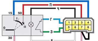
Connection diagram for the new ignition system. Switch 131.3734.
1. Candles; 2. Anti-interference resistance; 3. Distributor; 4. Switch; 5. Ignition coil; 6. Generator; 7. Fuse; 8. Battery; 9. Ignition switch.
Connection diagram for switch 131.3734 as part of the ignition system:
Wiring diagram for the old-style ignition system. Switch 13.3734.
1. Distributor; 2. Switch; 3. Additional resistor (variator); 4. Ignition coil.
You can familiarize yourself with the contact-transistor ignition system in this article:
Contact-transistor ignition system of GAZ-53.
And so, friends, you and I, I think, have finished familiarizing ourselves with the ignition system of the GAZ-3307 (GAZ-53) truck. If you suddenly have any questions, you can leave comments.
Now let's figure out what are the reasons for the lack of a spark.
If suddenly you haven’t found something, or you simply don’t have time to search, then I recommend reading the articles in the “ GAS Repair ” categories.
I am sure you will find the answer to your question, and if not, write in the comments the question you are interested in, I will definitely answer.
Operation of the generator circuit 5101.3701
Initial generator excitation
UAZ contact ignition system, composition and general structure, diagrams of the contact ignition system. procedure for installing the ignition on a UAZ car; wiring diagram for electronic ignition on a UAZ.
When starting, the initial excitation comes from the battery. Then, when the generator starts working, it itself transfers part of its current to excitation.
When the ignition is turned on (VPS), a plus comes to terminal B of the generator, which goes to point B of the regulator via the yellow wire, and the output transistor of the voltage regulator opens. The excitation current begins to flow through the circuit - from point 151, through the 10th fuse, through the light bulb, to point D of the generator, then along the green wire to the brush assembly of the generator, through the brushes into the excitation winding, then through the open transistor of the regulator to ground. To power the regulator, the plus must be at its point B. This plus goes from the brush assembly via the orange wire to the additional rectifier, and from there via the red wire to point B of the regulator. The additional rectifier itself does not work yet. The current flowing in this circuit lights up a light bulb, which confirms that the excitation circuit is intact and the generator is ready for operation. A small current from this circuit magnetizes the rotor; when the rotor begins to rotate, its magnetic poles, replacing each other, create a changing magnetic field, which excites an EMF in the generator winding. This is how the generator gets excited and starts working.
The light bulb, with its resistance, limits the initial excitation current to 100 mA. This current is sufficient to excite the generator. The light is on, indicating that the excitation circuit is intact, the excitation current is flowing and the generator is ready for operation.
Excitation of generator 5101 through an additional rectifier
This generator uses a circuit with additional diodes to power the excitation winding. An additional rectifier consisting of three small diodes is provided in the diode bridge of the generator. For these generators, a diode bridge of the figure-eight generator 372.3701 is used, a brand of diode bridge BPV 56-65-02 of the old type with two wires.
Figure-of-eight diode bridge
The generator circuit with additional diodes allows you to receive the excitation current not from the output of the generator, but from the output of additional diodes. This point is not connected to the battery positive and therefore accidental discharge of the battery through the generator excitation winding is excluded. The excitation current in such a circuit flows only inside the generator and does not use external circuits and the ignition switch (except for the initial excitation). The reliability of such a scheme is much higher than schemes without additional ones. diodes.
When the generator is running, the excitation current no longer comes from the battery, but from the generator through an additional rectifier. The magnitude of this current is determined by the resistance of the field winding and is (3-5 A, rotor winding resistance is approximately 6 Ohms), such a current is necessary to obtain the full power of the generator. The output from the additional rectifier via the red wire provides power to the voltage regulator circuit.
The light bulb is a convenient indicator that allows you to monitor the operation of the generator.
The light is on, which means the battery is being discharged.
Thus, if after starting the engine the light goes out, then everything is fine and the generator is working.
Generator assembly 5101.3701. How to arrange the wires correctly?
how to connect the generator wires on a GAZ 3309
The generator brush assembly is similar to the generator brush assembly from the Zhiguli G221, but it has three connection points and both brushes are isolated from ground, so do not forget to put an insulating washer under the brush assembly mounting screw.
A simpler connection procedure is also possible without disrupting the circuit.
VESKO-TRANS.RU
AutoNews / Reviews / Tests
How to set the ignition to gas 53
Installation of the ignition system on GAZ-53
GAZ-53. one of the few trucks that our homeland can be proud of. All GAZ-53 systems meet all the requirements for trucks intended for use on all types of roads. The only system that may interfere with some obstacles. This is the car's ignition.
Dump truck based on GAZ 53
Ignition system GAZ 53
GAZ-53 has a non-contact ignition system for transistors, the primary circuit of which produces a voltage of 12 volts. The ignition system is a battery consisting of electronic sources that can act as a battery, ignition coils , switch, distribution switch and other electrical equipment, gas 53, which in most cases creates interference as it needs to be adjusted, spark plugs, additional resistor, low level and ignition switch high voltage .
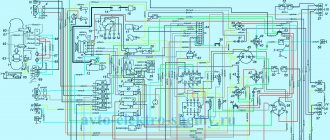
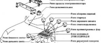
The drawing shows a complete diagram of the GAZ-53 ignition system
The ignition system is one of the most important systems in a car, as it depends on the proper operation of the engine and the fuel consumption of the entire car. To suppress radio waves generated by high-voltage wires and spark plug tips, the former have a distributed resistance, and the latter have suppression resistors.
The ignition system has a B 116 brand coil whose purpose is to convert low voltage current into high voltage voltage.
Useful tips
The ignition system of the GAZ 53 vehicle requires periodic inspection. It is necessary to check the quality of fit of high-voltage wires into the sockets of the coil and distributor. If there is a weakening of the contact, then you need to unbend the wire connectors and insert them into the sockets until they stop. A breakdown of the ignition coil is most likely if it is covered with a layer of dust, dirt or in water. Therefore, this should be avoided if possible. Leaving the GAZ 53 with the ignition on and the engine not running can lead to a breakdown of the coil.
The fact is that there is always voltage in the primary winding when the ignition is on and the engine is not running, because the breaker sensor does not work. When purchasing new spark plugs, it is advisable to install those recommended by the manufacturer, having first checked the gap between the electrodes. Adjust it if necessary. Replacing elements with new ones with different markings may lead to failure of other components of the system. It is necessary to periodically lubricate the distributor shaft through the existing oiler.
Correct operation and repair of the ignition switch
The operation of the ignition switch has several subtleties that especially need to be taken into account in older cars. It is important to remember the following:
- The key must be turned smoothly and without jerking, and the key must not jam or slip (if this happens, the lock must be checked and repaired);
- Do not turn the key to the “Stater” position when the engine is running, as this may lead to damage to the starter. Many modern locks have a function to block the key from turning when the engine is running;
- Do not leave the ignition key in the “ON” position when the engine is stopped, as this will discharge the battery;
- To lock the steering wheel, you must first remove the key and then turn the steering wheel in one direction or another until it stops.
Some cars have other features of the ignition switch; they must be indicated in the operating instructions.
The ignition switch is one of the most reliable parts of a car, but over time it can also fail. The most common problems encountered are jamming of the cylinder, wear of the cylinder, wear and corrosion of contacts, or mechanical damage to the contact unit. If the cylinder fails, the lock is replaced completely; if the contact unit breaks, only it can be replaced without touching the cylinder. However, today, in case of any malfunction, the lock is most often replaced completely, since this is easier and cheaper than disassembling and repairing the old lock.
It should be noted that some problems can be solved without replacing the lock. For example, if the lock jams, especially on domestic cars, you can try treating the cylinder with graphite lubricant. And damage to contacts or conductors in a contact assembly can be repaired by soldering or replacing these parts.
In general, the ignition switch usually does not cause problems for the car owner; in good condition, it provides easy operation and protection against theft, and lasts for many years.
If the engine does not start, but there is a spark on the center wire.
In this case, there may be a malfunction of the distributor slider, that is, its breakdown or burnout of the resistance due to radio interference.
To check the slider for breakdown, simply place a high-voltage wire from the coil onto the distributor above the slider and crank the engine with the starter. In this case, it is necessary to take precautions against electric shock; it is not fatal, but very unpleasant. If a spark jumps between the wire and the slider, the slider must be replaced. If the spark does not jump, then check the serviceability of the resistance installed in it.
There may be other malfunctions in the ignition system, but with them the engine will start, but it will run unstably or stall.
Electrical diagram
First of all, we note that any electrical circuit of a car, including one like the GAZ 53, is equipped with the following elements:
- GPT – alternating current generator;
- KTS – contact-transistor ignition system;
- start heater;
- wiring of different voltages connecting all elements into a single circuit.
Attention. The electrical circuit of the GAZ-53 truck is not designed for non-standard loads. Therefore, it is forbidden to start the engine if the cable running from the generator to the regulator is damaged or if it “sparks”.
Ignition system
Let's first consider the ignition system. It is known that it is battery operated, with a circuit voltage of 12 V.
It also consists of the following components:
- switch;
- sources supplying current;
- coils;
- resistor (additional);
- ignition distributor (distributor);
- candles with their tips;
- ignition switch;
- wiring.
Note that the smooth operation of the engine directly depends on the normal functioning of the ignition system. To avoid radio interference caused by the ignition system, the wires are equipped with a resistance distributor (this mainly applies to HV wires), and the tips of the spark plugs are equipped with suppression resistors. (See also the article Features of the GAZ wiring diagram.)
Let us now consider each element of the ignition system separately and find out how it functions.
- Spark plugs for GAZ 53 must have a factory gap of 0.85 mm. They must have a nichrome electrode - A11, A11-1, A10-H and others are suitable. The ignition order can be seen in the photo below.
- The ignition distributor is used in this car so that the rotation speed of its roller is one minute with uninterrupted sparking. Functions simultaneously with the ignition coil. The roller must rotate clockwise.
- Ignition coil - B114-B or B116 (more advanced). Generates high voltage pulses in the ignition system of a GAZ 53 car. It has a rated voltage of 12V and a secondary voltage of 17kV.
- The ignition switch amplifies the signal from the distributor sensor and the ignition coil. (See also the article Gazelle wiring diagram: how to install it yourself.)
Note. To connect all of the above parts and assemblies of the vehicle's electrical equipment into a single circuit, low voltage wires are used. They must be protected with polyvinyl chloride insulation.
Wiring
The basic rules that are followed when working with wiring are as follows.
- Careful attention is always paid to the wiring of the GAZ 53, which may be subject to various influences. If the insulation of any wire is broken, its metal component may touch the car body, thereby causing a short circuit. There is no need to say what this leads to (burning of insulation, fire, etc.).
- It is important to take into account the fact that the wires, no matter how well they are insulated, are always subject to mechanical stress during vehicle operation. In particular, it is possible for the wiring to rub against sharp edges of car parts, excessive sagging, etc.
- In addition, special attention should be paid to the cleanliness and tightness of connecting the wires to the terminals. Care must be taken to ensure that mixtures such as gasoline or oil, which can destroy the insulation and shorten the service life of the wires, do not come into contact with the surface of the wires.
- It is imperative to check the serviceability of the jumpers located between the engine, frame and cab of the GAZ 53.
The wiring of a GAZ-53 car is such an important component that its simple modernization leads to tangible positive changes in the operation of the engine. (See also the article Features of the Gazelle Business wiring diagram.)
Design of the GAZ 53 ignition system
The GAZ-53 is equipped with a non-contact transistor ignition system, the primary circuit of which produces a voltage of 12 volts. The ignition system is considered battery-based, consisting of sources of electric current, which can be a battery, ignition coil, switch, sensor-distributor, and other electrical equipment gas 53, which most often causes problems, since it needs to be adjusted, spark plugs with tips, additional resistor, ignition switch, low and high voltage wires.
The drawing shows a complete diagram of the GAZ-53 ignition system
The ignition system is one of the most important systems in a car, since the operation of the engine, as well as the fuel consumption of the entire car, depends on its proper operation. To suppress radio interference created by high voltage wires and spark plug tips, distributed resistance is installed on the former, and suppression resistors are installed on the latter.
The ignition system contains a B 116 brand coil, the purpose of which is to convert low voltage current to high voltage.
In turn, the coil consists of a transformer in which an iron core is mounted. The primary winding is wound on top of this core, and the secondary winding is below it. The transformer itself is a steel case, which is hermetically sealed; oil is poured inside it along with the core.
To maintain this transformer, a plastic cover is provided that can withstand high voltage.
Device
The ignition system of the GAZ 53 car is currently contactless. Having studied the device and principle of operation, you can simultaneously master troubleshooting skills. This is especially necessary for those who operate GAZ 53. After all, it often happens that there are no good specialists nearby who would help in solving problems that arise. In addition, you will have to pay for their services. The quality of the work done can sometimes be determined after some time. A malfunction that occurs unexpectedly and at the wrong time will create trouble.
System elements
The ignition system of the GAZ 53 car consists of several elements, each of which performs its own function. Knowing them, you can find and fix the problem much faster. The system consists of the following elements:
- Rechargeable battery;
- Switch;
- Spark plug;
- Sensor distributor;
- High-voltage and low-voltage wires;
- Ignition coil;
- Additional starter relay;
- Additional and noise suppression resistor;
- Current indicator;
- Egnition lock.
All constituent elements can be grouped depending on the tasks performed. In this case, they will be included in the appropriate groups. The ignition system of the GAZ 53 car will work correctly when the basic conditions are met:
- Comparison of the moment of spark occurrence and engine operation;
- Sufficient spark power;
- No gaps in sparking.
To supply a spark in a timely manner, you need to carefully correlate the engine operating cycles and the appearance of voltage on the spark plug electrodes. The required spark power, in turn, depends on the voltage, the gaps between the electrodes of the spark plug and the serviceability of the circuit. The lack of a spark leads to a decrease in power and an increase in fuel consumption, so misfires are unacceptable.
A Timely Spark
Comparison of a certain stroke and voltage supply to the spark plugs is the task of the distribution sensor. The contactless ignition system of the GAZ 53 car can be equipped with a magnetoelectric or semiconductor sensor-distributor, which is located inside the distributor. The list of distributor elements includes:
- Sensor-distributor;
- Current carrying plate (runner);
- Centrifugal and vacuum regulator.
The GAZ 53 magnetoelectric sensor is a generator of alternating current pulses, the frequency of which depends on engine speed. This device has eight poles (according to the number of cylinders). During the rotation of the camshaft, and with it the sensor rotor, the poles of the permanent magnet sequentially pass through the poles of the stator winding. As a result of the changing magnetic flux, an induced emf is induced in the winding, which creates a control pulse for the commutator.
The centrifugal regulator rotates the sensor rotor relative to the stator, which, in turn, changes the ignition timing of the GAZ 53. This occurs when the engine crankshaft speed increases. The regulator weights, overcoming the force of the springs, turn the rotor. Thus, the effort must be certain, otherwise it will affect the operation of the GAZ 53.
The vacuum regulator rotates the stator relative to the rotor, changing the angle. It operates depending on the load and engine speed.
Power and spark quality
It's no secret that a good spark is the key to high-quality ignition of a combustible mixture. The ignition system of a GAZ 53 car will have a good spark if the following conditions exist:
- The gap between the spark plug electrodes is correctly adjusted;
- Serviceable ignition coil;
- The desired shape of the commutator pulses;
- Good quality high voltage circuit.
If the gap between the spark plug electrodes is too small, ignition of the air-fuel mixture will be difficult. Because of this, a gap may occur not in sparking, but in ignition. The consequences are the same.
The serviceability of the ignition coil is manifested in its ability to induce the required voltage without interruptions (skips). As a rule, a faulty coil makes itself known by a characteristic decrease in the quality of operation of all eight cylinders. If it is determined that the coil is faulty, then it must be replaced with one of the same type, with the same markings. This GAZ 53 part consists of two windings: primary and secondary. The latter contains many more turns than the first. The windings are wound one on top of the other on a magnetic core. The entire structure is housed in a sealed housing filled with plastic. The malfunction of this part is associated with a short circuit, which can be interturn and to the housing.
Installation of distributor Gas 53
If the distributor drive is installed correctly, then there are no difficulties with installing the distributor. There is a groove in the distributor drive shaft. Which is offset relative to the axis of rotation. Accordingly, on the distributor shaft. Which connects to the distributor drive shaft. There is a ledge. Which is also offset relative to the shaft axis. With the correct connection of the groove and the protrusion, the required position of the distributor is achieved. If the car is new. It will not be possible to confuse the position of the distributor relative to the protrusion. The distributor will not sit in its seat. until the groove and the lip line up.
But if the motor has been running for a long time. Shafts and connecting surfaces are worn. The groove and the protrusion may not connect correctly. The distributor will rotate 180 degrees. From the normal position.
Homemade options for using the internal combustion engine ZMZ 53
Due to the unpretentiousness of engines of the ZMZ 53 series, their availability and relatively low cost, many “homemade” ones often try to “introduce” internal combustion engines into other brands of cars. For example, similar units have already been installed on Gazelle.
Despite the rather impressive dimensions, the “Gazonov” engines have a relatively light weight (230-270 kg), and the engine still fits under the Gazelle’s hood without loading the car very much. These engines are also installed in UAZ vehicles with appropriate modifications (the radiator is changed, the internal combustion engine mounts are reworked, etc.)
An example of a homemade tractor using a ZMZ 53 engine
Possible malfunctions of the SZ: signs and causes
Malfunctions in the SZ affect the power of the power unit, it decreases, and economical fuel consumption.
The following reasons can be cited for the unstable operation of the SZ on the GAZ-53:
- Switch overheating or failure. When the switch overheats, the spark disappears and the engine will not start. It becomes possible to start the engine only after it has cooled down and a spark appears. The coil is also susceptible to overheating.
- Breakdown in high-voltage wires. This happens if the wire is not held tightly enough in the distributor cover: the motor will operate unstably and intermittently. The breakdown of the wires is noticeable in the dark - blue sparks jump.
- The cover on the breaker-distributor burned out. A malfunction can be detected by visual inspection. It is possible to burn in the place where the corner with the spring is installed. The cover must be free of defects and must not have potholes or cracks.
- The contacts of the distributor slider may burn out.
- Breakdown of candles.
If the diaphragm makes gaps on the vacuum regulator of the distributor, then a drop in engine power is observed. Moreover, if you accelerate sharply, the power unit will choke and may overheat. The distributor rarely fails; most often the cause of its failure is wear due to the exhausted resource.
Instructions for setting up the ignition
The cause of engine overheating and loss of power may be late ignition. This may manifest itself as popping noises in the intake manifold. Therefore, you need to know how to install the ignition correctly (the author of the video is Nail Poroshin).
Installation is carried out according to the marks as follows:
- First, you need to set the piston on the first cylinder to TDC and align the installation indicator mark with the mark on the crankshaft pulley.
- Next, the crankshaft must be turned counterclockwise until the marks 9 on the pointer coincide with the marks on its pulley.
- Then you need to loosen the bolt on the top plate of the corrector, thanks to which it is attached to the breaker.
- Next, you need to connect one control wire to the car body (ground) and the second to the breaker terminal. After turning on the ignition, the breaker should be turned slowly until the control lights up. This indicates that the contacts have begun to open.
- Now you need to tighten the breaker mounting bolt and install the cover and rotor. In the area opposite to the one where the rotor plate was installed, you need to connect the high-voltage wire to the spark plug on the 1st cylinder. The remaining wires are connected to the cylinder spark plugs, according to the order in which they work: 1-5-4-2-6-3-7-8.
It is necessary to set the ignition timing of the GAZ-53 accurately, since with deviations the engine power decreases and fuel consumption increases. In addition, burnout of valves, pistons, breakdowns in the cylinder head gasket and other problems associated with detonation are possible.
Therefore, the final adjustment is performed with the engine running, which warms up to a coolant temperature in the range of 80 - 90 degrees. With the engine running at idle speed, you need to loosen the fasteners of the distributor with a 10mm wrench so that it can be turned. After slightly turning the distributor counterclockwise, tighten the fastening bolt.
Pressing on the gas is how the power unit works. If you hear a “ringing of fingers,” that is, detonation occurs, turn the distributor clockwise in the opposite direction. Through trial and error we set the desired advance angle.
Sometimes the distributor is pushed to the extreme position, but the adjustment is not enough. In this case, you need to check the position of the distributor drive relative to the engine.
A check is performed with the engine not running:
- First, marks are placed on the front crankshaft pulley. They must match on the 1st and 6th cylinders. To avoid making a mistake, it is better to remove the valve covers from the first 4 cylinders and check the valves. If the valve marks are in the correct position, the valves in the 1st cylinder will be free.
- Having removed the distributor, we inspect how the drive is installed. If it is located parallel to the motor, then it needs to be replaced or repaired; adjustment, in this case, will not help.
- If the position of the drive is incorrect, you need to unscrew the fastening nut and remove the part.
- After the drive is completely installed in its place, you need to check that the groove for the distributor runs parallel to the internal combustion engine (in the direction of travel of the car), and a small section of the bushing on the distributor faces the 4th and 8th cylinders (towards the driver) . By experience, you need to achieve the correct position of the distributor drive.
Main elements of the system
To know how to properly adjust and configure the system, we recommend that you first familiarize yourself with the device. GAZ-53 trucks are equipped with contactless SZ.
Such a BSZ is battery-powered, since it contains current sources, in particular, we are talking about:
- battery;
- the coil itself;
- switching device;
- breaker-distributor;
- candles;
- resistor element;
- switch SZ.
Tuned truck GAZ-53
Any SZ of a GAZ truck includes two circuits: high and low voltage.
The main components of the low-voltage network are:
- 12 volt battery.
- Battery cables with terminals. These cables are multi-core and have a large cross-section.
- Directly the lock, which performs the function of supplying power to the circuit.
- The contactless circuit for GAZ is equipped with an ignition distributor breaker device mounted in the distributor. If the system is contact, then the function of this component is performed by the distributor pulley, as well as contacts. In addition, a Hall sensor is sometimes installed instead of a breaker.
- A switch designed to ensure stable operation of the power unit.
- Resistance designed to ensure normal engine starting and unload the work of the GAZ ignition coil when the power unit operates at high speeds. Thanks to this component, the coil cannot overheat.
- Primary winding.
As for the secondary section, it includes the following components:
- secondary winding;
- distribution element, which includes a pulley, a cover, and a runner;
- high-voltage wires transmitting a signal to the spark plugs;
- candles.
When the lock is activated, a magnetic field begins to form in the breaker design in the primary section. When the distributor shaft rotates, the current in this section of the circuit is interrupted, and accordingly, the formed field disappears. At this time, a signal begins to appear in the winding of the secondary circuit, which subsequently diverges through the cylinders.
Electrical circuit of the SZ vehicle GAZ-53