The brake system is one of the key components of the correct and safe operation of a car. Any malfunction in the brakes can result in a problem or tragedy for all road users. To avoid problems while driving, it is necessary to constantly monitor the condition of all parts of the system: discs and pads, and especially the brake fluid.
- Car brake system: what does a motorist need to know?
- Why does the brake system need to be bled?
- Air in the system: how does it manifest itself and how to get rid of it?
- The necessary set of tools for work
- General rules for bleeding brakes
- Procedure
- Differences and specifics of bleeding brakes with ABS
- Practical tips and nuances when bleeding brakes
Car brake system: what does a motorist need to know?
Before you get behind the wheel or get a driver's license, in addition to the rules of the road, you need to study all the internal systems of the car. First of all, the safety of the driver and passengers depends on this.
Serviceable brakes are a guarantee of a calm and confident ride on the road. To understand all possible situations or problems with the braking system, you need to understand how it works. On most cars, the braking process involves:
- brake discs (in some cases drums);
- pads
- brake fluid.
Each component plays a separate role in the process of mechanical deceleration of the car. When you press the pedal, a piston moves in the main brake cylinder, which releases the brake fluid. The latter, in turn, passes through the highways and actuates the brake cylinders on the wheels, and the pads are pressed against the drums or discs.
In modern cars, an anti-lock braking system (ABS) may be involved in the braking process. It allows you to avoid complete blocking of the vehicle's wheels during braking, thereby preventing the car from going into an uncontrolled skid.
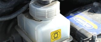
Additionally, an expansion tank for brake fluid and a vacuum booster are involved in the process. The latter serves to reduce pressure on the brake pedal.
Design and principle of operation of the main brake cylinder
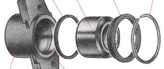
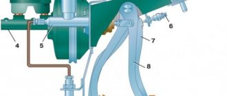
The brake master cylinder is attached to the clutch and brake pedal bracket. Pistons 3 and 4 (Fig. 136) drive different circuits. Both pistons occupy their initial position under the action of springs 7. The movement of the pistons under the action of springs is limited by screws 6. The tightness of the pistons in the cylinder is ensured by four sealing rings 5. The cylinder body 2 is closed at the front with a plug 1.
In the initial position of the pistons in the cylinder, the spacer rings 9 rest against the screws 6. In this case, the sealing rings 5 move away from the end surface of the piston grooves and, through the resulting gaps, the working cavities of the cylinder are filled with liquid from the tank.
When you press the pedal, the pusher moves piston 4 forward (to the left). The spacer ring 9 ceases to put pressure on the sealing ring 5, and it, pressing under the action of the spring 8 against the end of the piston groove, separates the cavity of the tank from the cavity of the cylinder. This ends the free play of the piston, which on the brake pedal is 3-5 mm.
With further movement of the piston 4, the fluid pressure in the drive cavity of the brake circuit of the front wheels increases and under its action the piston 3 of the drive of the other circuit moves. If the circuits are working properly, the pressure in both working cavities of the cylinder will increase equally.
Why does the brake system need to be bled?
The main reason for the need to bleed the brakes is the presence of air in the system. The entry of even small bubbles disrupts the operation of the brakes. Due to the uneven distribution of fluid, the compression process of the brake pads works asynchronously. If the intensity of the brakes on each wheel is different, the braking process becomes unpredictable (to varying degrees) and the driver may lose control at an unexpected moment.
It is worth noting that bleeding the system is, for the most part, a mandatory procedure after replacing the brake fluid.
Knowing when it's time to bleed the brakes is easy:
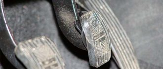
- An experienced driver who knows his car will immediately feel problems with the brake pedal. This may be an increase in the working stroke or excessive softness when pressed.
- Scheduled brake fluid replacement. Replacements must be made after reading the vehicle's operating manual.
- During a sudden stop, the car goes into a skid or a slight roll is felt in one direction or another.
On average, brake fluid is replaced every 2 years or every 50–60 thousand kilometers. However, during scheduled maintenance it is better to check the condition of the fluid using a special tester.
After any manipulations with the system, it is necessary to check the serviceability of the brakes and, in case of deficiencies in operation, carry out preventive maintenance to avoid problems while driving. The cause may be repair work on the master cylinder or vacuum booster.
Air in the system: how does it manifest itself and how to get rid of it?
It should be noted that, due to its structure, brake fluid is always in contact with air, thanks to the hole for the float rod - through the reservoir cap of the master cylinder. However, if the system depressurizes, you should not immediately blame the gas turbine cover, since the mechanism is designed in such a way that air cannot enter the working circuits.
However, to eliminate this source of the problem, it is worth pressing the brake pedal successively and leaving it pressed for several minutes. If the pedal slowly lowers, we can talk about a violation of the tightness of the system.
An additional cause of depressurization may be worn hoses or incorrect brake bleeding procedures. Already at the first action of air, while driving, the brake will work too softly and periodically fall into the floor, and the process of braking the vehicle will work unevenly and slowly.
The necessary set of tools for work
When you notice the first symptoms of a problem with the brakes, you need to decide whether it is possible to contact a service center. Our specialists have the necessary experience and skills to carry out work quickly and safely. Equipment plays a special role in solving the problem.
If in specialized places they use unique devices with universal adapters for any car, then when bleeding the brakes with your own hands, improvised means are sufficient. To carry out this, you need to acquire a set of appropriate keys, a container for brake fluid and several hoses. The diameter of the holes must completely match the bleeder fittings.
Replacing the front wheel brake cylinders
Remove the front brake caliper from the car and secure it in a vice. Remove the connecting tube of the working cylinders.
Using a screwdriver, press the spring-loaded clamp and use a soft metal drift to knock out the wheel cylinder from the caliper.
If the new cylinder does not have a lock, we replace it with the old one.
Install the cylinder in the reverse order of removal.
After installing the caliper on the car, bleed the brake system (see Replacing brake fluid and bleeding the brake system).
General rules for bleeding brakes
Before proceeding with actual bleeding, it is worth preparing clean brake fluid. Be sure to use only the liquid that was previously poured into the car.
If it is not possible to find out the exact brand of the substance, it is better to use the liquid that is provided in the car’s operating instructions.
It is better to pump the brakes with a partner. The main task of the assistant will be to consistently press the brake pedal at a signal, but the work of the chief mechanic will fall on your shoulders.
- The first step to successful and high-quality work will be a preliminary check of each circuit and drive unit for leaks.
- Most often, problems arise with the master brake cylinder - the most inaccessible portion of air is localized in it. It may need to be pumped several times by loosening the threaded valve.
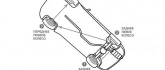
- Each car has its own unique brake bleeding sequence. You must read it in the vehicle's operating manual before starting the procedure. For most vehicles, the sequence starts with the rear wheels and is represented as "right rear wheel - left rear wheel - right front wheel - left front wheel".
Repair or replacement of the main brake cylinder
As for the main brake, the main malfunctions are the bypass of brake fluid between the circuits, sticking of the pistons and, as a result, incomplete release of the wheels, leakage of fluid through the rubber seals. Personally, I would recommend replacing the main brake cylinder , since in most cases the ease of bleeding the system depends on it, and the operation of the brakes will be trouble-free. If, in view of the budget, you decide to repair the main one, then I recommend that you buy a repair kit or similar, do not buy of dubious quality! Replacing the repair kit is carried out in the same way as replacing the repair kit on the clutch master cylinder.
By the way, during repairs, all parts of the brake master cylinder are cleaned of dirt, washed with clean brake fluid; under no circumstances should gasoline be used; all rubber bands are not resistant to gasoline.
If you decide to replace it with a new one, then everything is quite simple - remove the old one, install the new one.
Procedure
Success and high-quality pumping of the brake system lies in following the entire technology of action:
- The first step is to replace the fluid in the GTZ tank or check its quantity and, if necessary, top it up to the maximum level.
- For more comfortable work, it is necessary to clean all air release valves on each wheel from dirt, dust and deposits.
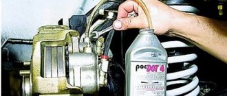
- According to the correct sequence provided in the instructions, it is necessary to unscrew the fitting plug on the desired wheel and attach the prepared hose over the valve.
- The second end of the tube is placed in a previously prepared container with brake fluid.
- The partner progressively presses the brake pedal from 3 to 5 times and at the last movement fixes the pedal in the pressed position.
- At this time, you need to unscrew the air valve halfway. After opening the valve, liquid along with air bubbles will begin to flow through the tube into the container. When the pressure of the liquid escaping into the container disappears, the valve can be screwed back firmly, and your partner can release the brake pedal.
- The process may have to be repeated several times on each node. The main thing is to maintain the wheel sequence and control the amount of fluid in the master cylinder reservoir.
After pumping is completed, you need to make sure that the fitting plugs are tight and that the brakes are operating. After the test, if successful, the brake operation will return to normal. If the driver still feels problems in operation, then perhaps attempts to bleed the brakes with their own hands were unsuccessful, or there is a problem with the wear of the pads or discs.
Differences and specifics of bleeding brakes with ABS
The anti-lock braking system allows you to control the vehicle's handling when braking. After pressing the pedal, the central control panel receives a response signal from sensors installed on the front and rear wheels. Thanks to the control system, the wheels slow down at the same speed as the car itself. In other words, thanks to ABS, the car cannot skid.
Regardless of the manufacturer, most devices have common characteristics:
- Electronic speed sensors on the hubs;
- Pressure controllers for main brake fluid lines;
- Electronic unit for signal processing.
Unlike most cars with simple braking systems, bleeding anti-lock brakes is difficult. For the procedure to be successful, it is necessary to familiarize yourself in detail with the theory of ABS operation. However, if the hydraulic accumulator, valves and pump are located nearby due to the design solution, the pumping technology will be very similar to the standard one.
Before starting work, in addition to standard tools, you must acquire a scanner to read information from the electronic unit. However, if the car has additional sensors, it is better to take the vehicle to a specialized salon. Any improper intervention calls into question the safety of road users.
Usually, for successful bleeding with the ABS system, it is enough to monitor the pressure in the hydraulic system. The standard value is 180 atm, but to work with the brakes it must be reduced - turn off the ignition and apply the brake 20 times. Only after this, some of the liquid will splash out and the pressure will drop significantly. After reducing the pressure, you can begin to turn off the ignition and disconnect the connectors and controllers on the GTZ tank for further manipulations.
Practical tips and nuances when bleeding brakes
Even if you follow all the points of the detailed instructions, you cannot be completely sure of the correctness of your actions and a reliable result. Experienced motorists know that the secrets of any independent manipulations in the car lie in the details.
While working with each wheel, it is worth tilting the car slightly in the appropriate direction. In this case, the air inside the system will rise up and flow faster to the threaded valve. Additionally, the process is activated by a slight vibration if you tap on the caliper.
In addition to the main method, you can bleed the brakes by gravity. It is necessary to unscrew the valves and add the necessary brake fluid to the supply tank in time. The procedure is quite lengthy and is only available to experienced car enthusiasts. Moreover, it is not suitable for vehicles equipped with return pressure control valves.
Bleeding the brakes, relying solely on your own experience, is fraught with breakdowns in the brake system. Incorrect actions can lead to large accumulations of air in the lines. Before you start working, you should familiarize yourself with the experiences of other people or watch training videos on the Internet:
Each vehicle system deserves special attention. Not only the proper operation of the vehicle, but also the safety of people depends on the correct operation of the internal mechanisms. Timely pumping of the brakes will ensure high-quality operation of the car in emergency situations.
Why is pumping needed?
Before starting work, you should determine the purpose for which the procedure is being carried out. It helps remove air from the hydraulic system. The reasons for the formation of air in the system include:
- any intervention (for example, during repairs) in the brake system; caliper overhaul;
- depressurization of the system during repairs;
- damage to hoses;
- replacing the brake fluid and reducing it to the minimum level in the brake cylinder;
- reuse of liquid.
Excess air can be detected when braking. Vehicles will be characterized by a sharp stop with increased braking. Pressing the brake pedal will be “soft” with increased travel. If you notice such “behavior” in your vehicle, you should urgently pump it - it is not safe to drive a car in this condition.
Bleeding involves removing air from hoses, calipers and tanks. Actually, it is necessary for the brakes to work smoothly. If there is air in the master brake cylinder, or it has been replaced, then it must be bled first.
Replacing the main brake cylinder VAZ 2101 - 2107
Even a novice car enthusiast can replace the master brake cylinder of a VAZ 2101. The whole process can be divided into several stages.
When performing the first stage, you should use a syringe or bulb to pump out the fluid from the reservoirs containing the brake fluid. Then you need to loosen the clamps on the rubber hoses, one of them connects the tanks to each other, and the other two go from the tanks to the master brake cylinder. After loosening the clamps, the hoses should be removed. When removing the hoses, the remaining brake fluid will flow out of them, and it will corrode the car’s paint, so after liquid gets into the engine compartment of the car, it is highly advisable to immediately wipe it off with a damp cloth. Let us remind you that the hose that goes from the tank closest to the fender goes into the hole closest to the cooling radiator, and the rubber hose that goes from the tank farthest from the left fender goes into the hole on the cylinder closest to the passenger compartment.
The second step in replacing the master brake cylinder is to unscrew the fittings that hold the metal tubes in the cylinder.
For this operation you will need a 10mm wrench, but it is more convenient to work with a special wrench for brake pipes. Since this key reduces the likelihood of “licking” the fitting nut.
Once the three metal tubes have already been unscrewed, you can begin to remove the brake cylinder. When unscrewing the nuts holding the master brake cylinder, you will be in the way of the brake fluid reservoirs, so it would be better to temporarily remove them, this will ensure a longer wrench stroke and accordingly speed up the work of removing the brake cylinder. To unscrew the nuts holding the cylinder you will need a 13 mm wrench; it is even better to use a wrench with a ratchet and a socket. After unscrewing the nuts, the cylinder is pulled out from the studs.
When installing a new brake cylinder, it is very important that the “pin” coming from the brake pedal rests against the recess in the brake cylinder. In order for the pin to rest against the groove described above, you should ask an assistant to press the brake pedal, or put a brick on the brake yourself (the pedal will be light and the pin will stick out easily), after the pin is visible, all that remains is to put on the new master cylinder onto the studs and guide the brake pedal pin into the groove of the cylinder.
Assembly is carried out in the reverse order: the brake cylinder holding nuts are screwed into place, the fittings of the metal tubes are screwed in (they should be screwed in with great effort, since when the master brake cylinder is in operation, high pressure is formed in the metal tubes), the tanks and rubber hoses are put on. It is quite possible to spend no more than an hour on replacing the master brake cylinder of a VAZ 2101, but after replacing the brake cylinder, you should bleed the car’s brake system.
Creator, Denis
LOOK AT THIS too)
Bleeding instructions
- I check the fluid level in the tank (it should be at the maximum level), top up if necessary.
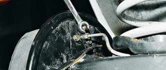
- I'm removing the plug. I insert a screwdriver between the piston and the plate to unlock the pressure regulator. I secure the plug so that air does not flow back. I clean the valve from dirt.
- I loosen the front nut of the fitting in the main brake cylinder with a metal tube. The main thing is not to completely unscrew the nut.
- I put unnecessary fabric or rags under the fitting - liquid will flow onto them. Alternatively, you can use a transparent bottle (any utensil) with liquid. Then the escaping air bubbles will be visible.
- I give the go-ahead to the assistant sitting in the cab, after which he smoothly presses the brake. When you press the pedal sharply and quickly, the brake fluid in the cylinder whips into foam, small air bubbles are formed, which will take a very long time to come to the surface. That is, it is practically impossible to expel such air.
- I unscrew the union nut until the fluid begins to leak. A little liquid comes out of the fitting along with bubbles that shouldn't be there. The pedal will drop a little.
- I tighten the nut and give the assistant the command to slowly release the pedal. If you do not release it smoothly, a vacuum will form in the cylinder.
- I repeat this sequence several times until air bubbles stop coming out. The time interval between procedures should be about 20 seconds. Since during this time the air bubbles will rise up, and when you press the pedal, they will immediately come out through the fitting. Only after the liquid begins to flow out is the GTZ considered to be pumped.
- I carry out the same procedure with the rear nut of the fitting.
I would also like to give some tips that it is advisable to follow for a successful procedure:
- It is important to ensure that the liquid in the tank does not run out. If the indicator approaches the minimum value, it should be topped up. Before you start pumping the liquid, there should be at least half of it.
- After removing air from the main brake cylinder, you should begin bleeding the working cylinders.
- You should use the brake fluid that is already poured into the system, or the one recommended by the manufacturer if you do not know which one is filled. Another option is possible: drain the one that is in the tank and pour a new one. Otherwise, serious problems may arise in the further operation of the system.
- You should also check to see if there are leaks anywhere.
- There is no need to start the engine.
- ABS, if installed on a car, should be disabled.
Symptoms of a faulty master cylinder
Problems that arise with the brakes while traveling are considered critical and must be corrected immediately. The culprit of the malfunction is often the main cylinder, installed in the engine compartment and rigidly connected to the pedal. To find out the cause of the breakdown and repair the unit yourself, you need to know the structure of the brake master cylinder (MBC) and its principle of operation. During the diagnostic process, it is necessary to distinguish and filter out problems with other elements of the system.
Repair of the main brake cylinder on a VAZ 2107
A serviceable brake system of a VAZ 2107 car is the key to the safety of both the driver and passengers. It is for this reason that special attention should be paid to it, and if the slightest sign of malfunction appears, repairs should be started immediately.
The main brake cylinder on the VAZ 2107 is one of the main elements of the car’s braking system. It may have two main faults. The first is expressed in the appearance of a fluid leak from the main brake, the second in a decrease in the efficiency of the system, which can only be determined after checking the workers. In most cases, both faults can be eliminated by simple repair of the main brake, which consists of replacing the sealing collars and boot. However, in some cases, only replacing the cylinder can solve the problem.
First, you need to disassemble the brake cylinder and determine whether it is advisable to repair it. To work you will need a minimum of tools:
- The key for 10 is normal;
- Special key for 10, for pipes;
- Key to 13;
- The screwdriver is flat.
The main cylinder is located in the engine compartment of the VAZ 2107, on the partition between the engine compartment and the passenger compartment. Before removing it, you need to disconnect the hose from the fluid reservoir and two tubes one by one:
- Before disconnecting the hose, it is recommended to remove the brake fluid from the reservoir to avoid spilling it. The procedure is extremely simple - loosen the clamp and remove the hose.
- We unscrew the tubes using a special 10mm wrench.
Now that all the inlet and outlet pipes are disconnected, use a 13mm wrench to unscrew the nuts securing the cylinder to the body and remove it.
Now you should disassemble the master brake cylinder and inspect it to see if it can be repaired. There shouldn’t be any problems here either – you just need to unscrew the locking screws one by one, starting from the plug. When unscrewing the second screw, hold the piston so that it does not jump out under the influence of the spring. The first piston will come out on its own, the second will need to be knocked out by knocking the body on a piece of wood.
Having pulled out both pistons with springs, inspect the cylinder mirror for any holes, scratches, or other damage. If the mirror is clean, then repair is possible, otherwise, replace the main brake with a new one.
Since the replacement itself should not cause problems, we will further describe the case when repairs make sense. Purchase a repair kit for your brake master cylinder.
Remove all o-rings from the pistons and thoroughly wipe all parts: pistons, springs, housing.
We put on new sealing cuffs and assemble the master cylinder in the reverse order. We screw it to the body, connect the tubes and the hose from the tank. We do not tighten the tubes completely, pour new liquid into the tank and, as soon as it begins to flow out from under the tubes, we screw them in completely. Most likely, after final assembly, the system will need to be bled to remove air bubbles. In essence, this involves a complete replacement of the fluid.
How does the GTZ function?
The unit consists of the following parts:
- metal housing with holes for supplying brake fluid, pedal rod and connecting the expansion tank;
- 2 pistons with rubber seals;
- 2 return springs;
- guide bushings;
- end plug with gasket.
An expansion tank is attached to the top of the main distributor body, where excess fluid goes through compensation holes. Inside, the element is divided into 2 cylinders with separate pistons standing on the same axis.
The blind end of the housing is closed with a threaded plug; on the other side there is a flange for attaching to the vacuum booster. The brake pedal rod is attached to the first piston. The brake circuit pipes are connected to the lower holes - separately for the front and rear wheels.
The operating principle of the master brake cylinder looks like this:
- When you press the pedal, both pistons simultaneously move forward and push fluid into the circuit tubes. Under its pressure, the wheel cylinders are activated, compressing the pads on the discs.
- Part of the liquid that does not have time to pass into the tubes flows into the expansion tank through special bypass holes.
- When the driver releases the pedal, the springs push the pistons back, returning them to their original position. Liquid from the tubes and reservoir refills the cylinders.
- To compensate for the expansion of the liquid (for example, from heating), another pair of holes is provided leading to the expansion tank.
Brake system
The braking system of the Zhiguli car uses many design solutions that have not previously been seen on domestic passenger cars - front wheel disc brakes, a dual brake master cylinder, a pressure limiter, and aluminum rear brake drums. Since they are unfamiliar to most car enthusiasts, we will pay special attention to them. First of all, we must say about the dual-circuit hydraulic brake drive system. For the first time, two independent piping circuits supplying fluid to the front and rear wheel brakes appeared in the late 1930s on racing cars, where brake reliability is of paramount importance. If a hose breaks or there is a fluid leak in one circuit, the other circuit does not fail, and the car can be braked. Several years ago, this solution was adopted by designers of production passenger cars. They placed the two master cylinders, which run in parallel on racing cars, one behind the other in a common housing to make the unit more compact. Passenger cars also inherited disc brakes from their racing counterparts, on which they have been successfully used for seventeen years. The higher efficiency of disc brakes compared to drum brakes is the reason why they are most often equipped with the front wheels, which account for a significant portion of the braking force. The rear brakes of the Zhiguli are made of drums, since they are less loaded. In addition, this design simplifies the operation of the hand brake. It was also taken into account that the rear disc brakes, bombarded by a stream of dirt and dust from under the front wheels, would wear out too quickly when operating the car on country roads. To ensure that the rear brakes of the Zhiguli were not heavy and were well cooled, they were equipped with aluminum drums with cast iron rings poured into them, on which the pads work. Another important feature of the Zhiguli brake system is the pressure regulator. When a car brakes sharply, a redistribution of loads always occurs - the car “nods”, and the load on the rear wheels decreases. As a result, their grip on the road deteriorates and they “skid.” This phenomenon (if the driving wheels are rear), especially when driving on a snowy and wet road, leads to the rear of the car skidding, and sometimes to accidents - in this case the car loses controllability. Obviously, depending on the load on the rear wheels (number of passengers, amount of luggage, weight redistribution during sudden braking), it is necessary to regulate the fluid pressure, and therefore the braking force on the rear wheels. Then skid will be prevented. The sensor of such an “automatic” regulator is a mechanical connection between the rear axle and the body, the distance between which varies depending on the load on the rear axle. Let us now consider specifically each node of the system.
Symptoms of problems
The general technical condition of the car (including the brake system) can be checked using a personal diagnostic adapter - a car scanner. These types of devices are widespread and have a wide price range. We would like to draw your attention to the budget model of Korean production Scan Tool Pro Black Edition.
At a cost of about 2 thousand rubles. This scanner is capable of fully diagnosing your car (engine, gearbox, transmission, abs, srs and much more), which will pay for itself in 1-2 trips to the service station. The adapter is quite easy to use, has Russian-language software and is compatible with most cars produced in 1993. The device will also be useful when buying a used car, as it can show its real mileage and VIN.
The fluid brake system consists of many parts that can become unusable: pipes, wheel cylinders, calipers, drums and pads. Typical signs of a faulty master cylinder:
- After pressing the pedal, the car stops slowly. The reason is that the cuffs of one or two pistons have lost their tightness - they have cracked or “floated”.
- To slow down, you need to press the brake pedal hard. The phenomenon occurs due to swelling of the rubber of the piston seals.
- The brake pedal travel is too short. The fluid inside the cylinder has nowhere to go because the compensation hole is clogged. Another option is that the passage is blocked by a swollen rubber seal.
- A common symptom is pedal failure, the brakes coming on at the end of the stroke. This indicates complete wear of the cuffs; as a result, liquid penetrates behind the piston and rushes into the expansion tank - the cylinder “bypasses.”
- The pads do not release the brake discs and drums and get very hot when driving. Options: one of the pistons is jammed or the bypass hole is clogged.
The listed symptoms of a GTZ malfunction are similar to malfunctions of other elements. Pedal failure also occurs when a large amount of air enters the tubes or loss of fluid in one of the working cylinders. Sluggish deceleration and increased force on the pedal are often caused by a breakdown of the vacuum booster - a cracked membrane or a lack of tightness at the joints of the hose that takes off engine vacuum.
There are signs that clearly indicate the performance of the main hydraulic cylinder and the malfunction of other elements:
- during braking, the car pulls to the side - the problem lies in a certain circuit or wheel;
- jamming of the brake mechanisms of one wheel;
- creaking and squeaking when braking;
- heating the discs and pads on one wheel.
If you eliminate these symptoms, it will become easier to check the brake master cylinder in a garage. This also includes obvious brake fluid leaks and the knocking sound of worn calipers.
Main cylinder VAZ 2105 Zhiguli
- Repair manuals
- Repair manual for VAZ 2105 (Zhiguli) 1980-1992.
- Master cylinder
8.5.1 Main cylinder Main cylinder of the hydraulic brake drive 1 – plug;
2 – cylinder body; 3 – rear brake drive piston; 4 – washer; 5 – front brake drive piston; 6 – sealing ring; 7 – locking screws; 8 – piston return springs; 9 – spring plate; 10 – ... 8.5.2 Removal and installation Removal PERFORMANCE ORDER 1. Disconnect the flexible hoses from the main cylinder and close the holes of the hoses and fittings on the cylinder to prevent fluid leakage from the tank and dust and dirt from entering the cylinder. 2. Disconnect the steel drain lines from the master cylinder...
8.5.3 Disassembly and assembly Parts of the main cylinder of the brake drive 1 – cylinder body; 2 – lock washer; 3 – fitting; 4 – sealing gasket; 5 – sealing washer; 6 – piston lock screw; 7 – piston return springs; 8 – cup; 9 – pressure spring of the sealing ring; 10 – flat...
8.5.4 Checking parts PERFORMANCE ORDER 1. Wash all parts with isopropyl alcohol. 2. Dry them with a jet of compressed air or wipe them with a clean cloth, avoiding contact with mineral oil, kerosene or diesel fuel, which can damage the seals. Warning Time...
8.5.5 Checking the tightness of the main cylinder Scheme for checking the tightness of the main cylinder 1 – bleeding valve; 2 – pressure gauge; 3 – absorbing cylinder; 4 – main cylinder; 5 – flywheel; 6 – pusher displacement indicator; 7 – tap; 8 – vessel PERFORMANCE ORDER 1. Install the main cylinder on the stand and...
↓ Comments ↓
1. Vehicle operation
1.0 Vehicle operation 1.1. Starting the engine 1.2 Controlling the gearbox 1.3 Driving the vehicle 1.4 Braking and parking 1.5 Operating a new vehicle 1.6 Adjusting the ignition timing 1.7 Precautions when operating the vehicle 1.8 Caring for the body 1.9 Storing the vehicle
2. Car maintenance
2.0 Vehicle maintenance 2.1 Maintenance operations
3. General information
3.0 General data 3.1 Technical characteristics of vehicles 3.2. Controls 3.3. Control of interior ventilation and heating 3.4 Tightening torques for threaded connections 3.5 Tools for repair and maintenance 3.6 Used fuels, lubricants and operating fluids 3.7 Basic data for adjustments and monitoring
4. Engine
4.0 Engine 4.1 Possible malfunctions, their causes and methods of elimination 4.2 Removing and installing the engine 4.3 Disassembling the engine 4.4 Assembling the engine 4.5 Bench tests of the engine 4.6 Checking the engine on the car 4.7. Cylinder block 4.8. Pistons and connecting rods 4.9. Crankshaft and flywheel 4.10. Cylinder head and valve mechanism 4.11. Camshaft and its drive 4.12. Cooling system 4.13. Lubrication system 4.14. Power system 4.15. Carburetor 2105-1107010 4.16. Carburetor 21051-1107010
5. Transmission
5.0 Transmission 5.1. Clutch 5.2. Gearbox 5.3. Cardan transmission 5.4. Rear axle
6. Chassis
6.0 Chassis 6.1. Front suspension 6.2. Rear suspension 6.3. Shock absorbers
7. Steering
7.0 Steering 7.1 Possible malfunctions, their causes and methods of elimination 7.2. Inspection, check and adjustment of the steering 7.3. Steering gear 7.4 Steering gear rods and ball joints 7.5 Bracket for pendulum arm
8. Brakes
8.0 Brakes 8.1 Possible malfunctions, their causes and methods of elimination 8.2. Checking and adjusting the brakes 8.3 Clutch and brake pedal bracket 8.4 Vacuum booster 8.5. Main cylinder 8.6. Front brakes 8.7. Rear brakes 8.8. Rear brake pressure regulator 8.9. Parking brake
9. Electrical equipment
9.0 Electrical equipment 9.1 Possible malfunctions, their causes and methods of elimination 9.2 Circuits protected by fuses 9.3. Battery 9.4. Generator 9.5. Starter 9.6. Ignition system 9.7. Lighting and light signaling 9.8. Sound signals 9.9. Windshield cleaner 9.11. Heater fan electric motor 9.12. Control devices 9.13. Carburetor pneumatic valve control system
10. Body
10.0 Body 10.1 Possible malfunctions, their causes and methods of elimination 10.2. Doors 10.3. Hood, trunk lid, bumpers 10.4. Body glazing, windshield and headlight glass washers 10.5 Instrument panel 10.6. Seats 10.7. Heater 10.8. Body frame repair 10.9. Paint coatings 10.10. Body anti-corrosion protection
11. Car modifications
11.0 Vehicle modifications 11.1. Features of repair of VAZ-21051 and VAZ-21053 cars 11.2. Features of repair of VAZ-2104 and VAZ-21043 cars 11.3 VAZ-21044 cars with a fuel injection system 11.4. Central fuel injection system design
12. Electrical circuits
12.0 Electrical diagrams 12.1 Interactive electrical diagram of the VAZ-2105 car 12.2 Electrical diagram of the VAZ-2104 car 12.3 Electrical connection diagram of the injection system 12.4 Connection diagram of the instrument cluster 12.5 Connection diagram of the brake system warning lamps 12.6 Connection diagram of the headlight cleaners and washers 12.7 Connection diagram of the heater fan motor 12.8 Diagram inclusion windshield cleaner and washer 12.9 Diagram for switching on direction indicators and hazard warning lights