07/15/2021 37 409 VAZ Priora
Author: Ivan Baranov
Like any modern car, the Lada Priora is equipped with dozens of various sensors, the functioning of which determines the condition of the main vehicle systems. Diagnostics of the machine for errors allows you to detect all sensor faults in order to eliminate breakdowns. Now you will learn how Priora error codes are deciphered and how to independently diagnose the on-board computer (hereinafter referred to as BC).
[Hide]
SELF-DIAGNOSTICS OF THE KALINA/PRIORA INSTRUMENT COMBINATION
- With the ignition off, press the “Reset” button (reset daily mileage). While holding the button, turn on the ignition.
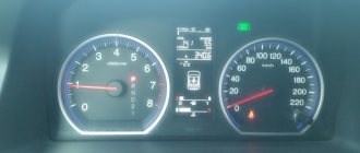
- The instrument panel will go into self-diagnosis mode, all segment positions will light up on the display, all indicators will light up, and the arrows will travel the full path.
- Using the control button on the right steering column switch, we switch between modes (self-diagnosis, firmware version, error codes).
- To reset errors, you need to be in error mode and press and hold the “Reset” button for more than 3s.
- The diagnostic mode exits automatically after inactivity for 20-30 seconds.
Decoding error codes in the dashboard:
- 2-increased voltage of the on-board network;
- 3-fuel level sensor error (if a break in the sensor circuit is detected within 20s);
- 4-error of the coolant temperature sensor (if an open circuit of the sensor is detected within 20s);
- 5-outside temperature sensor error (if there are no sensor readings within 20s, indication on the LCD is “-C”);
- 6-engine overheating (the criterion for triggering the acoustic alarm has been met);
- 7-emergency oil pressure (the criterion for triggering the acoustic alarm is met);
- 8-defect of the brake system (the criterion for triggering the acoustic alarm is met);
- The 9-battery is discharged (the criterion for triggering the acoustic alarm is met);
- E-determination of an error in a data packet stored in EEPROM.
What do these 2 errors mean? And why are there different values in cylinder 1, what is the reason?? And were there any misfires on cylinders 1, 2, 3, 4? Explain your reasons.
Check the coil, look at the connector
0 0 Answer rating: 0
Have you reset the ECU with initialization? Clear the errors and move on. Are there single omissions?
0 0 Answer rating: 0
If there are misfires on all cylinders, something is wrong with the mixture. Possibly poor due to air leaks in the intake (it’s just more common) Errors are nonsense
0 0 Answer rating: 0
Code P1570 is entered if the following conditions are met:
the controller and APS are trained; the controller does not receive a response from the APS control unit. Clear the codes using the Errors menu.
If the code is re-entered, replace the APS control unit
Decoding codes
Well, if you succeed in checking your car for faults, then you need to decipher the combinations of errors, otherwise why do you need diagnostics at all?
Self-diagnosis
Let's look at the decoding of combinations of faults that you can read when checking the Lada Priora yourself.
| Number | Malfunction |
| 2 | When independently checked, this code indicates an increased voltage level in the on-board network. It is recommended to check the main electrical circuits. |
| 3 | Errors have been reported in the operation of the gasoline level control sensor in the fuel tank. |
| 4 | This code indicates a malfunction in the refrigerant temperature level control sensor. |
| 5 | Malfunction of the ambient temperature sensor. The information sent to your device may not be accurate. |
| 6 | The engine is reported to be overheating, and antifreeze may boil. |
| 7 | The BC informs the car owner about the emergency lubricant pressure. |
| 8 | Malfunctions in the brake system were detected. This may indicate defects that may subsequently affect the safety of the driver and passengers. |
| 9 | Low battery reported. |
| E (EEPROM) | Faults have been detected in the data packet. |
The arrows on the dashboard move to maximum values when performing self-diagnosis of the vehicle, and all icons on the panel are lit.
Please note: if the button for switching functions of the on-board computer is not pressed for more than 10 seconds, the dashboard will return to the operating state.
Failures in the ignition system
If you were unable to check your VAZ Priora yourself, you can do this using a special tester. In this case, the error code will be a combination of a letter and four numbers:
- P - means a breakdown in the operation of the electronic systems of the internal combustion engine;
- C - malfunction of the chassis;
- B - breakdown in the electronics of the car interior;
- U - indicates an error in the joint operation of different systems;
- the number 0 indicates the OBD-2 code;
- 1 and 2 - enterprise code;
- 3 - reserve code.
| Combination | Description of the breakdown |
| P0300 | The control unit transmits a signal that there is no spark in all cylinders of the 16-valve car engine. |
| P0326 | Incorrect signal received by the control unit from the knock sensor. It is recommended to perform a more thorough check of the device. |
| P0327 | There is an open or short circuit in the knock sensor circuit. The circuit should be checked. |
| P0335, P0336 | There are errors in the operation of the crankshaft sensor. In addition, such combinations may indicate an incorrect signal coming from the device to the on-board computer. |
| P0337 | The crankshaft position monitoring device shorts to ground. |
| P0338 | There is a short circuit or open circuit in the crankshaft sensor circuit. |
| P0342 | The signal in the headlight sensor circuit is too low |
| P0343 | A too high signal has been detected in the circuit of the same device. |
| P0422 | The neutralizer has broken down; it is recommended to replace the device. |
| P0444 | The Lada Priora control unit detected a break in the wiring of the canister valve. |
| P0445 | The canister valve has shorted to ground. |
| P0480 | There is a break in the wiring of the fan relay; the relay should be checked and, if necessary, replaced. |
| P0481 | There is a short circuit in the cooling fan wiring. |
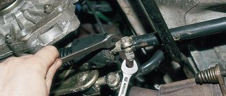
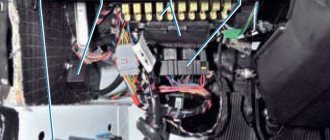
Connector for self-diagnosis of a VAZ Priora car
Fuel and air system error codes
| Codes | Description |
| P0030 | The control unit detected an open circuit from the oxygen sensor heating device to the exhaust gas converter. |
| P0031 | A short to ground is reported in the oxygen sensor circuit. |
| P0102 | An incorrect signal level was detected in the electrical circuit of the mass air flow control device. |
| P0116 | An incorrect signal is received from the coolant temperature monitoring device. You should check the electrical circuit and the condition of the device itself. |
| P0122 | The on-board computer receives an incorrect signal from the TPS. |
| P0130 | The oxygen level control sensor has failed. |
| P0171 | The control unit has detected an excessive amount of air in the fuel mixture. |
| P0172 | The on-board computer detected an excessive amount of gasoline in the fuel mixture. |
| P0201 - P0204 | The Lada Priora control unit detected a break in the wire of one of the four injectors. |
| P0217 | This fault code means the motor is overheating. |
| P0230 | A malfunction has been detected in the electrical circuit of the electric fuel pump relay. It is necessary to carry out a complete diagnosis of the electrical circuit to identify breaks and short circuits. |
| P0261 | There is a short circuit in the wiring of the injector of the first cylinder. |
| P0263 | The driver of the first injector has failed. |
| P0266 | There was a breakdown in the operation of the second injector driver. |
| P0269 | The control unit has registered errors in the functioning of the third injector driver. |
| P0272 | The fourth injector driver has failed. |
| P0264, P0267, P0270 | One of these combinations indicates a short circuit in the second, third or fourth injector circuit. |
Error 1602
If error 1602 appears on the on-board computer of the Lada Priora 16 valves, this means that the on-board voltage in the controller has dropped. As the experience of VAZ 2170 owners shows, error 1602 does not affect the operation of the car; if you remove the terminal from the battery, then 1602 will disappear, but after a while it will appear again. There may be several reasons for 1602:
- Problems with the generator. Measure its voltage; in good condition it produces 13.7-14 V.
- A large voltage drop during engine starting also leads to the appearance of 1602. The ECU records the voltage drop and automatically adjusts the time. First of all, you need to check the ground on the electronic control unit.
- Codes 1602 appear when the security system blocks one of the electrical circuits.
What are the error codes for Lada Priora 8 and 16 valves?
The ECU and on-board computer of cars allow the driver to quickly detect faults. To understand what error information the electronics provide, the car owner must know the decoding of the codes. The most common of them will be discussed below.
Decoding errors
Each error code consists of five characters. The last two characters indicate the serial number of the specific error.
The first character changes based on the fault system in the car:
- P – malfunctions in the operation of the power plant or defects in the operation of the gearbox.
- U – disruption of interaction between system units.
- B – electric lifts, airbag and other defects in body systems.
- C – faults associated with the EUR.
- 3 – reserve;
- 1 and 2 – manufacturer codes;
- 0 – general code for on-board diagnostics.
The third character indicates the nature of the malfunction:
- 1 and 2 – inform about the appearance of defects in the operation of the fuel system or malfunctions during the air supply;
- 3 – breakdown in the ignition system;
- 4 – additional control;
- 5 – incorrectly operating components in idle mode;
- 6 – electronic unit, as well as its circuits;
- 7, 8 – gearbox malfunction.
Error 1602
If the standard on-board computer of the Lada Priora 16 valves showed error 1602, then this indicates that the on-board voltage in the controller has decreased.
As practice has shown, this error 1602 does not affect the performance of Priora in any way.
If you remove the terminal from the battery, the problem disappears for a while, but it will definitely appear again. There may be more than one reason for this error to appear:
- Generator malfunction. To determine accurately, you need to measure its voltage in operating condition, it should be within 14 V.
- A large voltage drop when starting the engine also leads to this error. First of all, you need to check the ground and the ECU.
- This error code also appears when the security system blocks one of the electrical circuits.
Error P1602: what does it mean, decoding
The appearance of error code p1602 when scanning with a diagnostic device or during self-diagnosis using an on-board computer is a fairly common problem. Despite the fact that in the absence of other symptoms of malfunctions, you can use the car without problems, the message itself with error code P1602 begins to irritate. Especially when this has not been happening for the first month. Theoretically, error code 1602 stands for a message from the ECU about an interruption in the on-board network voltage. In practice, this means that in some place there is no contact on the terminals, plugs, connectors.
The message may also mean that one or more electrical devices on the on-board network may not have contact with ground, temporarily or permanently. Naturally, if the battery is not in full contact with the vehicle’s ground, we will not see any message, since the electrical equipment will simply die without signs of life. True, this happens extremely rarely, but it doesn’t hurt to remember it. As well as temporary problems with charging the battery, which can be associated both with the battery itself and with the charging relay, generator or their contacts.
What does error code p1602 mean?
Error p1602 means that the electronic control unit (abbreviated ECU) lost power for some time
At the same time, it is important to distinguish whether it disappeared in emergency mode or was authorized. It is also possible that problems arise in certain areas of the machine’s electrical wiring, causing power loss to the control unit
For example, this could be a relay, battery, generator, broken wires, overload of the electrical system by consumers, and so on.
In most cases, error code p1602 is harmless and does not affect the behavior of the machine. In this case, the Check Engine light on the dashboard does NOT even activate. The “controller voltage interruption” error can occur even when simply removing the negative terminal from the battery to reboot the electronic control unit, but not always (depending on the car, ECU firmware, and so on).
In some cases, it is noted that the car has difficulty starting, especially in cold weather. Therefore, it is advisable to diagnose a breakdown as early as possible, since any minor malfunction can cause significant wear and tear on other engine elements, including expensive ones.
It happens that with such an interruption in the power supply to the electronic control unit from the on-board electrical network, data from the RAM is lost. Then a situation arises when up-to-date information about the lambda probe, knock sensors, misfires, idle speed and others disappears from its memory. Accordingly, after restoring power to the controller, it may generate errors associated with the engine elements listed above. Then the codes should be cleared and when they are entered again, you will need to check the power circuit from the battery to the controller. In VAZ cars this is contact No. 18.
Power surge on board network
Video “Do-it-yourself starter diagnostics”
Find out how to check the unit at home from the video below (author - HF Autoelectrics channel).
All foreign cars currently have various sensors installed that monitor the operation and condition of the car. The modern Lada Priora is no exception to this series. The position and quality of many operating systems in a car depend precisely on how well these sensors perform their duties.
Their main problem is that if some sensors are turned off, the car will not disrupt its operation and can continue to move unhindered. However, the breakdown itself can be detected much later, when the negative consequences of disconnecting the sensors become apparent.
Depending on which sensor fails, fuel consumption may increase sharply, and some malfunctions in the operation of the car’s engine may also occur. In addition, a common “symptom” of sensor disconnection can be accelerated wear and tear of some elements in the car.
In order to check for certain errors on the Priora, you can use a special controller, which is built into the car specifically for this purpose. Thanks to this controller, you don't have to go into the engine compartment with a multimeter to look and identify the problem.
This controller is connected to a special tester, which is connected by manufacturers to the on-board computer. It won’t take much time to perform a full check of the car for any malfunctions in the operation of systems and sensors. You can start the process by pressing two buttons, and then all that remains is to correctly decipher the error codes.
p0504
Also, many owners of a Lada Priora with 16 valves have questions about the appearance of error p0504. She tells the owner that there is a malfunction in the brake pedal sensor. To find out the exact reason for the appearance of p0504, you need to remove the sensor and disassemble it
Pay attention to its springs, one of them could burst - replace the damaged part
Another reason is copper contacts, which can burn. Inspect them and clean them if necessary. Sometimes error p0504 pops up due to the incorrect position of the brake pedal sensor on Priora 16. Twist it and check whether codes p0504 remain on the screen or not.
Self-diagnosis of the Kalina/Priora instrument cluster
- With the ignition off, press the “Reset” button (reset daily mileage). While holding the button, turn on the ignition.
- The instrument panel will go into self-diagnosis mode, all segment positions will light up on the display, all indicators will light up, and the arrows will travel the full path.
- Using the control button on the right steering column switch, we switch between modes (self-diagnosis, firmware version, error codes).
- To reset errors, you need to be in error mode and press and hold the “Reset” button for more than 3s.
- The diagnostic mode exits automatically after inactivity for 20-30 seconds.
Decoding error codes in the dashboard:
- 2-increased voltage of the on-board network;
- 3-fuel level sensor error (if a break in the sensor circuit is detected within 20s);
- 4-error of the coolant temperature sensor (if an open circuit of the sensor is detected within 20s);
- 5-outside temperature sensor error (if there are no sensor readings within 20s, indication on the LCD is “-C”);
- 6-engine overheating (the criterion for triggering the acoustic alarm has been met);
- 7-emergency oil pressure (the criterion for triggering the acoustic alarm is met);
- 8-defect of the brake system (the criterion for triggering the acoustic alarm is met);
- The 9-battery is discharged (the criterion for triggering the acoustic alarm is met);
- E-determination of an error in a data packet stored in EEPROM.
How to reset errors on Kalina? You can reset the errors yourself using the on-board computer, or contact a service station with special diagnostic equipment.
Let us remind you that you can find detailed photo reports in the Lada Kalina repair category.
The electronic control unit and on-board computer in modern car models help the driver quickly find a fault. But to understand electronics, a motorist must be able to decipher codes. In the material you will find a table with all the errors, as well as explanations of the most common codes: 1602, p0504, p0422, p1558. You will also learn how diagnostics are performed.
The process of diagnosing a Lada Priora car using an on-board computer
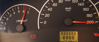
First of all, you need to know how to reset the parameters using the button to reset all daily mileage indicators. It is located on the instrument panel. You must press this button and, while continuing to hold it, you must simultaneously turn on the ignition using the key. Using these steps, you will be able to see all the error codes that have occurred and are available. Before displaying a list of error codes, the vehicle's autonomous self-diagnosis is enabled.
At this time, at the beginning of the diagnostic process, all arrows on sensors and instruments should show a jump from the minimum to the maximum indicator, at the same time at this moment all the necessary indicators and errors for checking the car should be shown on the liquid crystal display.
If at this moment any arrow does not show the correct movement or any position on the display does not appear, then you need to check the sensors and systems of the car for errors. Also, do not forget to check the display itself for faults, because A situation is possible when the car is working correctly, but errors are shown on the display solely due to the separation of any contacts.
Now, in the same mode of self-checking the car, you need to double-click any button that is responsible for switching the operating mode of the on-board computer. After these steps, certain numbers should appear on the on-board computer’s LCD screen. These are the Lada Priora error codes.
| Error code | Decoding |
| 2 | There is quite a strong voltage in the on-board control system. |
| 3 | Malfunction of the sensor, which is responsible for indicating the presence of fuel in the fuel tank. |
| 4 | Problems with the liquid that is responsible for cooling (its temperature readings may be inaccurate). |
| 5 | Failure in the system of sensors responsible for reading the air temperature outside the car |
| 6 | Engine overheating. |
| 7 | The oil pressure level will drop critically. |
| 8 | Problems in the braking system |
| 9 | The battery is dead. |
| E | There were malfunctions in the information package that was stored in the EEPROM |
What does code P0507 mean?
Trouble code P0507 is triggered when the engine idle speed is higher than expected. All modern engines have a desired idle speed - usually between 600-1000 rpm.
The control unit uses position sensing and throttle adjustment to achieve these speeds. If the idle speed exceeds these set values and the maximum adjustment zone, the control unit will generate this error code.
Code P0507 is a common code for vehicles equipped with Electronic Throttle (E-Gas). Newer vehicles usually use E-gas.
The throttle valve is only called electronic. It replaces the old throttle body with a cable between the gas pedal and the throttle body.
The electronic throttle body uses sensors on the gas pedal and an electric motor in the throttle body to provide the desired acceleration. But this does not mean that this error code must necessarily be related to a faulty throttle valve. It can also have many other causes.
IAC check
When checking the sensor, the multimeter must be switched to resistance testing mode. Next, regardless of polarity, you need to connect the probes to terminals A and B, then to C and D. The resistance at the working sensor should be within 53 Ohms.
After this, you need to connect the probe to all terminals one by one. The multimeter should show “infinity” in all connection options.
If the device readings were abnormal, the idle speed sensor can be cleaned or replaced with a new one.
p1558
This error usually occurs on cars with a 127 engine. It is associated with the throttle valve, the quality of which in this power plant leaves much to be desired. P1558 does not interfere with normal engine operation, but you can still try to fix it. Some people solve the problem by flashing it, but we offer a simpler method.
Remove the throttle valve, and then remove the cover - this can be done using a hexagon. We find a plastic gear inside - this is the working part. Lubricate the gear thoroughly and reassemble in reverse order. Most likely, error p1558 will disappear after these manipulations.
System high voltage
Description of the scheme
The ECM monitors the ignition voltage through the ignition circuit to terminal K18 on the ECM. Any signal value above the calibrated value will set a system voltage diagnostic trouble code.
Conditions for Setting the DTC
- The system voltage is less than 16 V.
- Engine running
Action Taken When the DTC Sets
- The malfunction indicator lamp does not light up.
- The controller records the operating conditions at the time the fault is detected. This information is stored in fault logs.
- An archive of diagnostic trouble codes is saved.
Conditions for Clearing DTC/Malfunction Indication
- The DTC history is cleared after 40 consecutive heating cycles without faults.
- The DTC can be cleared by a scan tool.
- The ECM power supply is turned off for more than 10 seconds.
Diagnostic information
If the DTC sets while the accessory drive is operating, check for loose connections or high current. Any circuit that may be causing an intermittent fault should be carefully checked for the following:
- Removed terminals
- Terminal connection
- Lock malfunction
- Deformity
- Terminal damage
- Poor contact between terminals and wiring connectors.
- Physical damage to wiring harnesses
Description of the test
The numbers below indicate the operation numbers in the diagnostic table.
- The On-Board Diagnostic (EOBD) system prompts the technician to perform basic checks and store status and fault data in the scan tool. This creates an electronic copy of the data recorded when a fault occurs. The information is stored in the scanning device for further processing.
- This test is carried out if the generator fails under load.
- The replacement ECM must be programmed. Reprogramming the ECM is described in the latest Techline.
- If no faults have been detected at this stage and no additional fault codes have been set, then see this Diagnostic Information section for additional test information.
DTC P0563 - System Voltage High
| Step | Operation | Values | Yes | No |
| 1 | Perform an On-Board Diagnostic (EOBD) system check. Has the check been completed? | — | Go to Step 2 | Go to “On-Board Diagnostic System Check“. |
| 2 |
Is the voltage below the specified value? | 16 V | Go to Step 3 | Go to Step 5 |
| 3 |
Is the battery voltage less than the specified value? | 16 V | Go to Step 4 | Go to "Diagnostic Information" |
| 4 |
Is the renovation completed? | — | Go to Step 5 | — |
| 5 |
Does the scan tool identify this test as passed and successful? | — | Go to Step 6 | Go to Step 2 |
| 6 | Check to see if additional diagnostic trouble codes have been set. Are diagnostic trouble codes displayed that have not been diagnosed? | — | Go to appropriate DTC table | System OK |
How to check the ignition coil on a Priora with a multimeter
The coil can be checked using a multimeter.
Presence of voltage to the coil
First of all, you need to check the presence of voltage in the connector. Which powers the coil. To do this, you need to remove the connector. Connect the multimeter probe to pin 3 and the second probe to ground. The multimeter should show a voltage of 12 volts.
Winding resistance matching
The next step is to check the resistance of the coil windings between connector No. 2 and the output to the spark plug; the resistance is 300-400 kOhm.
Between pins 1 and 3 approximately 0.5 ohm
If the readings are normal and the coil and cylinder did not work. It is necessary to check the condition of the rubber band. Which is put on a candle. Perhaps it has lost its dielectric properties. Signs of a rubber band failure may include cracks. Loss of elasticity. Gusts of rubber band. All this contributes to the spark breaking through the rubber band onto the body. Not reaching the spark plug electrodes. This rubber band can be replaced. They are on sale.
Checking the coil resistance may not always give the correct result. The test will work if there is a wire break in the coil. Or a short circuit. But the coil may not produce a spark due to interturn breakdown of the wire insulation. If the insulating layer is damaged. A spark jumps between the turns of the coil. In this case, the resistance of the coil in the idle state remains unchanged. Since there is no break or inter-turn short circuit.
And a simple multimeter cannot detect this malfunction. This requires more sophisticated equipment. But in our case everything is obvious. Simply swap the coils and it will become clear that the coil is faulty. If another cylinder stops working.
What does P0562 mean?
12V is the average voltage of an electrical circuit. With the engine running normally, the voltage rises to 13.7 -14.7 Volts. First, the battery provides an electrical impulse to operate the starter and start the generator, then the generator begins to work and power the electrical circuit of the vehicle and charge the battery. Thus, the battery can last 5-7 years. But if the generator works poorly and does not provide the required voltage, the battery quickly becomes depleted and fails. electrical appliances and car devices work worse.
Error 0422
The efficiency of the Priora 16 neutralizer has fallen below the normal level - this is what error p0422 reports to the owner of the Lada Priora 16 valves. As practice shows, codes 0422 pop up quite rarely. If code 0422 appears on the on-board computer screen, then you need to perform the following steps:
- We examine the catalytic collector. Its body and filling must be in good condition;
- If damage is found, the catalytic collector should be replaced with a serviceable one;
- If the catalytic converter is not the cause of the message, then the remaining actions to eliminate p0422 must be entrusted to specialists from the service center.
What does P0443 mean?
Trouble code P0443 means that a malfunction has been detected in the evaporative emission system purge valve circuit.
An evaporative vapor recovery (EVAP) system allows vapors from the gas tank to enter the engine for combustion instead of being released into the atmosphere. The engine control unit (ECU) controls the purge valve by opening it at a specific time, allowing fuel vapor to enter the engine.
The controller also monitors the valve control circuit for fault detection. When the valve is not turned on, the ECU should see high voltage on the ground wire.
When the valve is turned on, the controller should see that the voltage at ground is reduced, close to zero. If the control unit does not see these expected voltages or detects an open circuit, the P0443 code is set.
VAZ errors and their solutions
Owners of domestic cars can easily find a problem with their car. This became possible thanks to the use of on-board computers and the introduction of modern equipment diagnostic tools. This article will describe in detail the errors and how to eliminate them in VAZ 2110, 2112, 2114, Kalina, Priora and how to eliminate them.
How to diagnose a car yourself
Do not rush to go to the service center. Although specialists use test benches to detect malfunctions, and their diagnostics are more accurate, every car owner is still able to find out the cause of the problem using information about the error codes of the on-board computer.
To view error codes recorded by the controller:
- Sit behind the wheel, then press and hold the odometer button. It is located at the bottom of the dashboard.
- Turn the key in the lock to position “1”. While turning the key, release the button. This will be followed by a quick set of readings on the instruments.
- After this, press the button again: the display will show the controller firmware version.
- Finally, press the button the last, third time to display the VAZ controller errors.
VAZ error codes:
- P0030 - Oxygen sensor heater before the converter, control circuit open
- P0031 - Oxygen sensor heater before the converter, control circuit short to ground
- P0032 - Heater of the oxygen sensor to the converter, short circuit of the control circuit to the board. net
- P0036 - Oxygen sensor heater after the converter, control circuit open
- P0037 - Oxygen sensor heater after the converter, control circuit short to ground
- P0038 - Heater of the oxygen sensor after the converter, short circuit of the control circuit to the board. net
- P0102 - Mass air flow sensor circuit, low signal level
- P0103 - Mass air flow sensor circuit, high signal level
- P0112 - Air temperature sensor circuit, low signal level
- P0113 - Air temperature sensor circuit, high signal level
- P0116 - Coolant temperature sensor circuit, signal out of acceptable range
- P0117 - Coolant temperature sensor circuit, low signal level
- P0118 - Coolant temperature sensor circuit, high signal level
- P0122 - Throttle Position Sensor Circuit Low Signal
- P0123 - Throttle Position Sensor Circuit High Signal
- P0130 - The oxygen sensor before the converter is faulty
- P0131 - Oxygen sensor circuit to converter, low output level
- P0132 - Oxygen sensor circuit to converter, high output level
- P0133 - Oxygen sensor circuit to the converter, slow response to changes in mixture composition
- P0134 - The oxygen sensor circuit to the converter is inactive
- P0136 - The oxygen sensor after the converter is faulty
- P0137 - Oxygen sensor circuit after the converter, low signal level
- P0138 - Oxygen sensor circuit after the converter, high signal level
- P0140 - The oxygen sensor circuit after the converter is inactive
- P0141 - Oxygen sensor after the converter, heater is faulty
- P0171 - Fuel supply system too lean
- P0172 - Fuel system too rich
- P0201 - Cylinder 1 injector, control circuit open
- P0202 - Cylinder 2 injector, control circuit open
- P0203 - Cylinder 3 injector, control circuit open
- P0204 - Cylinder 4 injector, control circuit open
- P0217 - Engine temperature is higher than permissible
- P0230 - Fuel pump relay circuit malfunction
- P0261 - Cylinder 1 injector, control circuit short to ground
- P0263 - Injector driver fault 1
- P0264 - Cylinder 2 injector, control circuit short to ground
- P0266 - Faulty injector driver 2
- P0267 - Cylinder 3 injector, control circuit short to ground
- P0269 - Injector 3 driver malfunction
- P0270 - Cylinder 4 injector, control circuit short to ground
- P0262 - Cylinder 1 injector, control circuit shorted to on-board network
- P0265 - Cylinder 2 injector, control circuit shorted to on-board network
- P0268 - Cylinder 3 injector, control circuit shorted to on-board network
- P0271 - Cylinder 4 injector, control circuit shorted to on-board network
- P0272 - Faulty injector driver 4
- P0300 - Random/multiple misfires detected
- P0301 - Cylinder 1, misfire detected
- P0302 - Cylinder 2, misfire detected
- P0303 - Cylinder 3, misfire detected
- P0304 - Cylinder 4, misfire detected
- P0326 - Knock sensor circuit, signal output out of acceptable range
- P0327 - Knock sensor circuit low signal
- P0328 - Knock sensor circuit, high signal level
- P0335 - Crankshaft position sensor circuit is faulty
- P0336 - Crankshaft position sensor circuit, signal out of acceptable range
- P0337 - Crankshaft position sensor, short to ground
- P0338 - Crankshaft position sensor, open circuit
- — Malfunction of the camshaft position sensor
- P0342 - Phase sensor circuit, low signal level
- P0343 - Phase sensor circuit, high signal level
- P0346 - Phase sensor circuit, signal output out of acceptable range
- P0351 - Ignition coil of cylinder 1 (1-4), control circuit open
- P0352 - Ignition coil of cylinder 2 (2-3), control circuit open
- P0353 - Ignition coil of cylinder 3, control circuit open
- P0354 - Ignition coil of cylinder 4, control circuit open
- P0363 - Misfire detected, fuel supply to idle cylinders is turned off
- P0422 - Neutralizer efficiency below threshold
- P0441 - Gasoline vapor recovery system, incorrect air flow through the canister purge valve
- P0444 - Canister purge valve, control circuit open
- P0445 - canister purge valve, control circuit short to ground or on-board network
- P0480 - Fan relay, control circuit open
- P0481 - Cooling fan 2 circuit malfunction
- P0500 - Vehicle speed sensor is faulty
- P0506 - Idle system, low engine speed
- P0507 - Idle system, high engine speed
- P0511 - Idle speed control, control circuit faulty
- P0560 - On-board network voltage is below the system operability threshold
- P0562 - On-board voltage, low level
- P0563 - On-board voltage, high level
- P0601 - Engine control system controller, ROM checksum error
- P0615 - Additional starter relay, control circuit open
- P0616 - Additional starter relay, control circuit short to ground
- P0617 - Additional starter relay, control circuit shorted to on-board network
- P0627 - Fuel pump relay, control circuit open
- P0628 - Fuel pump relay, control circuit short to ground
- P0629 - Fuel pump relay, control circuit shorted to on-board network
- P0645 - Air conditioning compressor clutch relay, control circuit open
- P0646 - Air conditioning compressor clutch relay, control circuit short to ground
- P0647 - Air conditioning compressor clutch relay, control circuit shorted to board. net
- P0650 - Malfunction indicator lamp, control circuit faulty
- P0654 - Instrument cluster tachometer, control circuit faulty
- P0685 - Main relay, control circuit open
- P0686 - Main relay, control circuit short to ground
- P0687 - Main relay, control circuit shorted to on-board network
- P0691 - Fan relay, control circuit short to ground
- P0692 - Fan relay, control circuit shorted to on-board network
- P1102 - Oxygen Sensor Heater Resistance Low
- P1115 - Faulty oxygen sensor heating circuit
- P1123 - Rich mixture at idle
- P1124 - Lean mixture at idle
- P1127 - Rich mixture at Partial Load
- P1128 - Lean mixture in Partial Load mode
- P1135 - Oxygen sensor heater circuit 1 open, short circuit
- P1136 - Rich mixture in Light Load mode
- P1137 - Lean mixture in Light Load mode
- P1140 - Measured load differs from calculation
- P1141 - Post-converter oxygen sensor 1 heater malfunction
- P1171 - Low level CO potentiometer
- P1172 - High level CO potentiometer
- P1301 - Cylinder 1, misfire detected, critical for the converter
- P1302 - Cylinder 2, misfire detected, critical for the converter
- P1303 - Cylinder 3, misfire detected, critical for the converter
- P1304 - Cylinder 4, misfire detected, critical for the converter
- P1386 - Knock Channel Test Error
- P1410 - Canister purge valve control circuit short circuit to +12V
- P1425 - Canister purge valve control circuit short circuit to ground
- P1426 - Canister purge valve control circuit open
- P1500 - Fuel pump relay control circuit open
- P1501 - Short circuit to ground of the fuel pump relay control circuit
- P1502 - Short circuit to +12V fuel pump relay control circuit
- P1509 - Idle Air Control Circuit Overload
- P1513 - Idle air control circuit short circuit to ground
- P1514 - Idle air control circuit short circuit to +12V, open
- P1541 - Fuel pump relay control circuit open
- P1570 - Immobilizer, circuit faulty
- P1602 - Engine control system controller, power supply loss
- P1606 - Rough road sensor circuit, signal out of acceptable range
- P1616 - Rough Road Sensor Circuit Low Signal
- P1617 - Rough road sensor circuit, high signal level
- P2301 - Ignition coil of cylinder 1 (1-4), control circuit shorted to board. net
- P2303 - Ignition coil of cylinder 2 (2-3), control circuit shorted to board. net
- P2305 - Ignition coil of cylinder 3, control circuit shorted to board. net
- P2307 - Ignition coil of cylinder 4, control circuit shorted to board. net
We recommend: Is it possible to eliminate the hum in the power steering on your own?
Mass air flow sensor
- P0101 - Diagnosis of reality. Air flow is out of range
- P0102 - Low value diagnostics. The signal period is greater than the upper maximum permissible value
- P0103 - High value diagnostics. The signal period is less than the lower maximum permissible value
Intake air temperature sensor
- P0112 - Low value diagnostic. Voltage is less than the lower maximum permissible value
- P0113 - Diagnostics high value. Voltage is greater than the upper maximum permissible value
Coolant temperature sensor
- P0116 - Diagnosis of reality. Temperature is less than calculated value
- P0117 - Low value diagnostic. Voltage is less than the lower maximum permissible value
- P0118 - Diagnostics high value. Voltage is greater than the upper maximum permissible value
Throttle Position Sensors
- P2135 - Diagnostics of the mismatch between the signals of two sensors. The sensor voltages differ by the threshold value
- P0122 - Low value diagnostic (sensor 1). Voltage is less than the lower maximum permissible value
- P0123 - High value diagnostic (sensor 1). Voltage is greater than the upper maximum permissible value
- P0222 - Low value diagnostic (sensor 2). Voltage is less than the lower maximum permissible value
- P0223 - High value diagnostic (sensor 2). Voltage is greater than the upper maximum permissible value
Accelerator pedal position sensors
- P2138 - Diagnostics of the mismatch between the signals of two sensors. The sensor voltages differ by the threshold value
- P2122 - Low value diagnostic (sensor 1). Voltage is less than the lower maximum permissible value
- P2123 - High value diagnostic (sensor 1). Voltage is greater than the upper maximum permissible value
- P2127 - Low value diagnostic (sensor 2). Voltage is less than the lower maximum permissible value
- P2128 - High value diagnostic (sensor 2). Voltage is greater than the upper maximum permissible value
Injectors
- P0201, P0202, P0203, P0204 - Diagnostics of open control circuit. Driver diagnostics
- P0261, P0264, P0267, P0270 - Diagnosis of control circuit short circuit to ground.
- P0262, P0265, P0268, P0271 - Diagnostics of a short circuit in the control circuit to the on-board network.
We recommend: Difficulties that arise when buying a used car
Control oxygen sensor
- P0130 - Signal circuit integrity diagnostics. Voltage is less than the lower maximum permissible value or greater than the upper maximum permissible value
- P0131 - Low value diagnostic. Voltage is less than the lower maximum permissible value
- P0132 - Diagnostics high value. Voltage is greater than the upper maximum permissible value
- P0133 - Slow Response Diagnosis. The signal period is greater than the maximum permissible value
- P0134 - Activity Diagnostics. Voltage is less than the upper maximum permissible value and greater than the lower maximum permissible value
- P0030 - Diagnostics of open circuit of the heater. Driver diagnostics
- P0031 - Diagnostics of a short circuit of the heater circuit to ground.
- P0032 - Diagnostics of a short circuit of the heater circuit to the on-board network.
Diagnostic oxygen sensor
- P0136 - Signal circuit integrity diagnostics. Voltage is less than the lower maximum permissible value or greater than the upper maximum permissible value
- P0137 - Low value diagnostic. Voltage is less than the lower maximum permissible value
- P0138 - Diagnostics high value. voltage is greater than the upper maximum permissible value
- P0140 - Activity Diagnostics. Voltage is less than the upper maximum permissible value and greater than the lower maximum permissible value
- P0036 - Heater circuit open circuit diagnostics. Driver diagnostics
- P0037 - Diagnostics of a short circuit of the heater circuit to ground.
- P0038 - Diagnostics of a short circuit of the heater circuit to the on-board network.
Fuel supply system
- P0171 - Diagnosis of poor mixture composition. Fuel correction coefficients are greater than the upper maximum permissible value
- P2187 - Diagnosis of poor mixture composition (at idle).
- P0172 - Diagnostics of the richness of the mixture. Fuel correction coefficients are less than the lower maximum permissible value
- P2188 - Diagnostics of the richness of the mixture (at idle).
- Engine overheating - P0217. Engine temperature monitoring
Misfire for toxicity
- P0300, P0301, P0302, P0303, P0304 - Diagnosis of the presence of misfires affecting toxicity. The number of misfires is greater than the maximum permissible value
Misfire to protect the converter
- P0363, P1301, P1302, P1303, P1304 - Diagnosis of the presence of misfires affecting the converter. The number of misfires is greater than the maximum permissible value
Knock sensor
- P0326 - Low value diagnostics. Normalized signal level is outside the acceptable range
- P0327 - Low value diagnostics. The normalized signal level is less than the lower maximum permissible value
- P0328 - High value diagnostics. The normalized signal level is greater than the upper maximum permissible value
Crankshaft position sensor
- P0335 - Signal presence diagnostics. Change in air flow in the absence of a signal from the crankshaft position sensor above the maximum permissible value
- P0336 - Diagnosis of reality. The controller counts the wrong number of teeth per revolution of the crankshaft
Camshaft position sensor
- P0340 - Diagnostics of signal presence. The sensor signal does not change when the engine is running
- P0342 - Low value diagnostics. Low sensor signal for several crankshaft revolutions
- P0343 - High value diagnostics. High sensor signal for several crankshaft revolutions
Ignition coils
- P0351, P0352 - Open circuit diagnostics. The primary circuit current is less than the maximum permissible value
- P2301, P2304 - Diagnostics of a short circuit to the on-board network. The primary circuit current is greater than the maximum permissible value
- Neutralizer - P0422. Determining the capacity of stored oxygen by comparing the amplitude range of the control and diagnostic oxygen sensors
Canister purge valve
- P0441 - Functional diagnostics. The response of the idle control system is greater or less than the maximum permissible value
- P0459 - Diagnostics of a short circuit to the on-board network. Driver diagnostics
- P0458 - Diagnostics of a short circuit to ground.
- P0444 - Open circuit diagnostics.
Cooling fan relay 1
- P0692 - Diagnostics of a short circuit to the on-board network. Driver diagnostics
- P0691 - Diagnostics of a short circuit to ground.
- P0480 - Open circuit diagnostics.
Cooling fan relay 2
- P0694 - Diagnostics of a short circuit to the on-board network. Driver diagnostics
- P0693 - Diagnostics of a short circuit to ground.
- P0481 - Open circuit diagnostics.
- Cooling fan - P0485. Diagnostics of cooling fan supply voltage
- Vehicle speed sensor - P0500. Signal presence diagnostics
- Brake pedal sensor - P0504. Diagnostics of sensor signal mismatch time
Onboard voltage
- P0560 - Diagnosis of value validity. voltage in circuits Cl. "30" and Cl. “15” differs by the threshold value
- P0562 - Low value diagnostic. Voltage is less than the lower maximum permissible value
- P0563 - High value diagnostic. Voltage is greater than the upper maximum permissible value
- P1602 - Supply voltage diagnostics. Power failure
Controller
- P1640 - EEPROM diagnostics. EEPROM test error
- P0601 - Software checksum diagnostics. Invalid checksum
- P0606 - Internal controller checks. ADC is faulty
- P2105 - The monitoring module is faulty.
Starter relay
- P0615 - Open circuit diagnostics. Driver diagnostics
- P0616 - Diagnosis of a short circuit to ground.
- P0617 - Diagnostics of a short circuit to the on-board network.
Fuel pump relay
- P0627 - Open circuit diagnostics. Driver diagnostics
- P0628 - Diagnosis of a short circuit to ground.
- P0629 - Diagnostics of a short circuit to the on-board network.
A/C clutch relay
- P0645 - Open circuit diagnostics. Driver diagnostics
- P0646 - Diagnostics of a short circuit to ground.
- P0647 - Diagnostics of a short circuit to the on-board network.
How to remove information about corrected errors from the controller memory
Sometimes, after troubleshooting, error messages remain in memory and periodically appear on the panel.
To clear an error code from memory:
- Write down and check for irrelevant codes that appear.
- Reset the daily mileage readings by pressing the corresponding button, after which the error code is guaranteed to be deleted from memory.
How to get rid of the "Check Engine" message
Sometimes drivers see a glowing orange icon at the bottom of the instrument panel. This is how the computer reports an engine malfunction. Self-diagnosis will not allow you to determine and correct the cause of the motor problem. However, the error often appears on serviceable cars. Therefore, to reset the problem code:
- Turn on the ignition, but do not start the car.
- Open the hood and use a wrench to loosen and remove the negative terminal on the battery.
- After a minute, return the terminal to its original position.
- Close the hood and turn the ignition key to position “0”.
- Turn the ignition back on and start the engine. After a short time the error should disappear.
We recommend: Cooling radiator - features, tasks and types
If the above instructions did not help, it is worth carrying out a more accurate diagnosis of the car at a service center in order to correct the problem at an early stage.
Error 1602
If error 1602 appears on the on-board computer of the Lada Priora 16 valves, this means that the on-board voltage in the controller has dropped. As the experience of VAZ 2170 owners shows, error 1602 does not affect the operation of the car; if you remove the terminal from the battery, then 1602 will disappear, but after a while it will appear again. There may be several reasons for 1602:
- Problems with the generator. Measure its voltage; in good condition it produces 13.7-14 V.
- A large voltage drop during engine starting also leads to the appearance of 1602. The ECU records the voltage drop and automatically adjusts the time. First of all, you need to check the ground on the electronic control unit.
- Codes 1602 appear when the security system blocks one of the electrical circuits.
Error 0422
The efficiency of the Priora 16 neutralizer has fallen below the normal level - this is what error p0422 reports to the owner of the Lada Priora 16 valves. As practice shows, codes 0422 pop up quite rarely. If code 0422 appears on the on-board computer screen, then you need to perform the following steps:
- We examine the catalytic collector. Its body and filling must be in good condition;
- If damage is found, the catalytic collector should be replaced with a serviceable one;
- If the catalytic converter is not the cause of the message, then the remaining actions to eliminate p0422 must be entrusted to specialists from the service center.
Self-diagnosis
Once the main code errors have been studied, you can perform self-diagnosis of the car. The Lada Priora has a special controller that allows you to perform diagnostics. If an on-board computer is installed in the car interior, then diagnostics are performed with its help. In addition, there is special equipment that allows you to more accurately perform this procedure.
Diagnostics begins with activation of the test mode. The procedure is performed as follows:
- Turn off the ignition and hold down the mileage reset button, then turn it on again without releasing the button.
- When the ignition is turned on, all components located on the instrument panel will begin to glow. All devices will begin to move to the maximum mark, and then back. This behavior of the car indicates the beginning of the diagnosis.
- Next, we move on to the right steering wheel switch, on which there is a button for switching the settings of the on-board computer. After clicking on it, an information message with the software version will appear on the screen.
- After pressing the button again, error diagnostics will begin. Error codes will appear on the display, which can be deciphered using the corresponding table.
- Once the diagnostics are complete, you can reset the error data. To do this, hold down the mileage reset button for five seconds.
p1558
This error usually occurs on cars with a 127 engine. It is associated with the throttle valve, the quality of which in this power plant leaves much to be desired. P1558 does not interfere with normal engine operation, but you can still try to fix it. Some people solve the problem by flashing it, but we offer a simpler method.
Remove the throttle valve, and then remove the cover - this can be done using a hexagon. We find a plastic gear inside - this is the working part. Lubricate the gear thoroughly and reassemble in reverse order. Most likely, error p1558 will disappear after these manipulations.
How is self-diagnosis performed?
We have sorted out the main errors on the Priora, now it’s worth finding out how self-diagnosis is performed. The VAZ 2170 with 16 valves has a special controller with which diagnostics are performed. If you have an on-board computer installed, then diagnostics are performed on it. There is also special equipment that allows for a more in-depth check of Priora 16 class systems.
Since most Priora 16 cars already have an on-board computer, we will consider the option without the use of special devices. Diagnostics begins with activation of the test mode. The work proceeds according to the following scheme:
- Turn off the ignition. Now we hold down the daily mileage reset button, without releasing the button, we start the ignition of the Priora 16 cl;
- On the instrument panel you will see a display with an indication. After turning on the ignition, all components of the instrument panel will light up. The needles of the temperature, speedometer, tachometer and other instruments will begin to move to the maximum level and back. This behavior indicates that self-diagnosis has begun;
- Let's move on to the right steering wheel switch. Here you will find a button for switching the on-board computer settings. Click on it, a message with the software version will appear on the instrument panel screen;
- The instrument panel error diagnosis will begin if you press this key again. Various codes will appear on the display, which you can decipher in the table below;
- When the diagnostics are complete, you can reset the error data. Press and hold the daily mileage reset button for about 5 seconds.
Hello. I got error 1570 on BC - “immobilizer, no positive response or open circuit.” It appears when you turn the ignition key in the form of a beeping buzzer (the car with the key on the dashboard does not blink or light up), and it does not stop for some time after starting the engine. Resetting the error does not help. How to defeat her?
What is included in the Priora instrument cluster
This unit serves to inform the driver about the condition of his car. Devices that project information are divided into three categories:
- Displays.
- Pointers.
- Indicators (control lamps).
Each of them performs strictly defined functions. They are worth considering separately.
Displays
Liquid crystal screens (LCD) are small in size. In general, they serve as a monitor for the instrument panel ECU. They display the total and daily mileage of the car, as well as some on-board computer data. Switching between information output modes and control is carried out using buttons located on the steering column wiper switch, to the right of the steering wheel. The rules for using this functionality are described in detail in the “Priora Operating Instructions” included with each machine. Therefore, it makes no sense to present them here.
Signposts
These are pointer instruments that have a scale on which the arrow marks the exact value of the observed parameter. The Priora instrument clusters have the following indicators:
- Speedometer (indicates vehicle speed).
- Tachometer (engine speed).
- Temperature indicator (degree of motor heating).
- Fuel indicator (amount of gasoline in the tank).
All these devices operate based on data received from various sensors. They are processed by the internal ECU of the instrument panel and produces the result.
Indicators
This is the most numerous type of dashboard informant. The number of installed indicator lights depends on the type of instrument panel and the Priora equipment class, since almost all additional devices have their own indicator lamps on the dashboard. Although there is a set of indicators required for any car:
- Battery charge indicator lamp.
- Indicator of emergency oil pressure in the system.
- "Check Anger" lamp for ECU control.
- Turn signals, 2 pcs.
- Minimum fuel level.
- Critical brake fluid level.
- Turning on the side lights.
- High beam headlights.
- Anti-theft system warning light.
Error code P1602 indicates that the controller power supply voltage is lost.
Error P1602 stands for “Control system controller, loss of on-board power supply voltage.” In the understanding of this error, the controller means the electronic engine control unit (ECU), since the error begins with the letter “P”.
p, blockquote 1,0,0,0,0 —>
p, blockquote 2,0,0,0,0 —>
This error belongs to the class of system errors, since it does not specifically indicate a faulty device or unit. Therefore, eliminating error P1602 is carried out by monitoring possible locations of the malfunction.
p, blockquote 3,0,0,0,0 —>
p, blockquote 4,0,0,0,0 —>
Decoding errors
Each code consists of five characters: P 1 4. Let's say right away about the fourth and fifth characters - they indicate the serial number of the error. Now it’s worth taking a closer look at what the codes consist of
The first character may vary depending on the vehicle system:
- P – malfunctions in the operation of the power plant; the symbol also indicates defects in the automatic transmission.
- U – you need to look for a fault in the interaction node between the system units.
- B – defects in the operation of body systems, which include electric lifts, airbags, etc.
- C – chassis sensors have detected a malfunction in the chassis system.
Let's move on to the second character:
- 3 – reserve.
- 2 and 1 – codes set by the manufacturer.
- – common code for on-board diagnostics (OBD-II).
The third symbol indicates to the motorist the type of breakdown:
- 1 and 2 - indicate defects in the operation of the fuel unit or the appearance of malfunctions during the air supply.
- 3 – breakdowns in the ignition unit.
- 4 – indicates auxiliary control.
- 5 – in idle mode, some components do not work correctly.
- 6 – electronic unit or its circuits.
- 7 and 8 – defects in the operation of the gearbox.
The process of diagnosing a car using a tester or a connected computer
Much more accurate and reliable data when checking a car for malfunctions can be obtained if you use separately connected equipment. But the introduction of such tools and devices gives encrypted readings, therefore, in order to correctly understand and find all the faults in the car, you need to decrypt the data received from diagnostic devices.
Of course, manufacturers could have done things easier for Russian-speaking car enthusiasts. It would be possible to write “replace the canister valve” on the device screen after diagnostics, but instead, only a code in the form of p0441 can be found on the display, and code p0130 will appear only due to problems with the oxygen sensor.
But the problem is that Lada Priora is produced not only for the domestic market, it is also produced for sale in other countries. Therefore, such a classification of automobile problems and their code on the testing device was created.
It is easier to enter only a certain number of universal codes into the program than to enter your own language data for each national market . As a result, you can look at a specific code on the display and easily determine the essence of the problem in the car using a list that lists all encrypted codes. A special code is used to indicate error codes on the Lada Priora car. This cipher includes:
- letter fault code;
- digital code for the location of a malfunction in the vehicle design.
On the Lada Priora, all gap codes in the vehicle's operation will have five digits. Here is a complete list of Priora designations. The first character of the code will be a Latin letter. The letter “P” indicates problems with the engine, or more precisely with its electronic system. The letter “B” indicates problems with the interior electronics.
The letter “C” is present on the screen only if there are failures in the electronic system of the vehicle chassis. If combined errors occur in several operating systems of the vehicle, the letter “U” will appear on the display. The letter designation is followed by a number.
The zero indicator is indicated by the OBD-2 code. Numbers 1 and 2 show the company code, and the third digit is responsible for the backup code. The subsequent set of numbers conditionally shows the place where errors were detected during diagnostics. A zero code indicates the exhaust system. Number 1 indicates the fuel system, number 2 indicates the air supply system.
If there is a malfunction in the ignition, then the number 3 will appear. If there are problems with additional control, the number 4 will appear. If there are malfunctions in the idle speed, then the number 5 is responsible for this, and if there are problems in the ECU, the number 6 will appear. Numbers 7 and 8 are associated with the transmission In the general code, the very last two digits indicate the error number in the operation.
p0504
Also, many owners of a Lada Priora with 16 valves have questions about the appearance of error p0504. She tells the owner that there is a malfunction in the brake pedal sensor. To find out the exact reason for the appearance of p0504, you need to remove the sensor and disassemble it
Pay attention to its springs, one of them could burst - replace the damaged part
Another reason is copper contacts, which can burn. Inspect them and clean them if necessary. Sometimes error p0504 pops up due to the incorrect position of the brake pedal sensor on Priora 16. Twist it and check whether codes p0504 remain on the screen or not.
HOW CAN YOU CHECK COILS
In any case, checking the ignition coil on a Priora always begins with its external inspection. Even very small cracks or tears in its elastic bands are not allowed. Their presence indicates that the device has been replaced. Cracks, chips and other damage to plastic parts indicate that the coil was overheated and it could simply “burn out”. Next, the internal parts are inspected, especially the spiral, its location. If the inspection does not reveal any visible defects, proceed to further inspection.
There are several ways to check the ignition coil, which will be discussed below. During the operation of the machine, it is not often, but there is a need to check it. Doing this when there are no obvious signs of failure is not easy without special equipment such as a spark gap or an oscilloscope. Let's look at how to check the ignition coil without instruments. To begin with, you can simply swap the devices and see how the engine behaves after that. If the interruptions move into the cylinder along with the coil, then there is a malfunction in it and it needs to be replaced.
You can check the high-voltage ignition coil directly on the car. To do this, you need to remove it from the engine, insert a working spark plug into the high-voltage terminal, turn off the fuel pump and, with the ignition on, crank the engine with the starter. A working coil will show itself as a spark on the spark plug . In this case, you must beware of high voltage and use protective equipment.
In cars that have an on-board computer installed, the system will report problems in the cylinders with a signal in the form of numbers from 0301 to 0304, where the last digit indicates the number of the “problem” cylinder. All that remains is to figure out who is to blame, the coil or the spark plug.
INSTRUMENTAL COIL CHECK
After visual inspection and control, you can begin checking using measuring instruments. It is best to use digital multimeters for these purposes, or devices such as MD-1 or AZ-1. They can be freely purchased, and their price is low. Now let's talk about how to check the ignition coil on a Priora using instruments.
Before checking, the device must be removed from the engine. This can be done this way:
- Disconnect the battery terminals;
- Remove the protective plastic casing from the engine;
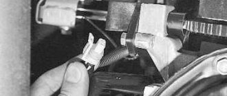
- Squeeze the latch with your fingers and disconnect the connector with wires;
- Using a “10” wrench, unscrew the fastening bolt and remove the coil from the mounting socket.
We unscrew the coil with a key - it’s simple!
(naturally, the internal combustion engine has 16 valves, a coil of spark plugs in the well) Now you can start checking with instruments. First you need to check and calibrate the measuring device. To do this, set the measurement switch to the position for measuring resistance at “200 Ohms”, and connect the probes to each other. The readings should be close to “0”. These readings must be remembered or written down. They may be useful in the future. The device is calibrated, you can begin testing. Testing with a multimeter is carried out in the following order:
- Both probes of the device are connected to the coil connector (polarity is not necessary) and the resistance of the primary (low-voltage) winding is measured. Pinout of contacts for measurements 1 and 3, measuring limit of the device is “200 Ohm”. It should show approximately 0.8 ohms. The indicator obtained during calibration is subtracted from this value and the true value of the winding resistance is obtained. If there are no readings, you need to check the reliability of the contact between the probes and the coil leads. If after several attempts the readings do not appear, it means that there is a break in the primary winding and it must be replaced;
- The next step will be to check the high voltage winding. Set the resistance measurement limit to 2 MΩ. In this case, polarity must be observed, since the high-voltage winding has a diode. Therefore, the red probe is inserted into the coil terminal, and the black one is connected to the connector terminal number 2, which is the middle one in the block. The device should show approximately 342 kOhm. It should be taken into account that the readings of the device are highly dependent on the heating of the coil. It is best to test on a cold coil. In this case, it is also necessary to ensure good contact of the device probe with the high-voltage terminal. If the readings are close to infinity, the part needs to be replaced.
Checking with a multimeter
A little about whether it is possible to repair the ignition coil. It is not possible to restore the primary or secondary winding, but even novice drivers can replace the tip on it. To do this, stock up:
- New tip:
- New sealing ring;
- Degreasing agent;
- High temperature silicone sealant.
The site where the tip is installed is cleaned and thoroughly degreased. The skirt of the new tip must be turned inside out and a small layer of sealant applied to it. While it dries a little, install a new O-ring. Next you need to install the rubber tip in its place. This will complete the repairs.