Sometimes you need to look at something and, so as not to search, add it to your blog. Click on the picture to enlarge the diagram. All signatures are below the diagram.
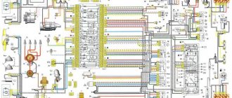
1 — block headlights; 2 — side direction indicators; 3 - battery; 4 — starter activation relay; 5 — carburetor electro-pneumatic valve; 6 — carburetor microswitch; 7 - generator 37.3701; 8 — gearmotors for headlight cleaners*; 9 — electric motor of the engine cooling system fan*; 10 — fan motor activation sensor*; 11 — sound signals; 12 — ignition distributor; 13 — spark plugs; 14 — starter; 15 — coolant temperature indicator sensor; 16 — engine compartment lamp; 17 — oil pressure warning lamp sensor; 18 — ignition coil; 19 — brake fluid level sensor; 20 — windshield wiper gearmotor; 21 — carburetor electro-pneumatic valve control unit; 22 — electric motor of the headlight washer pump*; 23 — electric motor of the windshield washer pump; 24 — brake light switch; 25 — windshield wiper relay; 26 — instrument lighting regulator; 27 — relay-breaker for alarm and direction indicators; 28 — reverse light switch; 29 — plug socket for a portable lamp**; 30 — cigarette lighter; 31 — glove box lighting lamp; 32 — mounting block (a jumper is installed instead of a short-circuit relay); 33 — lamp switches on the front door pillars; 34 — lamp switches on the rear door pillars; 35 — lampshades; 36 — parking brake warning lamp switch; 37 — switch for the carburetor air damper warning lamp; 38 — alarm switch; 39 — three-lever switch; 40 — ignition switch; 41 — ignition relay; 42 — external lighting switch; 43 — rear fog light switch; 44 — fog light circuit fuse; 45 — oil pressure warning lamp; 46 — instrument cluster; 47 — fuel reserve warning lamp; 48 — fuel level indicator; 49 — battery charge indicator lamp; 50 — coolant temperature indicator; 51 — control lamp for the carburetor air damper; 52 — parking brake warning lamp; 53 — control lamp block; 54 — rear fog light indicator lamp; 55 — control lamp for heated rear window; 56 — brake fluid level warning lamp; 57 - voltmeter; 58 — speedometer; 59 — control lamp for external lighting; 60 — turn signal indicator lamp; 61 — control lamp for high beam headlights; 62 — heater fan switch; 63 — rear window heating switch with backlight*; 64 — block for connecting the bar; 65 — heater fan electric motor; 66 — additional resistor of the heater electric motor; 67 — rear lights; 68 — pads for connecting to the rear window heating element; 69 — sensor for level indicator and fuel reserve; 70 — license plate lights.
The order of conditional numbering of plugs in the blocks: a - headlight units and headlight cleaners, windshield wiper relay breaker, carburetor electric pneumatic valve control unit; b - mounting block and three-lever switch; c — rear lights (numbering of pins from the edge of the board); d — relay-interrupter of the alarm and direction indicators.
Schematic electrical diagrams, connecting devices and pinouts of connectors
The VAZ 2104 with rear-wheel drive and a station wagon body was produced from 1983 to 2012. The model was constantly improved: electrical equipment was changed, a fuel injection system, a five-speed gearbox and semi-sports front seats appeared. The VAZ 21043 modification was supplemented with a system for cleaning and heating the rear door window. Information on the diagrams is intended for self-repair of cars. Electrical circuits are divided into several blocks for ease of viewing via a computer or phone; there are also files in the form of a single picture with a description of each element - for printing on a printer.
VAZ-2104 diagram (old version)
- block headlights;
- — side direction indicators;
- - accumulator battery;
- — starter activation relay;
- — carburetor electro-pneumatic valve;
- — carburetor microswitch;
- — generator 37.3701;
- — gearmotors for headlight cleaners;
- — electric motor of the engine cooling system fan*;
- — fan motor activation sensor*;
- — sound signals;
- — ignition distributor;
- - spark plug;
- — starter;
- — coolant temperature indicator sensor;
- — engine compartment lamp;
- — oil pressure warning lamp sensor;
- - ignition coil;
- — brake fluid level sensor;
- — gear motor for windshield wiper;
- — carburetor electro-pneumatic valve control unit;
- — electric motor of the headlight washer pump;
- — electric motor of the windshield washer pump;
- — brake light switch;
- — windshield wiper relay;
- — instrument lighting regulator;
- — relay-breaker for alarm and direction indicators;
- — reverse light switch;
- — plug socket for a portable lamp*;
- - cigarette lighter;
- — glove box lighting lamp;
- — mounting block;
- — lamp switches on the front door pillars;
- — lamp switches on the rear door pillars;
- - lampshades;
- — parking brake warning lamp switch;
- — switch for the carburetor air damper warning lamp;
- — tailgate glass cleaner and washer switch;
- - hazard warning switch;
- — three-lever switch;
- — ignition switch;
- - ignition relay;
- — external lighting switch;
- — rear fog light switch;
- — fog light circuit fuse;
- — oil pressure warning lamp;
- — instrument cluster;
- — fuel reserve warning lamp;
- — fuel level indicator;
- — courtesy light for the rear part of the cabin;
- — battery charge indicator lamp;
- — coolant temperature gauge;
- - carburetor air damper warning lamp;
- — parking brake warning lamp**;
- — block of warning lamps;
- — rear fog light indicator lamp;
- — control lamp for heated rear door glass;
- — brake fluid level warning lamp;
- - voltmeter;
- — speedometer 2104;
- — control lamp for external lighting;
- — turn signal indicator lamp;
- — high beam warning lamp;
- — heater fan switch;
- — heated tailgate glass switch with backlight;
- — heater fan electric motor;
- — additional resistor for the heater electric motor;
- — electric motor of the tailgate glass washer pump;
- — rear lights;
- — gearmotor for tailgate glass wiper;
- — pads for connecting to the rear glass heating element;
- — license plate lights;
- — sensor for level indicator and fuel reserve.
A
— headlight units, headlight and tailgate glass cleaners, windshield wiper relay-breaker, carburetor electro-pneumatic valve control unit;
b
- mounting block and three-lever switch;
c
— rear lights (pin numbering in order from top to bottom);
d
— relay-interrupter of the alarm and direction indicators.
Electrical diagram of VAZ 2104
Scheme of VAZ-2104, for cars of early years of production. It is distinguished from the standard circuit by the G-222 generator, 10-pin hazard warning switch, 5-pin relay for direction indicators and hazard warning lights, top dead center sensor of the 1st cylinder, diagnostic block, rear window heating indicator lamp directly in the switch , the absence of a carburetor choke warning lamp, a two-position exterior lighting switch and a three-position steering column light switch.
1 — block headlights; 2 — side direction indicators; 3 - battery; 4 — battery charge warning lamp relay; 5 — carburetor electro-pneumatic valve; 6 — top dead center sensor of the 1st cylinder; 7 — carburetor microswitch; 8 — generator G-222; 9 — gearmotors for headlight cleaners*; 10 — electric motor of the engine cooling system fan*; 11 — fan motor activation sensor*; 12 — sound signals; 13 — ignition distributor; 14 — spark plugs; 15 - starter; 16 — coolant temperature indicator sensor; 17 — engine compartment lamp; 18 — oil pressure warning lamp sensor; 19 — ignition coil; 20 — brake fluid level sensor; 21 — windshield wiper gearmotor; 22 — carburetor electro-pneumatic valve control unit; 23 — electric motor of the headlight washer pump*; 24 — electric motor of the windshield washer pump; 25 — diagnostic block; 26 — brake light switch; 27 — windshield wiper relay; 28 — relay-interrupter for alarm and direction indicators; 29 — reverse light switch; 30 — plug socket for a portable lamp; 31 — cigarette lighter; 32 — glove box lighting lamp; 33 — mounting block (a jumper is installed instead of a short-circuit relay); 34 — lamp switches on the front door pillars; 35 — lamp switches on the rear door pillars; 36 — lampshades of VAZ 2104; 37 — parking brake warning lamp switch; 38 — rear window cleaner and washer switch*; 39 — alarm switch; 40 — three-lever switch; 41 — ignition switch; 42 — instrument lighting switch; 43 — external lighting switch; 44 — rear fog light switch; 45 — oil pressure warning lamp; 46 — instrument cluster; 47 — fuel reserve warning lamp; 48 — fuel level indicator; 49 — courtesy lamp for the rear part of the cabin; 50 — battery charge indicator lamp; 51 — coolant temperature indicator; 52 — relay-interrupter for the parking brake warning lamp; 53 — control lamp block; 54 — brake fluid level warning lamp; 55 — rear fog light indicator lamp; 56 — parking brake warning lamp; 57 - voltmeter; 58 — speedometer; 59 — control lamp for external lighting; 60 — turn signal indicator lamp; 61 — control lamp for high beam headlights; 62 — heater fan switch; 63 — rear window heating switch with control lamp*; 64 — heater fan electric motor; 65 — additional resistor of the heater electric motor; 66 — electric motor of the rear window washer pump; 67 — rear lights; 68 — rear window wiper gearmotor*; 69 — pads for connecting to the rear window heating element; 70 — license plate lights; 71 — sensor for level indicator and fuel reserve.
Scheme of VAZ-21043 and VAZ-21047 carburetor
1 — block headlights; 2 — side direction indicators; 3 - battery; 4 — starter activation relay; 5 — carburetor electro-pneumatic valve; 6 — carburetor microswitch; 7 - generator 37.3701; 8 — gearmotors for headlight cleaners*; 9 — electric motor of the engine cooling system fan; 10 — fan motor activation sensor; 11 — sound signals; 12 — ignition distributor; 13 — spark plugs; 14 — VAZ 21047 starter; 15 — coolant temperature indicator sensor; 16 — engine compartment lamp; 17 — low oil pressure indicator sensor; 18 — ignition coil; 19 — low brake fluid level indicator sensor; 20 — windshield wiper gearmotor; 21 — carburetor electro-pneumatic valve control unit; 22 — electric motor of the headlight washer pump*; 23 — electric motor of the windshield washer pump; 24 — reverse light switch; 25 — brake signal switch; 26 — hazard warning and direction indicator relay; 27 — windshield wiper relay; 28 — mounting block; 29 — lamp switches on the front door pillars; 30 — lamp switches on the rear door pillars; 31 — diode for checking the serviceability of the warning lamp for insufficient brake fluid level; 32 — lampshades; 33 — parking brake warning switch; 34 — indicator lamp for insufficient brake fluid level; 35 — signaling unit; 36 — plug socket for a portable lamp**; 37 — glove box lighting lamp; 38 — tailgate glass cleaner and washer switch; 39 — alarm switch; 40 — three-lever switch; 41 — ignition switch; 42 — ignition relay; 43—econometer; 44 — instrument cluster; 45 — carburetor air damper closed indicator switch; 46 — battery charge indicator lamp; 47 — indicator lamp for closing the carburetor air damper; 48 — indicator lamp for turning on the direction indicators; 49 — speedometer; 50 — fuel reserve indicator lamp; 51 — fuel level indicator; 52 — instrument lighting regulator; 53 — clock; 54 — cigarette lighter; 55 - fog light circuit fuse; 56 — heater fan electric motor; 57 — additional resistor of the heater electric motor; 58 — electric motor of the tailgate glass washer pump; 59 — rear fog light switch with on indicator; 60 — heater fan switch; 61 — switch for heating the glass of the tailgate with a switch-on indicator; 62-external lighting switch; 63 - voltmeter; 64-lamp indicator for turning on external lighting; 65-lamp for high beam headlights; 66 — low oil pressure indicator lamp; 67 — parking brake indicator lamp; 68 — tachometer; 69 — coolant temperature indicator; 70 — rear lights; 71 — pads for connecting to the heating element of the rear door glass; 72 — sensor for level indicator and fuel reserve; 73 — courtesy lamp for the rear part of the cabin; 74 — license plate lights; 75 — gear motor for tailgate glass cleaner.
Electrical diagram - full view:
Scheme for VAZ-2104 injector
1 – electric motor of the engine cooling system fan; 2 – mounting block; 3 – idle speed regulator; 4 – electronic control unit; 5 – octane potentiometer; 6 – spark plugs; 7 – ignition module; 8 – crankshaft position sensor; 9 – electric fuel pump with fuel level sensor; 10 – tachometer; 11 – control lamp “CHECK ENGINE”; 12 – car ignition relay; 13 – speed sensor; 14 – diagnostic block; 15 – nozzle; 16 – adsorber purge valve; 17, 18, 19 – injection system fuses; 20 – ignition relay for the injection system; 21 – relay for turning on the electric fuel pump; 22 – intake pipe electric heater relay; 23 – electric heater of the intake pipe; 24 – intake pipe heater fuse; 25 – oxygen concentration sensor; 26 – coolant temperature sensor; 27 – throttle position sensor; 28 – air temperature sensor; 29 – absolute pressure sensor;
- A – to the “plus” terminal of the battery;
- B – to terminal “15” of the ignition switch;
- P4 – relay for turning on the fan motor.
Replacing the Fuel Pump Mesh for VAZ 2107 Injector AUTOTEXNIKA.RU
Replacing the fuel pump VAZ injector
Cases when a VAZ 2107 injector fuel pump needs to be replaced are not that frequent, and its service life depends not only on the properties of the gas pump itself, but also on the condition of the gas tank. The reason why I had to change it was because a small speck got into it because the filter came off.
Electric fuel pump device
The design of an injection fuel pump is conventional and can be divided into two parts:
The most important thing is its structure itself. The fuel pump in the VAZ 2107 is a replacement. The fuel pump fuse (injector) is also clogged. Testing and replacement of the VAZ injector fuel pump, replacement of the VAZ 2110 fuel pump. The electric fuel pump itself is hermetically sealed to protect against the ingress of fuel. The fuel enters the pump through the filter and the intake hole and is supplied to the power system through the outlet hole (sealed from the electric motor).
Where is the fuel pump on the VAZ 2107 injector?
On carburetor engines, the fuel pump is installed on the right side of the block and is visually accessible. On the injector, it is located in the gas tank and only the output tubes coming from it are visible, and replacement is somewhat more complicated.
Symptoms for replacement
Signs of a malfunction of the VAZ 2107 injector fuel pump appear both when starting the engine and during operation:
- “heavy”, long engine start;
- jerking when moving;
- uneven operation at idle;
- The fuel pump doesn't pump.
Diagnostics
The primary conclusion whether the fuel pump is working or not can be assessed by ear when the ignition is turned on. If you don’t hear a quiet buzzing noise from behind, then you need to check the voltage supply to the gas tank block and then draw a conclusion about its malfunction.
This has never happened in a gas tank before.
Computer diagnostics. Replacement of electric fuel pump. Cleaning (washing) of injectors (injectors) on VAZ 2107 Engine.
Strange crap found. Replacing the fuel pump VAZ 2107
Add to the group in VK Donat to pay for the Internet: WEBMONEY- R394885703159 YANDEX.
You can check the serviceability of the fuel pump using the MTL-2 pressure gauge; this is the most correct way. You can somewhat roughly estimate the pressure using air pressure gauges to check tire pressure. On the bottom side of the fuel pump there is a neat former VAZ 2107 from 2004. Color 2107 injector. To do this, screw a rubber hose to the sensor and connect it to the fuel system.
The pressure of the VAZ 2107 injector fuel pump when the ignition is on should be 4.0 atmospheres, and when the ignition is running 2.8-3.2. Replacing the fuel pump mesh on the injector with your own. In reality, the pump pressure is different and was slightly less, but this may be an error in the pressure gauge.
The carburetor pump is checked by setting the camshaft position by cranking the engine so as to ensure free movement of the pump foot. The hose is unscrewed from the carburetor or filter and the presence of fuel supply is determined by pressing the foot.
To replace the fuel pump on an injection vase you will need:
- key to 10;
- 2 keys for 17;
- key to 7;
- crosshead screwdriver;
- a simple screwdriver.
I recommend removing the gas tank mount for ease of repair work. Replacement of fuel pump VAZ 2110, 2112, replacement, etc. To remove the fuel pump you need:
- disconnect the pressure relief pipes in the gas tank;
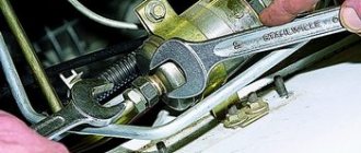
- Unscrew the main pipelines using 2 17mm wrenches;
- remove the gasket from the gas tank neck;
- unscrew the tank mount;
- move the tank to the side;
- remove the power and fuel level block;
- unscrew the fuel pump flange;
- remove the fuel pump filter;
- remove the tube from the pump after heating it;
- We take out the old pump and install a new one.
When installing the filter, do not hesitate to give it a good tap, otherwise it may fall off like mine. The fuel pump mesh on the VAZ injector is replaced if the old one is dirty or torn. Replacing the VAZ 2110 fuel pump mesh: description of the work. Its replacement is carried out in the same way. Usually it is sold complete with a fuel pump; if not, you will have to buy it, the price is 25 rubles.
Reassemble in reverse order. We heat the hose again in boiling water; if the mounting location of the old electric fuel pump does not allow the part to be properly secured, then we cut it off.
Important
When choosing, pay attention to performance and maximum pressure. Replacing a VAZ 2110 fuel pump: work procedure
I had Bosch 0 580 454 456 and replaced it with a close analogue of FR 453-453 from WEBER.
- OEM part number 21083-1139009-01;
- Installation of VAZ 2108 - 2115;
- Pressure - 580 kPa;
- Productivity - 60 l/min;
- Voltage - 13.5 V.
Consumption per 100 km at a speed of 120 is about 8 liters. Very pleased.
Replacing the fuel pump VAZ 2107 injector video:
Brake system VAZ 2104
- Brake fluid level sensor built into the expansion tank cap;
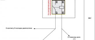
- Electronic mounting block in the engine compartment with terminal “A” to the generator;
- Ignition relay with negative terminal to ground;
- Ignition switch on the steering column;
- Indicator lamp on the instrument panel indicating low brake fluid level;
- Indicator lamp for activated parking brake.
Types of fuel pumps
Today there are various types of electric pumps, but the most common are:
- roller;
- gear;
- centrifugal;
Roller
The basis of such a pump is a rotor and rollers, which provide suction and fuel supply. The operation of the entire structure is based on increasing the volume of space between the rotor and the roller during operation. At such a moment of increase in volume, a difference in pressure is formed, fuel fills the resulting space. Further supply of fuel stops when this space is completely filled. The next step is to rotate the rotor and reduce the volume of space. This provides the required pressure, which causes the outlet opening to open, and the pumped dose of fuel enters the system.
Gear
Fuel suction in a gear pump is based on the movement of the internal gear relative to the external one. The internal gear is the rotor, while the second gear is external and is called the stator. The rotor rotates, and in its lateral teeth, when rotating, peculiar chambers are obtained. With their help, suction occurs and fuel is pumped.
The gear and roller pumps discussed above have such design features that they can only be placed in the fuel line. The most popular and widespread type of fuel pumps in modern cars are centrifugal pumps. They are characterized by low noise levels and provide the greatest uniformity of fuel supply.
Centrifugal
These pumps are located inside the fuel tank. The main element of this type of pump is an impeller with a large number of blades. Said impeller rotates inside the chamber. This chamber contains a suction and discharge valve. The rotation of the impeller blades results in fuel turbulence, which ensures its active suction, growth and maintenance of operating pressure in the fuel system.
Scheme for switching on headlights and fog lights
1 — block headlights; 2 — mounting block 2104; 3 — headlight switch in a three-lever switch; 4 — external lighting switch; 5 — rear fog light switch; 6 — rear lights; 7 - rear fog light circuit fuse; 8 — fog light indicator lamp, located in the indicator lamp block; 9 — indicator lamp for high beam headlights, located in the speedometer; 10 — ignition switch; P5 - headlight high beam relay; P6 - low beam headlight relay; A - view of the headlight plug connector: 1 - low beam plug; 2 — high beam plug; 3 — ground plug; 4 — side light plug; B - to terminal 30 of the generator; B — terminals of the rear light printed circuit board (numbering of terminals from the edge of the board): 1 — to ground; 2 — to the brake light lamp; 3 — to the side light lamp; 4 — to the fog light lamp; 5 — to the reversing light lamp; 6 - to the turn signal lamp.
Fuse and relay block VAZ-2104
On newer “sevens” a block with 17 fuses and 6 relays is installed. VAZ 2107 fuses on the “new” unit protect the following electrical circuits and devices:
- Reversing lamps, heater fan, rear window defroster warning lamp and relay, rear wiper motor and rear washer pump.
- Electric motor for front wipers.
- Reserve socket.
- Reserve socket.
- Power supply for heated rear window.
- Clock, cigarette lighter, power socket “carrying”.
- Signal and radiator fan.
- Turn signal lamps in emergency mode.
- “Fog lights” and a relay that regulates the voltage of the on-board network.
- Instrument panel lamps.
- Brake light bulbs.
- Right high beam headlight.
- Left high beam headlight, high beam warning lamp.
- Side lights (rear right, front left), license plate and engine compartment lighting.
- Side lights (rear left, front right), glove compartment and cigarette lighter lamps.
- Low beam (right lamp).
- Low beam (left lamp).
The block relays perform the following functions:
- Heated rear window relay.
- Headlight cleaner and washer relay.
- Signal relay.
- Cooling system electric fan relay.
- High beam relay.
- Low beam relay.
Troubleshooting the VAZ 2107 fuel pump
High-pressure fuel pump injection pump RE507959
Before checking the fuel pump, it is advisable to stock up on M8 bolts or other products of a similar diameter that can serve as plugs for fuel hoses.
To check the VAZ 2107 fuel pump, you must perform the following steps:
- Loosen the hose clamp that supplies gasoline to the carburetor and remove the hose from the fitting.
- Plug the fuel hose to prevent fuel from spilling out.
- Pump the fuel pump manual drive lever several times. If a stream of gasoline comes out of the outlet fitting, the fuel pump is working. If not, the check should continue.
- Loosen the inlet hose clamp, remove the hose and plug it in the same way as before.
- Close the inlet fitting with your finger and pump the hand drive lever several times. If there is a noticeable vacuum, the problem is not in the fuel pump. If the finger does not “stick”, it is necessary to remove and repair or replace the fuel pump.
Car modifications
VAZ-2104 . The basic version of the station wagon, with a carburetor engine from the VAZ-2105, 1.3 liters and 64 horsepower. Equipped with a 4-speed gearbox.
VAZ-21041 . A prototype of a station wagon, it was equipped with a carburetor engine from a VAZ-2101, with a volume of 1.2 liters and a power of 62 hp. Just like the base model, it was equipped with a 4-speed manual transmission.
VAZ-21042 . Export version, the steering wheel was located on the right. The car also received a carburetor engine from the VAZ-2103, with a volume of 1.5 liters and a power of 72 hp.
VAZ-21043 . The car was equipped with electrics and interior from a VAZ-2107, some copies had a VAZ-2106 interior. The carburetor engine was borrowed from the VAZ-2103. The gearbox was either 4 or 5 speed.
VAZ-21044 . An export model, equipped with a 1.7-liter VAZ-2107 engine with mono-injection, as well as a 5-speed gearbox.
VAZ-21045 . The export version with a 1.8-liter engine did not enter mass production.
VAZ-21045D . It was produced in small series since 1999, equipped with a VAZ-341 diesel engine with a volume of 1.52 liters and a power of 50 horsepower. The gearbox is 5-speed.
VAZ-21047 . A prototype with an engine starting from a penny. An improved version of the Four, it was equipped with a VAZ-2107 interior and a VAZ-2103 carburetor engine with a volume of 1.5 liters and a power of 72 hp. The gearbox was 5-speed. On export versions, the radiator grille was installed from the VAZ-2107.
VAZ-21048 . Diesel station wagon, with a 1.77-liter VAZ-343 engine. The gearbox is 5-speed.
VAZ-21041i . A car equipped with a VAZ-21067 injection engine. volume 1.6 liters. The gearbox is 5-speed. The electrical equipment and interior are from a VAZ-2107 car, and the front seats are from the Izhevsk hatchback IZH-2126.
VAZ-21041 VF . The interior, electrics and front seats are the same as the previous modification; the radiator grille is also borrowed from the VAZ-2107. It was equipped with a 1.5 liter injection engine from the VAZ-2103 and a 5-speed manual transmission.
The VAZ 2104 with rear-wheel drive and a station wagon body was produced from 1982 to 2012. The model was constantly improved: electrical equipment was changed, a fuel injection system, a five-speed gearbox and semi-sports front seats appeared. The VAZ 21043 modification was supplemented with a system for cleaning and heating the rear door window. The power supply system for individual vehicle components is quite simple.
Integrated power supply diagrams for VAZ 2104
All VAZ 2104 systems that consume electricity are switched over a single-wire line. The sources of electricity are the battery and the generator. The positive contact of these sources is connected to electrical devices, and the negative contact goes to the body (ground).
Electrical equipment of the VAZ 2104 is divided into three types:
- working equipment (battery, generator, ignition, starter);
- auxiliary operating equipment;
- light and sound alarm.
When the engine is turned off, all electrical equipment, including the starter, is powered by the battery. After the engine is started by the starter, the generator becomes the source of electricity. At the same time, it restores battery charge. The ignition system creates a spark discharge to ignite the fuel-air mixture entering the engine. The functions of the light and sound alarm include external lighting, interior lighting, turning on the headlights, and sounding a sound signal. Electrical circuits are switched through the ignition switch, which consists of an electrical contact unit and a mechanical anti-theft device.
The VAZ 2104 uses a 6ST-55P battery or similar. Synchronous generator 37.3701 (or G-222) is used as an alternating current source. This is a three-phase generator with electromagnetic excitation and a built-in rectifier unit based on silicon diodes. The voltage taken from these diodes powers the rotor winding and is supplied to the battery charge indicator lamp. On cars with a 2105–3701010 generator, this lamp is not used, and the battery charge level is monitored by a voltmeter. The generator is mounted on brackets in the right (in the direction of travel) front part of the engine compartment. The generator rotor is driven by a crankshaft pulley. The starter 35.3708 is attached to the clutch housing on the right side of the engine, protected by a heat-insulating shield from the exhaust system pipe and activated by an electromagnetic remote control relay.
The VAZ 2104 uses a contact ignition system, and in cars manufactured after 1987, a contactless ignition system. The contact system contains the following elements:
- a distributor-breaker designed to open the ignition coil circuit with a low voltage current and distribute high voltage pulses across the spark plugs;
- ignition coil, the main function of which is to convert low voltage current to high voltage current;
- spark plug;
- high voltage wires;
- ignition switch.
The contactless system consists of:
- a distribution sensor that supplies low voltage control pulses to the switch and distributes high voltage pulses across the spark plugs;
- a switch designed to interrupt the current in the low voltage circuit of the ignition coil in accordance with the signals of the distribution sensor;
- ignition coils;
- spark plugs;
- high voltage wires.
Current is constantly supplied to electrical circuits:
- sound signals;
- brake lights;
- cigarette lighter;
- interior lighting;
- portable lamp sockets;
- emergency light signaling.
To switch and protect electrical appliances from voltage surges, in a special niche in the engine compartment there is a mounting block with fuses and relays, the purpose of which is schematically indicated on the cover of the block. The standard unit can be removed, the board can be replaced, or its conductive paths can be restored.
On the dashboard of the VAZ 2104 there are power keys:
- external lighting fixtures;
- fog lights;
- heated rear window;
- interior heating.
The light alarm button is located on the protective cover of the steering column shaft, and under the column there are switches for low and high beams, turn signals, wipers and windshield washer.
Electrical diagram of VAZ 21043 and 21041i (injector)
Models VAZ 21043 and 21041i (sometimes incorrectly designated as 21047) have identical power supply circuits. All electrical equipment of these cars is similar to that of the VAZ 2107.
The export version of the VAZ 2104 and VAZ 21043 additionally includes a wiper and heated rear window. Since 1994, this scheme has become the standard for all produced fours. After the appearance of injection models, the scheme was slightly changed. This was also due to the appearance of a five-speed gearbox, electrical equipment and interior from the VAZ 2107, as well as electronic components that control engine operation.
Device
The DAAZ carburetor, developed by analogy with the product of the Italian brand Weber, is designed to dose the gas-air mixture in all engine operating modes without the participation of electronics. It consists of three main parts:
- covers with semi-automatic starting system;
- main or middle block with camera;
- additional or lower block with throttle valves.
The device cover includes important parts of the carburetor: flaps, a fitting for connecting a gasoline supply hose, a filter mesh, a needle float, an econostat tube, and an accelerator pump. The upper part of the carb is connected to the main block using several screws (M5).
The middle block consists of the main chamber, diffusers, jets, and a sprayer (helicopter). All the necessary channels responsible for certain engine operating modes are installed here.
The lower or additional block is equipped with throttles and adjusting screws, thanks to which it is possible to adjust the quality and quantity of the sprayed combustible mixture. There are also many different output channels available here. Like the upper part, it is connected to the main unit via screws.
It is easier to consider the carburetor design by looking at the operation of individual subsystems:
- A special place in the carburetor is occupied by the starting device system or SPU. It comes into operation when the engine starts. It is activated due to the vacuum created as a result of the movement of the cable when the diffuser opens. The SPU closely interacts with the gas pedal;
- Idle system. Its functions are clear by its name. On Weber it is of the classic type, on Ozone it is autonomous and works independently of the carburetor. On standard systems there is a special calibration screw that adjusts the throttle or air. It makes it possible to increase or decrease the number of idle speeds. There is also a mixture quality screw located in a different place, in a recess. By rotating it, you can supply the engine with exactly the amount of gasoline it needs;
- A transition system responsible for a smooth transition from idle to operation of the main jets. There is also a separate jet, which can also be attributed to this system. It stabilizes engine operation at high speeds;
- Main metering system based on the operation of the emulsion tube, fuel nozzle and chokes. It is in this mode that it is possible to open both throttles and the maximum speed of the car;
- Accelerator pump system. It controls the mixture, preventing air from entering more than normal. This makes it possible to avoid throttle failures during sudden car starts from a standstill and other maneuvers;
- Econostat that increases engine thrust at maximum speed. Consists of three jets: fuel, emulsion and air;
- A float mechanism system that maintains a constant fuel level in the chamber. Equipped with an adjustable needle valve. When the fuel in the chamber decreases, the float moves down, the valve opens and gasoline from the tank begins to flow through the fitting.
Switching in the VAZ 2104 interior
In relation to the circuits taken as a basis from the VAZ 2105 and 2107, the electrical equipment of the interior of the VAZ 2104 and 21043 has been supplemented:
- rear window wiper, which is activated by a button on the dashboard;
- courtesy lamp for the rear part of the body.
The rear window wiper consists of a gear motor, a lever and a brush. The gearmotor, like the windshield washer motor, can be disassembled. The electrical circuit of the cleaner and washer is protected by fuse No. 1, and the lamp circuit is protected by fuse No. 11. Power is supplied to the lights, heater and rear window wiper using a wiring harness.
Diagnostics
The primary conclusion whether the fuel pump is working or not can be assessed by ear when the ignition is turned on. If you can’t hear a quiet buzzing sound from behind, then you need to check the voltage supply to the gas tank block and later draw a conclusion about its malfunction.
Add to the group on VK https://vk.com/autovaz2107 Donation to pay for the web: WEBMONEY- R394885703159 YANDEX.
You can check the serviceability of the fuel pump using the MTL-2 pressure gauge; this is the most correct way. You can somewhat roughly estimate the pressure using air pressure gauges to check tire pressure. To do this, screw a rubber hose to the sensor and connect it to the fuel system.
The pressure of the VAZ 2107 injector fuel pump when the ignition is on should be 4.0 atmospheres, and when the ignition is running 2.8-3.2. In reality, the pump pressure is different and was slightly less, but this may be an error in the pressure gauge.
The carburetor pump is checked by setting the camshaft position by cranking the engine so as to ensure free movement of the pump foot. The hose is unscrewed from the carburetor or filter and the presence of fuel supply is determined by pressing the foot.
Replacement of electrical wiring of VAZ 2104
If there is a failure in the power supply to electrical equipment, you should first check the integrity of the electrical circuit. To do this you need:
- De-energize the area being tested by disconnecting the negative terminal of the battery or the corresponding fuse.
- Connect the contacts of the multimeter to the ends of the problem section of the circuit, and one of the probes to ground.
- If there are no readings on the multimeter display, there is a break in the circuit.
- The wiring is replaced with a new one.
Selection of wires and replacement of wiring is carried out according to the VAZ 2104 power supply diagram. In this case, standard components or components from another model with suitable characteristics are used.
Video: replacing wiring, fuses and relays of classic VAZ models
To replace the wiring, the front part of the cabin is disassembled. Wires of insufficient length are extended, and connections are soldered and insulated.
Video: replacing electrical wiring in the cabin and under the hood
It is almost impossible to completely replace the electrical wiring of a VAZ 2104 with your own hands. If such a situation arises, it is better to contact a car service.
Video: repair of electrical wiring of injection VAZ 2107
TNND device
TNND consists of:
- Drive shaft;
- A rotor with a certain number of blades;
- Stator;
- Distribution disk;
- Adjustable drive gear;
- Connection couplings.
Low pressure fuel pump design
When the rotor begins to move, its blades begin to move closer to the stator and, under the influence of centrifugal force, certain chambers appear. Since there is a certain voltage inside, the fuel from these chambers is sent directly to the fuel injection pump. For this purpose, special channels in the distribution disk are used. In this case, a small amount of fuel is directed to the pressure reduction valve if the pressure is created greater than that set by the system.
Since both devices are inextricably linked, to maintain the necessary conditions, a fuel drain choke (in the form of a nozzle) screwed into the high-pressure pump is used. Thus, the design of this part makes it possible to create the necessary conditions in the chambers depending on the speed of the drive shaft. This design is suitable for diesel engines, but there are other types, which will be discussed further.
Main malfunctions of the electrical equipment of the VAZ 2104
The main faults in electrical wiring are short circuits and broken wires. When a short circuit occurs, fuses blow, relays and devices fail. Sometimes a fire may even occur. When a wire breaks, the nodes to which this wire is connected stop working.
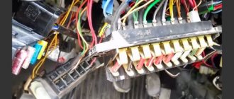
Mounting block
All electrical equipment is connected through fuses located in the mounting block and providing protection for this equipment in case of a short circuit. On the VAZ 2104, mounting blocks made in the Russian Federation or Slovenia are installed. The latter cannot be disassembled and cannot be repaired.
Table: fuses in the VAZ 2104 mounting block
| Fuse (rated current) | Protected circuit equipment |
| 1 (8A) | Reversing rear lights; Heater motor; Warning lamp, rear door glass heating relay. |
| 2 (8A) | Electric motors for windshield wiper and washer; Electric motors for headlight cleaners and washers; Windshield wiper relay. Relay for headlight cleaners and washers (contacts). |
| 3 (8A) | Spare. |
| 4 (8A) | Spare. |
| 5 (16A) | Heating element and rear door glass heating relay. |
| 6 (8A) | Cigarette lighter; Socket for portable lamp; Watch; Signal lights for open front doors. |
| 7 (16A) | Sound signals and signal activation relays; Engine cooling fan electric motor and electric motor switching relay (contacts). |
| 8 (8A) | Switch and relay-breaker for direction indicators in emergency mode. |
| 9 (8A) | Generator voltage regulator (on vehicles with a GB222 generator). |
| 10 (8A) | Turn indicators when turned on and corresponding warning lamp; Fan motor activation relay (winding); Control devices; Battery charge indicator lamp; Indicator lamps for fuel reserve, oil pressure, parking brake and brake fluid level; Parking brake warning light relay; Carburetor solenoid valve control system. |
| 11 (8A) | Rear brake lights; Interior lighting. |
| 12 (8A) | Right headlight (high beam); Coil of the relay for turning on the headlight cleaners (with the high beams on). |
| 13 (8A) | Left headlight (high beam); Indicator lamp for turning on the high beam headlights. |
| 14 (8A) | Left headlight (side light); Right rear light (side light); License plate lights; Engine compartment lamp; Indicator lamp for turning on the side light. |
| 15 (8A) | Right headlight (side light 2105); Left rear light (side light); Cigarette lighter illumination; Instrument lighting; Illuminated glove compartment. |
| 16 (8A) | Right headlight (low beam); Coil of the relay for turning on the headlight cleaners (with the low beam on). |
| 17 (8A) | Left headlight (low beam 2107). |
Connections of the VAZ 2104 mounting block
In addition to fuses, the mounting block contains six relays.
In addition, in the figure:
- the numbers under the letter A correspond to the number of the plug in the mounting block blocks;
- the numbers next to the letter Ш indicate the number of the block and the number of the plug;
- The plugs of blocks without color markings are marked in brown.
Video: repairing the fuse box of classic VAZ models
When replacing fuses and repairing the mounting block, you must:
- disconnect the negative terminal of the battery with the ignition off;
- when replacing a fuse, identify the cause of its blown;
- Do not use fuses of increased rating to avoid burning out the corresponding board tracks.
Video: restoration of the tracks of the VAZ 2105 mounting block
Connecting low, high and fog lights
The circuit for switching on the headlights and fog lights in the rear lights of the VAZ 2104 is similar to the corresponding circuits for the VAZ 2105 and VAZ 2107.
Fuel supply system
The distributed injection system in the injection VAZ 2104 involves supplying fuel to each cylinder with a separate nozzle. This system combines the power and ignition subsystems, controlled using the “January-5.1.3” controller.
The controller, which receives information about engine operating parameters, identifies all faults and, if necessary, issues a Check Engine signal. The controller itself is mounted on a bracket in the cabin behind the glove box.
Switches located on the steering column
The turn signal switches are located under the steering column, and the hazard warning light button is on the column itself. The blinking of the direction indicators with a frequency of 90±30 times per minute is provided by the alarm relay at a voltage of 10.8–15.0 V. If one of the direction indicators malfunctions, the blinking frequency of the other indicator and warning lamp doubles.
Electric windows
Some car owners install electric windows on their VAZ 2104.
The features of installing such window lifters on a VAZ 2104 are determined by the size and design of the front door windows. Unlike other classic VAZ models, the front doors of the four (like the VAZ 2105 and 2107) do not have rotary windows. Fully lowered front windows take up more space inside the door frame.
Video: installation of Forward window lifters on the front doors of a VAZ 2107
When choosing electric window regulators, you should ensure that there is free space for installing the electric motor and drive mechanism.
Adjusting the float system of the carburetor of VAZ cars
If you remove the carburetor cover, the float chamber protrudes in front of us. This is where you can start making adjustments. The free play of the float is 6.5 mm on one side and 14 mm on the other. The free play of the float can be adjusted using a special template placed vertically in the chamber. This will cause the float to lightly touch, but not press, the valve ball.
If the free play of the float is less than 6.5 mm, then it is necessary to carefully bend the tongue of the needle valve, marked in the figure with the letter “A”.
Next, you can begin to adjust the needle valve that supplies fuel to the float chamber. When the float rises, the fuel supply decreases, and when you sharply press the accelerator pedal and open the throttle, the fuel supply increases and the float drops.
Next, we will adjust the degree of deflection of the float in the other direction. To do this, you need to move the float as far as possible from the cover and, using a 14 mm thick template, check the distance. If the distance of the float from the cover does not correspond to 14 mm, then it is necessary to stop the float mounting bracket so that it does not exceed the required value.
After adjustment, the free play of the float should be about 8 mm. Adjusting the carburetor of VAZ 2104, 2105, 2106, 2107 also involves checking and cleaning fuel strainers and filters.