Back
Fault codes for VAZ 21214 i
To read the codes of faults that have occurred, you can do without the device. At the driver's left knee, behind the injection system fuse block (there are four places for fuses, but there should only be three in order of increasing distance from the driver - two blue - for 15 amperes and one red - for 10 amperes), there is a diagnostic block. With the ignition off, you need to close the two distant contacts in the top row (if you look closely at the diagnostic block, there really aren’t that many “real” contacts there). Then turn on the ignition, and the CHECK ENGINE light should start blinking. The meaning of her blinking is as follows: all codes are two-digit; number of blinks between pauses - number; each code is repeated three times; First, code 12 should be issued. This means the diagnostic system is working properly. Next, codes for the faults that occurred are displayed in ascending order. The sequence of codes ends with code 12. I don’t know the correct way to clear the memory of codes of faults that have occurred, so I suggest disconnecting the battery to clear the memory. The fact is that all malfunctions that have ever occurred are remembered and are not cleared after they are eliminated. On the other hand, the injection system on the VAZ-21214i is self-learning, including for a specific driver, and after turning off the power, the system forgets everything it has learned. True, it will quickly restore lost knowledge, so I don’t see any particular crime in turning off the power.
(Also some codes are presented here)
DIAGNOSTIC CODES FOR CONTROLLER M 7.9.7
| Code | Description |
| P0102 | Mass Air Flow Sensor Circuit Low Signal |
| P0103 | Mass Air Flow Sensor Circuit High Signal |
| P0112 | Intake Air Temperature Sensor Circuit Low Signal |
| P0113 | Intake Air Temperature Sensor Circuit High Signal |
| P0116 | Coolant temperature sensor circuit, signal out of range |
| P0117 | Coolant Temperature Sensor Circuit Low Signal |
| P0118 | Coolant Temperature Sensor Circuit High |
| P0122 | Throttle Position Sensor Circuit Low Signal |
| P0123 | Throttle Position Sensor Circuit High |
| P0130 | The oxygen sensor before the converter is faulty |
| P0131 | Oxygen sensor circuit to converter, low output level |
| P0132 | Oxygen sensor circuit to converter, high output signal level |
| P0133 | Oxygen sensor circuit to the converter, slow response to changes in mixture composition |
| P0134 | The oxygen sensor circuit to the converter is inactive |
| P0135 | The oxygen sensor after the converter is faulty |
| P0136 | The oxygen sensor after the converter is faulty |
| P0137 | Oxygen sensor circuit after the converter, low signal level |
| P0138 | Oxygen sensor circuit after the converter, high signal level |
| P0140 | The oxygen sensor circuit after the converter is inactive |
| P0141 | Oxygen sensor after converter, heater faulty |
| P0171 | Fuel system too lean |
| P0172 | Fuel system too rich |
| P0201 P0202 P0203 P0204 | Cylinder 1 injector (2,3,4), control target break |
| P0261 P0264 P0267 P0270 | Cylinder 1 injector (2,3,4), control target short to ground |
| P0262 P0265 P0271 | Cylinder 1 injector (2,3,4), control circuit shorted to on-board network |
| P0300 | Random/multiple misfires detected |
| P0301 P0302 P0303 P0304 | Cylinder 1 (2,3,4), misfire detected |
| P0327 | Knock Sensor Circuit Low Signal |
| P0328 | Knock Sensor Circuit High Signal |
| P0335 | Crankshaft position sensor circuit is faulty |
| P0336 | Crankshaft position sensor circuit, signal out of range |
| P0340 | Camshaft position sensor is faulty |
| P0342 | Camshaft Position Sensor Circuit Low Signal |
| P0343 | Camshaft Position Sensor Circuit High Signal |
| P0422 | Neutralizer efficiency below threshold |
| P0441 | Gasoline vapor recovery systems, incorrect air flow through the canister purge valve |
| P0480 | Fan relay 1 control circuit faulty |
| P0600 | Vehicle speed sensor is faulty |
| P0606 | Idle system, low engine speed |
| P0507 | Idle system, high engine speed |
| P0560 | On-board network voltage is below the system operability threshold |
| P0562 | On-board voltage, low level |
| P0663 | On-board voltage, high level |
| P0601 | ECM checksum error |
| P0615 | Additional starter relay, control circuit open |
| P0616 | Additional starter relay, control circuit short to ground |
| P0617 | Additional starter relay, control circuit closed to on-board network |
| P1135 | Oxygen sensor preheater, control circuit faulty |
| P1141 | Oxygen sensor heater after converter, control circuit faulty |
| P1386 | ECM knock detection channel error |
| P1410 | Canister purge valve, control circuit shorted to on-board network |
| P1425 | Canister purge valve, control circuit short to ground |
| P1426 | Canister purge valve, control circuit open |
| P1501 | Fuel pump relay, control circuit short to ground |
| P1502 | Fuel pump relay, control circuit shorted to on-board network |
| P1513 | Idle speed control, control circuit short to ground |
| P1514 | Idle air control control circuit faulty |
| P1541 | Fuel pump switch, control circuit open |
| P1570 | Immobilizer, circuit faulty |
| P1602 | HUD controller loss of supply voltage |
| P1606 | Rough road sensor circuit, signal out of acceptable range |
| P1616 | Rough Road Sensor Circuit Low Signal |
| P1617 | Rough Road Sensor Circuit High Signal |
| P1640 | ECM EEPROM read-write error |
Error codes Niva 21214 injector
Back Fault codes for VAZ 21214 i
To read the codes of faults that have occurred, you can do without the device. At the driver's left knee, behind the injection system fuse block (there are four places for fuses, but there should only be three in order of increasing distance from the driver - two blue - for 15 amperes and one red - for 10 amperes), there is a diagnostic block. With the ignition off, you need to close the two distant contacts in the top row (if you look carefully at the diagnostic block, there really aren’t that many “real” contacts there). Then turn on the ignition, and the CHECK ENGINE light should start blinking. The meaning of her blinking is as follows: all codes are two-digit; number of blinks between pauses - number; each code is repeated three times; First, code 12 should be issued. This means the diagnostic system is working properly. Next, codes for the faults that occurred are displayed in ascending order. The sequence of codes ends with code 12. I don’t know the correct way to clear the memory of codes of faults that have occurred, so I suggest disconnecting the battery to clear the memory. The fact is that all malfunctions that have ever occurred are remembered and are not cleared after they are eliminated. On the other hand, the injection system on the VAZ-21214i is self-learning, including for a specific driver, and after turning off the power, the system forgets everything it has learned. True, it will quickly restore lost knowledge, so I don’t see any particular crime in turning off the power.
(Also some codes are presented here)
DIAGNOSTIC CODES FOR CONTROLLER M 7.9.7
| Code | Description |
| P0102 | Mass Air Flow Sensor Circuit Low Signal |
| P0103 | Mass Air Flow Sensor Circuit High Signal |
| P0112 | Intake Air Temperature Sensor Circuit Low Signal |
| P0113 | Intake Air Temperature Sensor Circuit High Signal |
| P0116 | Coolant temperature sensor circuit, signal out of range |
| P0117 | Coolant Temperature Sensor Circuit Low Signal |
| P0118 | Coolant Temperature Sensor Circuit High |
| P0122 | Throttle Position Sensor Circuit Low Signal |
| P0123 | Throttle Position Sensor Circuit High |
| P0130 | The oxygen sensor before the converter is faulty |
| P0131 | Oxygen sensor circuit to converter, low output level |
| P0132 | Oxygen sensor circuit to converter, high output signal level |
| P0133 | Oxygen sensor circuit to the converter, slow response to changes in mixture composition |
| P0134 | The oxygen sensor circuit to the converter is inactive |
| P0135 | The oxygen sensor after the converter is faulty |
| P0136 | The oxygen sensor after the converter is faulty |
| P0137 | Oxygen sensor circuit after the converter, low signal level |
| P0138 | Oxygen sensor circuit after the converter, high signal level |
| P0140 | The oxygen sensor circuit after the converter is inactive |
| P0141 | Oxygen sensor after converter, heater faulty |
| P0171 | Fuel system too lean |
| P0172 | Fuel system too rich |
| P0201 P0202 P0203 P0204 | Cylinder 1 injector (2,3,4), control target break |
| P0261 P0264 P0267 P0270 | Cylinder 1 injector (2,3,4), control target short to ground |
| P0262 P0265 P0271 | Cylinder 1 injector (2,3,4), control circuit shorted to on-board network |
| P0300 | Random/multiple misfires detected |
| P0301 P0302 P0303 P0304 | Cylinder 1 (2,3,4), misfire detected |
| P0327 | Knock Sensor Circuit Low Signal |
| P0328 | Knock Sensor Circuit High Signal |
| P0335 | Crankshaft position sensor circuit is faulty |
| P0336 | Crankshaft position sensor circuit, signal out of range |
| P0340 | Camshaft position sensor is faulty |
| P0342 | Camshaft Position Sensor Circuit Low Signal |
| P0343 | Camshaft Position Sensor Circuit High Signal |
| P0422 | Neutralizer efficiency below threshold |
| P0441 | Gasoline vapor recovery systems, incorrect air flow through the canister purge valve |
| P0480 | Fan relay 1 control circuit faulty |
| P0600 | Vehicle speed sensor is faulty |
| P0606 | Idle system, low engine speed |
| P0507 | Idle system, high engine speed |
| P0560 | On-board network voltage is below the system operability threshold |
| P0562 | On-board voltage, low level |
| P0663 | On-board voltage, high level |
| P0601 | ECM checksum error |
| P0615 | Additional starter relay, control circuit open |
| P0616 | Additional starter relay, control circuit short to ground |
| P0617 | Additional starter relay, control circuit closed to on-board network |
| P1135 | Oxygen sensor preheater, control circuit faulty |
| P1141 | Oxygen sensor heater after converter, control circuit faulty |
| P1386 | ECM knock detection channel error |
| P1410 | Canister purge valve, control circuit shorted to on-board network |
| P1425 | Canister purge valve, control circuit short to ground |
| P1426 | Canister purge valve, control circuit open |
| P1501 | Fuel pump relay, control circuit short to ground |
| P1502 | Fuel pump relay, control circuit shorted to on-board network |
| P1513 | Idle speed control, control circuit short to ground |
| P1514 | Idle air control control circuit faulty |
| P1541 | Fuel pump switch, control circuit open |
| P1570 | Immobilizer, circuit faulty |
| P1602 | HUD controller loss of supply voltage |
| P1606 | Rough road sensor circuit, signal out of acceptable range |
| P1616 | Rough Road Sensor Circuit Low Signal |
| P1617 | Rough Road Sensor Circuit High Signal |
| P1640 | ECM EEPROM read-write error |
Video
Intended for non-commercial use. All rights belong to JSC AvtoVAZ. The section presenters are not responsible for any inaccuracies or inconsistencies contained in this guide.
Attention!
Due to the fact that the quality of the copy that was scanned was unacceptable for text recognition, it was decided to publish the book in the form of pictures and in three versions: a print version (multi-page .tiff file with G4 compression, size 4.8Mb) and an on-line reference version for review from the site. The size of each image in the on-line version is from 25 to 80Kb. The printable version must be downloaded to your computer (by right-clicking on the link below and selecting Save Target As) and printed on a printer with a resolution of at least 300dpi. As an option, you can download a self-extracting archive of the on-line version (volume 6.1 Mb).
Online consultation
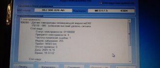
Code Explanation P0030 Heater of the oxygen sensor to the neutralizer, control circuit open P0031 Heater of the oxygen sensor to the neutralizer, short circuit of the control circuit to ground P0032 Heater of the oxygen sensor to the neutralizer, short circuit of the control circuit to the board. network P0036 Oxygen sensor heater after the converter, control circuit open P0037 Oxygen sensor heater after the converter, control circuit short to ground P0038 Oxygen sensor heater after the converter, control circuit short to board. network P0102 Mass air flow sensor circuit, low signal level P0103 Mass air flow sensor circuit, high signal level P0112 Air temperature sensor circuit, low signal level P0113 Air temperature sensor circuit, high signal level P0116 Coolant temperature sensor circuit, signal output out of range range P0117 Coolant temperature sensor circuit, low signal level P0118 Coolant temperature sensor circuit, high signal level P0122 Throttle position sensor circuit, low signal level P0123 Throttle position sensor circuit, high signal level P0130 Oxygen sensor to the converter is faulty P0131 Sensor circuit oxygen sensor before the converter, low output signal P0132 Oxygen sensor circuit before the converter, high output signal P0133 Oxygen sensor circuit before the converter, slow response to changes in mixture composition P0134 Oxygen sensor circuit before the converter is inactive P0136 Oxygen sensor after the converter is faulty P0137 Oxygen sensor circuit after the converter converter, low signal level P0138 Oxygen sensor circuit after the converter, high signal level P0140 Oxygen sensor circuit after the converter is inactive P0141 Oxygen sensor after the converter, heater faulty P0171 Fuel supply system too lean P0172 Fuel supply system too rich P0201 Cylinder 1 injector, control circuit open P0202 Injector cylinder 2, control circuit open P0203 Cylinder 3 injector, control circuit open P0204 Cylinder 4 injector, control circuit open P0217 Engine temperature above permissible P0230 Fuel pump relay circuit malfunction P0261 Cylinder 1 injector, control circuit short to ground P0263 Injector 1 driver malfunction P0264 Force unka cylinder 2, control circuit short to ground P0266 Injector driver 2 fault P0267 Cylinder 3 injector, control circuit short to ground P0269 Injector driver 3 fault P0270 Cylinder 4 injector, control circuit short to ground P0262 Cylinder 1 injector, control circuit short to the on-board network P0265 Injector ka Cylinder 2 control circuit short to on-board power P0268 Cylinder 3 injector control circuit short to on-board power P0271 Cylinder 4 injector control circuit short to on-board power P0272 Injector 4 driver malfunction P0300 Random/multiple misfire detected P0301 Cylinder 1 misfire detected P0302 Cylinder 2 misfire detected P0303 Cylinder 3 misfire detected P0304 Cylinder 4 misfire detected P0326 Knock sensor circuit out of range P0327 Knock sensor circuit low P0328 Knock sensor circuit high P0335 Sensor circuit crankshaft position sensor faulty P0336 Crankshaft position sensor circuit, signal out of acceptable range P0337 Crankshaft position sensor, short to ground P0338 Crankshaft position sensor, open circuit P0342 Phase sensor circuit, low signal level P0343 Phase sensor circuit, high signal level P0346 Sensor circuit phases, signal output from the permissible range P0351 Ignition coil of cylinder 1 (1-4), open circuit of the control circuit P0352 Ignition coil of cylinder 2 (2-3), open circuit of the control circuit P0353 Ignition coil of cylinder 3, open circuit of the control circuit P0354 Ignition coil of cylinder 4, open circuit open control circuit P0363 Misfire detected, fuel supply is turned off in idle cylinders P0422 Converter efficiency below threshold P0441 Gasoline vapor recovery system, incorrect air flow through the canister purge valve P0444 Canister purge valve, open control circuit P0445 canister purge valve, control circuit short to ground or on-board network P0480 Fan relay, control circuit open P0481 Cooling fan 2 circuit malfunction P0500 Vehicle speed sensor faulty P0506 Idle system, low engine speed P0507 Idle system, high engine speed P0511 Idle speed regulator, control circuit faulty P0560 On-board network voltage lower system performance threshold P0562 On-board network voltage, low level P0563 On-board network voltage, high level P0601 Engine control system controller, ROM checksum error P0615 Additional starter relay, control circuit open P0616 Additional starter relay, control circuit short to ground P0617 Additional starter relay, open circuit short circuit of the control circuit to the on-board network P0627 Fuel pump relay, open circuit of the control circuit P0628 Fuel pump relay, short circuit of the control circuit to ground P0629 Fuel pump relay, short circuit of the control circuit to the on-board network P0645 Relay of the air conditioner compressor clutch, open circuit of the control circuit P0646 Relay of the air conditioning compressor clutch, short circuit of the control circuit to ground P0647 Air conditioning compressor clutch relay, control circuit shorted to board. network P0650 Malfunction indicator lamp, control circuit faulty P0654 Instrument cluster tachometer, control circuit faulty P0685 Main relay, control circuit open P0686 Main relay, control circuit shorted to ground P0687 Main relay, control circuit shorted to the on-board network P0691 Fan relay, control circuit shorted to ground P0692 Fan relay, control circuit short to on-board power supply P1102 Oxygen sensor heater resistance low P1115 Oxygen sensor heater faulty circuit P1123 Idle rich P1124 Idle lean P1127 Idle rich P1128 Part Load rich P1128 Idle lean Partial Load P1135 Oxygen sensor heater circuit 1 open, short circuit P1136 Rich in Light Load mode P1137 Lean mixture in Light Load mode P1140 Measured load differs from calculation P1141 Oxygen sensor heater 1 after converter fault P1171 CO potentiometer low level P1172 CO potentiometer high level P1301 Cylinder 1, converter critical misfire detected P1302 Cylinder 2, converter critical misfire detected P1303 Cylinder 3, converter critical misfire detected P1304 Cylinder 4, converter critical misfire detected P1386 Knock Channel Test Error P1410 Canister purge valve control circuit short circuit to +12V P1425 Canister purge valve control circuit short circuit to ground P1426 Canister purge valve control circuit open circuit P1500 Fuel pump relay control circuit open P1501 Short to ground fuel pump relay control circuit P1502 Short circuit to +12V control circuit relay fuel pump P1509 Overload of the idle speed regulator control circuit P1513 Idle speed regulator circuit short circuit to ground P1514 Idle speed regulator circuit short circuit to +12V, open P1541 Fuel pump relay control circuit open P1570 Immobilizer, circuit faulty P1602 Engine management system controller, loss of supply voltage P160 6 Rough road sensor circuit, signal out of acceptable range P1616 Rough road sensor circuit, low signal level P1617 Rough road sensor circuit, high signal level P2301 Ignition coil of cylinder 1 (1-4), short circuit of the control circuit to the board. network P2303 Ignition coil of cylinder 2 (2-3), control circuit shorted to board. network P2305 Ignition coil of cylinder 3, control circuit shorted to board. network P2307 Ignition coil of cylinder 4, control circuit shorted to board. net
How self-diagnosis of Niva Chevrolet is carried out and the main error codes
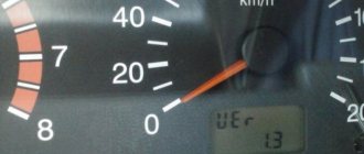
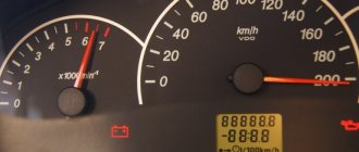
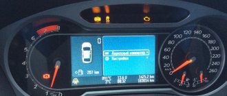
Few people know that the Chevrolet Niva has a self-diagnosis function that produces basic error codes that can be used to quickly find and fix vehicle problems. It is not difficult to carry out this procedure yourself; just press the odometer button firmly and turn on the ignition at the same time. The arrows on the speedometer will creep up, after pressing again, an information message about the firmware version will be displayed, and the next time, all error codes will appear on the monitor, naturally, if there are malfunctions in the car.
GAZ error codes
| Error code | Decoding the code |
| 12 | The unit self-diagnosis mode is turned on (short circuit of the L-line to ground) |
| 13,14 | Low/High signal level of air flow sensor |
| 15,16 | Low / High signal level of the absolute pressure sensor |
| 17,18 | Low/High signal level of air temperature sensor |
| 19 | Engine overheating (coolant temperature < 105 o C) |
| 21,22 | Low/High Coolant Temperature Sensor Signal Level |
| 23,24 | Low/High Throttle Sensor Signal |
| 25,26 | Low/High voltage level on board network |
| 27..29 | Angle synchronization sensor malfunction |
| 31,32 | Low/High Signal Level 1 CO Adjustment |
| 33,34 | Low/High signal level 2 CO adjustments |
| 35,36 | Low / High signal level of 1 LAMDA probe |
| 37,38 | Low/High signal level of 2 LAMDA probes |
| 41,42 | Knock sensor circuit 1/2 malfunction |
| 43,44 | Low / High signal level of the recirculation valve sensor |
| 45,46 | Low/High signal level of the canister valve sensor |
| 47,48 | Low/High Power Steering Sensor Signal Level |
| 51,52 | Control unit 1 / 2 faulty |
| 53 | Angle synchronization sensor malfunction |
| 54 | Camshaft position sensor malfunction |
| 55 | Speed sensor malfunction |
| 61 | Resetting the control unit |
| 62 | RAM fault |
| 63 | ROM malfunction |
| 64,65 | EEPROM read/write error |
| 66 | Error reading control unit identification code |
| 67..69 | Immobilizer error |
| 71,72 | Low/High Idle Speed |
| 73,74 | Rich / Lean mixture regulator by 1L probe |
| 75,76 | Rich / Lean mixture regulator by 2L probe |
| 79 | EGR control fault by SEGR |
| 81..88 | Maximum displacement of the ignition timing by detonation 1 / 2 / 3 / 4 / 5 / 6 / 7 / 8 cylinder |
| 91..98 | Ignition circuit short circuit 1/2/3/4/5/6/7/8 cylinder |
| 131,132,133 | Injector 1 Short circuit / Open circuit / Short circuit to ground |
| 134,135,136 | Injector 2 Short circuit / Open circuit / Short circuit to ground |
| 137,138,139 | Injector 3 Short circuit / Open circuit / Short circuit to ground |
| 141,142,143 | Injector 4 Short circuit / Open circuit / Short circuit to ground |
| 144,145,146 | Injector 5 Short circuit / Open circuit / Short circuit to ground |
| 147,148,149 | Injector 6 Short circuit / Open circuit / Short circuit to ground |
| 151,152,153 | Injector 7 Short circuit / Open circuit / Short circuit to ground |
| 154,155,156 | Injector 8 Short circuit / Open circuit / Short circuit to ground |
| 157,158,159 | Trigger Injector Short Circuit/Open/Short to Ground |
| 161,162,163 | Winding 1 auxiliary air regulator Short circuit / Open circuit / Short circuit to ground |
| 164,165,166 | Winding 2 auxiliary air regulator Short circuit / Open circuit / Short circuit to ground |
| 167,168,169 | Fuel pump relay circuit Short circuit / Open circuit / Short circuit to ground |
| 171,172,173 | Recirculation valve Short circuit / Open circuit / Short circuit to ground |
| 174,175.176 | Canister Purge Valve Short Circuit/Open/Short to Ground |
| 177,178,179 | Main Relay Short Circuit/Open/Short to Ground |
| 181,182,183 | CheckEngine Lamp Short Circuit/Open/Short to Ground |
| 184,185,186 | Tachometer Circuit Short / Open / Short to Ground |
| 187,188,189 | Fuel Flow Circuit Short / Open / Short to Ground |
| 191,192,193 | A/C Relay Circuit Short/Open/Short to Ground |
| 194,195,196 | Fan Relay Circuit Short / Open / Short to Ground |
| 197,198,199 | EPHH valve circuit Short circuit / Open circuit / Short circuit to ground |
| 231..238 | Open ignition circuit 1 / 2 / 3 / 4 / 5 / 6 / 7 / 8 cylinder |
| 241..248 | Short circuit to ground in ignition circuit 1/2/3/4/5/6/7/8 cylinder |
| 251,252,253 | Burning mass fuel flow sensor Short circuit / Open circuit / Short circuit to ground |
You can also list the fault codes.
Errors VAZ 21214 NIVA
Since the purchase of a new Niva, the breakdown light on the panel has been lit.
Then I decided to figure out why it was burning.
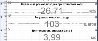
Bosch controller 7.9.7+
Initially, the Kulibins were tinkering with the wiring, which is why questions arose
They brought the BC and read the mistakes.
1. 0480 – Malfunction of the cooling fan relay control circuit No. 1.
I started to figure it out. According to the primer, the control on the fan relay comes from the controller, but in fact the plus is taken from the battery and the fans are turned on thanks to the temperature sensor, i.e. The fans have no connection with the controller in any way. They successfully turn on as a pair when the temperature reaches 92C (+- a couple of degrees) and cool the motor to 85C (+-). The engine temperature is maintained at normal levels.
Does the absence of any connection between the fans and the controller affect the operation of the engine? The error will clearly be displayed because the brains don't see the fans at all.
He seemed to describe the problem in sufficient detail to the best of his knowledge of car electricals.
2. 1135 – Oxygen sensor to the converter, heater is faulty
3. 0135 – Heater of the oxygen sensor before the converter, control circuit is faulty
These two errors only appear when it is cold, i.e. until the engine is warmed up. When hot, these errors disappear. Chip (the connection of the oxygen sensor with the main wiring checked everything in good order)
It turns out that the oxygen sensor heater does not work or is not present in this oxygen sensor at all
How to further diagnose these errors. ?
How does an oxygen sensor that doesn't work when cold affect engine performance? and when the engine warms up it works properly.
Thank you in advance for any information on solving the problem.
Does the absence of any connection between the fans and the controller affect the operation of the engine?
In your case, no.
What is this for Niva?) What is its purpose?
How does an oxygen sensor that doesn't work when cold affect engine performance? and when the engine warms up it works properly.
This is normal) Don't worry and go.
Does the controller not adjust engine operation depending on its temperature?
How should the fans turn on correctly? in pairs at 95C or first at a lower temperature one and later at 95 the second and then work in pairs if the first was not enough for cooling?
When the engine is hot and idling, it doesn't seem to run quite smoothly. there is some kind of pulsation, i.e. work in bursts.
It’s very noticeable when you shift into low gear and crawl in first almost at idle - the car moves jerkily.
Are there 2 fans in the field?
There are two relays, but only one control goes to them.
VAZ error codes
Decoding error codes issued by the ECU of VAZ cars
VAZ error codes, VAZ 2114 error codes, VAZ 2110 error codes, VAZ 2115 error codes, decoding of VAZ error codes
| Code | Decoding |
| P0030 | Oxygen sensor heater before the converter, control circuit open |
| P0031 | Oxygen sensor heater before converter, control circuit short to ground |
| P0032 | Heater of the oxygen sensor to the converter, short circuit of the control circuit to the board. net |
| P0036 | Oxygen sensor heater after the converter, control circuit open |
| P0037 | Oxygen sensor heater after converter, control circuit short to ground |
| P0038 | Heater of the oxygen sensor after the converter, short circuit of the control circuit to the board. net |
| P0102 | Mass Air Flow Sensor Circuit Low Signal |
| P0103 | Mass Air Flow Sensor Circuit High Signal |
| P0112 | Air temperature sensor circuit low signal |
| P0113 | Air temperature sensor circuit high signal |
| P0116 | Coolant temperature sensor circuit, signal out of range |
| P0117 | Coolant Temperature Sensor Circuit Low Signal |
| P0118 | Coolant Temperature Sensor Circuit High |
| P0122 | Throttle Position Sensor Circuit Low Signal |
| P0123 | Throttle Position Sensor Circuit High |
| P0130 | The oxygen sensor before the converter is faulty |
| P0131 | Oxygen sensor circuit to converter, low output level |
| P0132 | Oxygen sensor circuit to converter, high output level |
| P0133 | Oxygen sensor circuit to the converter, slow response to changes in mixture composition |
| P0134 | The oxygen sensor circuit to the converter is inactive |
| P0136 | The oxygen sensor after the converter is faulty |
| P0137 | Oxygen sensor circuit after the converter, low signal level |
| P0138 | Oxygen sensor circuit after the converter, high signal level |
| P0140 | The oxygen sensor circuit after the converter is inactive |
| P0141 | Oxygen sensor after converter, heater faulty |
| P0171 | Fuel system too lean |
| P0172 | Fuel system too rich |
| P0201 | Cylinder 1 injector, control circuit open |
| P0202 | Cylinder 2 injector, control circuit open |
| P0203 | Cylinder 3 injector, control circuit open |
| P0204 | Cylinder 4 injector, control circuit open |
| P0217 | Engine temperature is higher than permissible |
| P0230 | Fuel pump relay circuit malfunction |
| P0261 | Cylinder 1 injector control circuit short to ground |
| P0263 | Injector driver fault 1 |
| P0264 | Cylinder 2 injector control circuit short to ground |
| P0266 | Faulty injector driver 2 |
| P0267 | Cylinder 3 injector control circuit short to ground |
| P0269 | Injector 3 driver malfunction |
| P0270 | Cylinder 4 injector control circuit short to ground |
| P0262 | Cylinder 1 injector, control circuit shorted to on-board power supply |
| P0265 | Cylinder 2 injector, control circuit shorted to on-board power supply |
| P0268 | Cylinder 3 injector, control circuit shorted to on-board power supply |
| P0271 | Cylinder 4 injector, control circuit shorted to on-board power supply |
| P0272 | Injector 4 driver malfunction |
| P0300 | Random/multiple misfires detected |
| P0301 | Cylinder 1, misfire detected |
| P0302 | Cylinder 2, misfire detected |
| P0303 | Cylinder 3, misfire detected |
| P0304 | Cylinder 4, misfire detected |
| P0326 | Knock sensor circuit, signal output out of acceptable range |
| P0327 | Knock Sensor Circuit Low Signal |
| P0328 | Knock Sensor Circuit High Signal |
| P0335 | Crankshaft position sensor circuit is faulty |
| P0336 | Crankshaft position sensor circuit, signal out of range |
| P0337 | Crankshaft position sensor, short to ground |
| P0338 | Crankshaft position sensor, open circuit |
| P0342 | Phase Sensor Circuit Low Signal |
| P0343 | Phase sensor circuit, high signal level |
| P0346 | Phase sensor circuit, signal output out of acceptable range |
| P0351 | Ignition coil of cylinder 1 (1-4), control circuit open |
| P0352 | Ignition coil of cylinder 2 (2-3), control circuit open |
| P0353 | Ignition coil of cylinder 3, control circuit open |
| P0354 | Ignition coil of cylinder 4, control circuit open |
| P0363 | Misfires detected, fuel supply to idle cylinders turned off |
| P0422 | Neutralizer efficiency below threshold |
| P0441 | Gasoline vapor recovery system, incorrect air flow through the canister purge valve |
| P0444 | Canister purge valve, control circuit open |
| P0445 | canister purge valve, control circuit short to ground or on-board network |
| P0480 | Fan relay, control circuit open |
| P0481 | Cooling Fan 2 Circuit Malfunction |
| P0500 | Vehicle speed sensor is faulty |
| P0506 | Idle system, low engine speed |
| P0507 | Idle system, high engine speed |
| P0511 | Idle air control control circuit faulty |
| P0560 | On-board network voltage is below the system operability threshold |
| P0562 | On-board voltage, low level |
| P0563 | On-board voltage, high level |
| P0601 | Engine management system controller, ROM checksum error |
| P0615 | Additional starter relay, control circuit open |
| P0616 | Additional starter relay, control circuit short to ground |
| P0617 | Additional starter relay, control circuit closed to on-board network |
| P0627 | Fuel pump relay, control circuit open |
| P0628 | Fuel pump relay, control circuit short to ground |
| P0629 | Fuel pump relay, control circuit shorted to on-board network |
| P0645 | A/C compressor clutch relay, control circuit open |
| P0646 | A/C compressor clutch relay, control circuit short to ground |
| P0647 | Air conditioning compressor clutch relay, control circuit shorted to board. net |
| P0650 | Malfunction indicator lamp, control circuit faulty |
| P0654 | Instrument cluster tachometer, control circuit faulty |
| P0685 | Main relay, control circuit open |
| P0686 | Main relay, control circuit short to ground |
| P0687 | Main relay, control circuit shorted to on-board network |
| P0691 | Fan relay, control circuit short to ground |
| P0692 | Fan relay, control circuit shorted to on-board power supply |
| P1102 | Oxygen Sensor Heater Resistance Low |
| P1115 | Faulty oxygen sensor heating circuit |
| P1123 | Rich mixture at idle |
| P1124 | Lean mixture at idle |
| P1127 | Rich mixture at Part Load |
| P1128 | Lean mixture in Partial Load mode |
| P1135 | Oxygen sensor heater circuit 1 open, short circuit |
| P1136 | Rich mixture in Low Load mode |
| P1137 | Lean mixture in Low Load mode |
| P1140 | Measured load differs from calculation |
| P1141 | Malfunction of the oxygen sensor heater 1 after the converter |
| P1171 | Low level CO potentiometer |
| P1172 | High level CO potentiometer |
| P1301 | Cylinder 1, misfire detected, critical for converter |
| P1302 | Cylinder 2, misfire detected, critical for converter |
| P1303 | Cylinder 3, misfire detected, critical for converter |
| P1304 | Cylinder 4, misfire detected, critical for converter |
| P1386 | Knock Channel Test Error |
| P1410 | Canister purge valve control circuit short circuit to +12V |
| P1425 | Canister purge valve control circuit short circuit to ground |
| P1426 | Canister purge valve control circuit open |
| P1500 | Open circuit in the fuel pump relay control circuit |
| P1501 | Short circuit to ground of the fuel pump relay control circuit |
| P1502 | Short circuit to +12V fuel pump relay control circuit |
| P1509 | Idle air control control circuit overload |
| P1513 | Idle air control circuit short circuit to ground |
| P1514 | Idle air control circuit short circuit to +12V, open |
| P1541 | Fuel pump relay control circuit open |
| P1570 | Immobilizer, circuit faulty |
| P1602 | Engine control system controller, power supply loss |
| P1606 | Rough road sensor circuit, signal out of acceptable range |
| P1616 | Rough Road Sensor Circuit Low Signal |
| P1617 | Rough Road Sensor Circuit High Signal |
| P2301 | Ignition coil of cylinder 1 (1-4), control circuit shorted to board. net |
| P2303 | Ignition coil of cylinder 2 (2-3), control circuit shorted to board. net |
| P2305 | Ignition coil of cylinder 3, control circuit shorted to board. net |
| P2307 | Ignition coil of cylinder 4, control circuit shorted to board. net |
Description of fault codes for Bosch ME17.9.7 and M74 controllers
| Part (system) | Code | Control checks | Malfunction detection condition |
| Mass air flow sensor | P0101 | Validity check | Air flow is out of range |
| P0102 | Low value check | The signal period is greater than the upper threshold value | |
| P0103 | High value check | The signal period is less than the lower threshold value | |
| Intake air temperature sensor | P0112 | Low value check | Voltage is less than the lower threshold value |
| P0113 | High value check | Voltage is greater than the upper threshold value | |
| Coolant temperature sensor | P0116 | Validity check | Temperature is less than calculated value |
| P0117 | Low value check | Voltage is less than the lower threshold value | |
| P0118 | High value check | Voltage is greater than the upper threshold value | |
| Throttle Position Sensors | P2135 | Checking the mismatch between the signals of two sensors | The sensor voltages differ by the threshold value |
| P0122 | Low value check (sensor 1) | Voltage is less than the lower threshold value | |
| P0123 | High value check (sensor 1) | Voltage is greater than the upper threshold value | |
| P0222 | Low value check (sensor 2) | Voltage is less than the lower threshold value | |
| P0223 | High value check (sensor 2) | Voltage is greater than the upper threshold value | |
| Accelerator pedal position sensors | P2138 | Checking the mismatch between the signals of two sensors | The sensor voltages differ by the threshold value |
| P2122 | Low value check (sensor 1) | Voltage is less than the lower threshold value | |
| P2123 | High value check (sensor 1) | Voltage is greater than the upper threshold value | |
| P2127 | Low value check (sensor 2) | Voltage is less than the lower threshold value | |
| P2128 | High value check (sensor 2) | Voltage is greater than the upper threshold value | |
| Injectors | P0201 | Checking the control circuit for open circuit | Driver diagnostics |
| P0202 | |||
| P0203 | |||
| P0204 | |||
| P0261 | Checking the short circuit of the control circuit to ground | ||
| P0264 | |||
| P0267 | |||
| P0270 | |||
| P0262 | Checking the short circuit of the control circuit on the on-board network | ||
| P0265 | |||
| P0268 | |||
| P0271 | |||
| Control oxygen sensor | P0130 | Checking signal circuit integrity | Voltage is less than the lower threshold value or greater than the upper threshold value |
| P0131 | Low value check | Voltage is less than the lower threshold value | |
| P0132 | High value check | Voltage is greater than the upper threshold value | |
| P0133 | Checking for slow response | The signal period is greater than the threshold value | |
| P0134 | Activity check | Voltage is less than the upper threshold value and greater than the lower threshold value | |
| P0030 | Heater circuit open circuit check | Driver diagnostics | |
| P0031 | Checking the short circuit of the heater circuit to ground | ||
| P0032 | Checking the short circuit of the heater circuit to the on-board network | ||
| Diagnostic oxygen sensor | P0136 | Checking signal circuit integrity | Voltage is less than the lower threshold value or greater than the upper threshold value |
| P0137 | Low value check | Voltage is less than the lower threshold value | |
| P0138 | High value check | voltage is greater than the upper threshold value | |
| P0140 | Activity check | Voltage is less than the upper threshold value and greater than the lower threshold value | |
| P0036 | Heater circuit open circuit check | Driver diagnostics | |
| P0037 | Checking the short circuit of the heater circuit to ground | ||
| P0038 | Checking the short circuit of the heater circuit to the on-board network | ||
| Fuel supply system | P0171 | Checking the leanness of the mixture | Fuel correction coefficients are greater than the upper threshold value |
| P2187 | Checking the lean mixture (idling) | ||
| P0172 | Checking the richness of the mixture | Fuel correction coefficients are less than the lower threshold value | |
| P2188 | Checking the richness of the mixture (idling) | ||
| Engine overheating | P0217 | Engine temperature monitoring | Engine temperature above threshold |
| Misfire for toxicity | P0300 | Checking for misfires affecting toxicity | The number of misfires is greater than the threshold value |
| P0301 | |||
| P0302 | |||
| P0303 | |||
| P0304 | |||
| Misfire to protect the converter | P0363 | Checking for misfires affecting the converter | The number of misfires is greater than the threshold value |
| P1301 | |||
| P1302 | |||
| P1303 | |||
| P1304 | |||
| Knock sensor | P0326 | Low value check | Normalized signal level is outside the acceptable range |
| P0327 | Low value check | Normalized signal level is less than the lower threshold value | |
| P0328 | High value check | Normalized signal level is greater than the upper threshold value | |
| Crankshaft position sensor | P0335 | Checking for signal presence | Change in air flow in the absence of a signal from the crankshaft position sensor above the threshold value |
| P0336 | Validity check | The controller counts the wrong number of teeth per revolution of the crankshaft | |
| Camshaft position sensor | P0340 | Checking for signal presence | The sensor signal does not change when the engine is running |
| P0342 | Low value check | Low sensor signal for several crankshaft revolutions | |
| P0343 | High value check | High sensor signal for several crankshaft revolutions | |
| Ignition coils | P0351 | Checking for open circuit | Primary circuit current is less than threshold value |
| P0352 | |||
| P2301 | Checking the short-circuit circuit on the on-board network | The primary circuit current is greater than the threshold value | |
| P2304 | |||
| Neutralizer | P0422 | Determining the capacity of stored oxygen by comparing the amplitude range of the control and diagnostic oxygen sensors | The aging coefficient of the neutralizer is greater than the upper threshold value |
| Canister purge valve | P0441 | Functional check | The response of the idle control system is greater or less than the threshold value |
| P0459 | Checking the short-circuit circuit on the on-board network | Driver diagnostics | |
| P0458 | Checking the short circuit to ground | ||
| P0444 | Checking for open circuit | ||
| Cooling fan relay 1 | P0692 | Checking the short-circuit circuit on the on-board network | Driver diagnostics |
| P0691 | Checking the short circuit to ground | ||
| P0480 | Checking for open circuit | ||
| Cooling fan relay 2 | P0694 | Checking the short-circuit circuit on the on-board network | Driver diagnostics |
| P0693 | Checking the short circuit to ground | ||
| P0481 | Checking for open circuit | ||
| Cooling Fan | P0485 | Checking the supply voltage of cooling fans | Voltage is less than the lower threshold Voltage is greater than the upper threshold |
| Vehicle speed sensor | P0500 | Checking for signal presence | Vehicle speed is less than the threshold value |
| Brake pedal sensor | P0504 | Checking the sensor signal mismatch time | Sensor signals change inconsistently |
| Onboard voltage | P0560 | Checking the validity of a value | voltage in circuits Cl. "30" and Cl. “15” differs by the threshold value |
| P0562 | Low value check | Voltage is less than the lower threshold value | |
| P0563 | High value check | Voltage is greater than the upper threshold value | |
| P1602 | Checking the supply voltage | Power failure | |
| Controller | P1640 | Checking EEPROM | EEPROM test error |
| P0601 | Checking the software checksum | Invalid checksum | |
| P0606 | Controller internal checks | ADC is faulty | |
| P2105 | Monitoring module is faulty | ||
| Starter relay | P0615 | Checking for open circuit | Driver diagnostics |
| P0616 | Checking the short circuit to ground | ||
| P0617 | Checking the short-circuit circuit on the on-board network | ||
| Fuel pump relay | P0627 | Checking for open circuit | Driver diagnostics |
| P0628 | Checking the short circuit to ground | ||
| P0629 | Checking the short-circuit circuit on the on-board network | ||
| A/C clutch relay | P0645 | Checking for open circuit | Driver diagnostics |
| P0646 | Checking the short circuit to ground | ||
| P0647 | Checking the short-circuit circuit on the on-board network |
VAZ 2112 error codes, VAZ 2107 error codes, VAZ 21124 error codes, VAZ Kalina error codes, VAZ ECU error codes, VAZ 2111 error codes, VAZ 2109 error codes, download VAZ error codes, VAZ 21074 error codes, VAZ Priora error codes, decoding of VAZ 2110 error codes, VAZ 21214 error codes, VAZ 21099 error codes, VAZ 2110 error codes, VAZ 2170 error codes, VAZ 2115 error codes decoding, VAZ 21150 error codes, VAZ 2110 error code 1602, VAZ 211440 error codes, code VAZ error codes 0036, VAZ error code table, VAZ 2107 injector error codes, VAZ 21102 error codes, VAZ 21103 error codes, decoding of VAZ 21124 error codes, VAZ 2114 self-diagnosis error codes, VAZ 2123 error codes, list of VAZ error codes, VAZ error code 0172, VAZ 2114 error code 1602, reading error codes for VAZ 2114
Related:
Error codes for UAZ Patriot (UAZ Patriot) with Iveco F1A diesel engine
GAZ error codes
Error codes. Additional systems VAZ, GAZ, UAZ
Error codes Niva Chevrolet
Did you like the article? Share with friends:
Author. Specialist in car and auto electronics repair. For more than 15 years I have specialized in the installation and configuration of on-board computers, parking sensors and other electronics.
Location of fuse and relay blocks Lada 4×4
The main part of the fuses is located in the interior of the Lada 4×4 under the panel to the left of the steering column. Total 4 blocks:
1 – engine control system fuse block; 2 – windshield wiper relay; 3 – fuse blocks; 4 – engine control system relay block.
The fourth relay block is located above the gas pedal.
Main and additional fuse blocks
These two blocks are connected to each other. There are 10 fuses in the upper block, and 6 in the lower one. Markings from left to right:
Heater fan, rear window defroster, rear wiper and washer system, windshield washer pump
Steering column switch, windshield wipers, hazard warning lights, breaker relay (in turn signal mode), reverse light, instrument cluster (coolant temperature gauge, fuel level gauge, tachometer, warning lights: turn indicators, differential lock, parking brake, emergency condition of the working brake system, insufficient oil pressure, fuel reserve, battery charge)
Left headlight (high beam), high beam indicator lamp
Right headlight (high beam)
Left headlight (low beam)
Right headlight (low beam)
Side light lamps in the left front and left rear lights, license plate lights, side light indicator lamp
Side light lamps in the right front and right rear lamps, backlight lamps for the instrument cluster, cigarette lighter, switches, heating and ventilation control unit
Hazard switch, breaker relay (in hazard mode), heated tailgate glass relay contacts
Sound signal, interior lamps, brake lamps in the rear lights
Fog light relay contacts in rear lights
| F11 (8A) | Turn signal lamps and relay-breaker for turn signals and hazard warning lights (in hazard warning mode) |
| F12 (8A) | Daytime running light relay, daytime running light bulbs |
| F13 (8A) | Rear Fog Lamps and Relays |
| F14 (16A) | Cigarette lighter |
| F15 (16A) | Spare |
| F16 (8A) | Spare |
Additional fuse circuits in the Urban package:
Fuse number and rating
Electric windows for front doors Electric side mirrors
Air conditioning fan, air conditioning compressor
Side mirror heaters
Central interior lamp
Air conditioning fan, air conditioning compressor
Back
Fault codes for VAZ 21214 i
To read the codes of faults that have occurred, you can do without the device. At the driver's left knee, behind the injection system fuse block (there are four places for fuses, but there should only be three in order of increasing distance from the driver - two blue - for 15 amperes and one red - for 10 amperes), there is a diagnostic block. With the ignition off, you need to close the two distant contacts in the top row (if you look closely at the diagnostic block, there really aren’t that many “real” contacts there). Then turn on the ignition, and the CHECK ENGINE light should start blinking. The meaning of her blinking is as follows: all codes are two-digit; number of blinks between pauses - number; each code is repeated three times; First, code 12 should be issued. This means the diagnostic system is working properly. Next, codes for the faults that occurred are displayed in ascending order. The sequence of codes ends with code 12. I don’t know the correct way to clear the memory of codes of faults that have occurred, so I suggest disconnecting the battery to clear the memory. The fact is that all malfunctions that have ever occurred are remembered and are not cleared after they are eliminated. On the other hand, the injection system on the VAZ-21214i is self-learning, including for a specific driver, and after turning off the power, the system forgets everything it has learned. True, it will quickly restore lost knowledge, so I don’t see any particular crime in turning off the power.
| 13 | no lambda probe signal |
| 14 | low signal level of the coolant temperature sensor |
| 15 | high signal level of the coolant temperature sensor |
| 21 | high signal level of the throttle position sensor |
| 22 | throttle position sensor signal low |
| 23 | high signal level of the intake air temperature sensor |
| 24 | no car speed signal |
| 25 | low signal level of intake air temperature sensor |
| 33 | high signal level of the vacuum sensor in the intake manifold |
| 34 | low signal level of the vacuum sensor in the intake manifold |
| 35 | crankshaft speed signal error at idle speed |
| 44 | lean mixture composition |
| 45 | enriched mixture composition |
| 51 | storage device error |
| 53 | excessive system supply voltage |
| 54 | octane corrector error |
| 55 | electronic control unit error. |
Engine control system fuses
It is located on the left side of the body, under the instrument panel, next to the diagnostic block. Consists of four fuses:
| F1 (30A) | Right electric fan relay contacts |
| F2 (30A) | Left electric fan relay contacts |
| F3 (15A) | Relay windings of the right and left electric fans, controller, injectors, ignition coil |
| F4 (15A) | Heating elements for control and diagnostic oxygen concentration sensors, phase sensor, mass air flow sensor, canister purge valve |
Kalina/Priora on-board computer errors
0102 Low level of mass air flow sensor signal 0103 High level of mass air flow sensor signal 0112 Low level of intake air temperature sensor 0113 High level of intake air temperature sensor 0115 Incorrect signal of coolant temperature sensor 0116 Incorrect signal of coolant temperature sensor 0117 Low level of temperature sensor coolant 0118 Coolant temperature sensor signal high 0122 Throttle position sensor signal low 0123 Throttle position sensor signal high 0130 Oxygen sensor signal 1 incorrect 0131 Oxygen sensor signal low 1 0132 Crankshaft sensor signal high 1 0133 Slow response oxygen sensor 1 0134 No signal from oxygen sensor 1 0135 Malfunction of oxygen sensor 1 heater 0136 Short circuit to ground of oxygen sensor 2 0137 Low level of oxygen sensor 2 0138 High level of high signal of oxygen sensor 2 0140 Open circuit of oxygen sensor 2 0141 Malfunction of oxygen sensor 2 heater 0171 Too lean mixture 0172 Mixture too rich 0201 Injector 1 control circuit open 0202 Injector 2 control circuit open 0203 Injector 3 control circuit open 0204 Injector 4 control circuit open 0261 Injector 1 circuit short to ground 0264 Injector 2 circuit short to ground 0267 Injector circuit short to ground sunki 3 0270 Short to ground in the injector 4 circuit 0262 Short to 12V in the injector 1 circuit 0265 Short to 12V in the injector 2 circuit 0268 Short to 12V in the injector 3 circuit 0271 Short to 12V in the injector 4 circuit 0300 Many misfires 0301 Misfires in cylinder 1 0302 Misfire in cylinder 2 cylinder 0303 Misfire in cylinder 3 0304 Misfire in cylinder 4 0325 Open circuit of knock sensor 0327 Low level of knock sensor signal 0328 High level of knock sensor signal 0335 Incorrect crankshaft position sensor signal 0336 Crankshaft position sensor signal error 0340 Phase sensor error 0342 Neither low signal level phase sensor 0343 High signal level of the phase sensor 0422 Low efficiency of the converter 0443 Malfunction of the canister purge valve circuit 0444 Short circuit or break in the canister purge valve 0445 Short to ground of the canister purge valve 0480 Malfunction of the cooling fan circuit 1 0500 Incorrect speed sensor signal 0501 Not correct speed sensor signal 0503 Interrupt speed sensor signal 0505 Idle speed control error 0506 Low idle speed 0507 High idle speed 0560 Incorrect on-board power supply voltage 0562 Low on-board power supply voltage 0563 High on-board power supply voltage 0601 ROM error 0603 External RAM error 0604 Internal RAM error 0607 Knock Channel Malfunction 1102 Low Oxygen Sensor Heater Resistance 1115 Faulty Oxygen Sensor Heater Circuit 1123 Rich Idle 1124 Lean Idle 1127 Rich Partial Load 1128 Lean Partial Load 1135 Oxygen Sensor Heater Circuit 1 open, short circuit 1136 Rich mixture in Light Load mode 1137 Lean mixture in Light Load mode 1140 Measured load differs from calculation 1171 CO potentiometer low level 1172 Potentiometer CO level high 1386 Knock channel test error 1410 Canister purge valve control circuit short circuit to 12V 1425 AD purge valve control circuit sorber short short to ground 1426 Control circuit of the canister purge valve open 1500 Open circuit of the control circuit of the fuel pump relay 1501 Short to ground of the control circuit of the fuel pump relay 1502 Short circuit to 12V of the control circuit of the fuel pump relay 1509 Overload of the control circuit of the idle speed regulator 1513 Circuit of the idle speed regulator short circuit to ground 1514 Idle air control circuit short circuit to 12V, open 1541 Fuel pump relay control circuit open 1570 Incorrect APS signal 1600 No communication with APS 1602 Loss of on-board voltage to the ECU 1603 EEPROM error 1606 Rough road sensor incorrect signal 1616 Rough road sensor low signal 1612 Reset error ECU 1617 Rough road sensor high signal 1620 EPROM error 1621 RAM error 1622 EPROM error 1640 EEPROM Test error 1689 Incorrect error codes 0337 Crankshaft position sensor, short to ground 0338 Crankshaft position sensor, open circuit 0441 Air flow through the valve is incorrect 0 481 Cooling fan circuit malfunction 2 0615 Starter relay circuit open 0616 Starter relay circuit short circuit to ground 0617 Starter relay circuit short circuit to 12V 1141 Malfunction of the oxygen sensor 1 heater after the converter 230 Malfunction of the fuel pump relay circuit 263 Malfunction of the injector driver 1 266 Malfunction of the force driver nki 2 269 Malfunction of injector driver 3 272 Injector driver fault 4 650 CheckEngine lamp circuit fault
New Lada: Which is better VAZ 2110 or VAZ Priora
Engine Control Relay Box
Below the main and additional fuse blocks there is a relay block for the engine management system, which consists of five relays and one fuse:
| №1 | Ignition relay |
| №2 | Main relay |
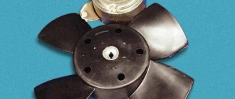
| №3 | Right cooling fan relay |
| №4 | Left cooling fan relay |
| №5 | Fuel pump relay (fuel) |
| №6 | Fuel pump fuse F5, 15A |
On some vehicle versions, a starter relay may be located under the additional unit next to the ignition relay.
Decoding error codes for VAZ 2110
Next, we consider the decoding of VAZ 2110 error codes that occur most frequently. For ease of reading, the information is divided into logical blocks.
Sensor failures
- 0030 – the control controller for the temperature of the air entering the intake manifold is damaged;
- 0032 – a short circuit occurred in the lambda probe lines touching the on-board circuit;
- 0036 – open circuit of the heater sensor installed after the catalyst;
- 0102 – Mass air flow sensor does not respond or is damaged, can also be caused by a malfunction of the flow meter, replacing the air filter may help;
- 0103 – erroneous signal from the mass air flow sensor, the faulty module may need to be replaced;
- 0112-113 – air temperature controller on the intake manifold – a defect has been detected;
- 0116 – DTOZh signal is interrupted or does not arrive evenly, the wiring may be damaged;
- 0117/118 – similar sensor, erroneous/too high signal;
- 0122/123 – TPS has failed or is acting up, the entire circuit will need to be fully diagnosed;
- 0130-132 – problems in the oxygen controller circuits;
- 0133 – slow response from control center 1;
- 0134 – the voltage in the lambda probe circuit has critically decreased;
- 0135 – the oxygen controller heater is damaged;
- 0140 - a similar error on the VAZ 2110 computer indicates a break in the DK2 control circuit;
- 0222 – TPS, open circuit or short circuit;
- 0325 – DD is damaged or the power line is ruptured;
- 0326/0327/0328 – the signal from the knock sensor has exceeded the maximum limit or is too low/line broken;
- 0336-337 – DPKV is broken or the wires are shorted;
- 0340/341 – DPRV is out of order or there is damage to the cables;
- 0342/343/346 – phase distribution sensor failed/control break/short circuit;
- 0500/0501 – the speedometer sensor is broken or shows incorrect data;
- 0504 – the actual position of the brake pedal does not correspond to the calculated indicator;
- 0505/0511 – DXH has failed, the engine speed may fluctuate, you also need to check the lines;
- 0830 – data from the clutch pedal position sensor is incorrectly read;
- 1135 – DK1 is damaged, line diagnostics are required;
- 1141 – the heater of the lambda probe installed in front of the catalyst is faulty;
- 1513/1514 – the XX sensor is damaged or the wires are shorted;
- 1617 – the rough road controller produces a value exceeding the nominal thresholds; it does not affect the operation of the internal combustion engine;
- 2020 – the position dampers of the intake elements do not work correctly;
- 2122/2127 – the gas pedal position sensor gives incorrect signals, the calculated position differs from the actual one;
- 2138 - the same, with a violation of pairing with each other.
VAZ 2110 error numbers for the power plant
- 0101 – Mass air flow sensor gives a false signal, the intake manifold may need to be cleaned;
- 0121 – there is no power supply to injector No. 3, usually the motor is rough;
- 0171 - VAZ 2110 engine error indicates that fuel supply is difficult, probably problems with the pump or filters;
- 0172 – the opposite problem, you should check the air leaks at the fuel line connections;
- 0204 – no voltage at engine injector 4;
- 0300 – multiple misfires detected;
- 0301-304 – similarly for each cylinder in order;
- 0335 – crankshaft desynchronization;
- 0363 – there is a misfire in one of the cylinders, the system has turned off the supply of the combustible mixture;
- 0422 – catalyst clogged;
- 0441/443/444 – the canister purge valve is damaged or there is no power to the element;
- 0485 – the main radiator fan is not working properly;
- 0506/507 – idle speed too low/high;
- 1140 – the actual load on the engine differs from the measured values;
- 1301/2 – gaps in the ignition system of the catalyst protection device;
- 1303/4 – misfire in 3/4 cylinders;
- 1335 – the throttle valve actuator is not working correctly;
- 1426 – canister purge valve, wiring damaged;
- 1545/1578 – throttle valve clogged or broken;
- 1602 - error 1602 VAZ 2110 indicates that a critical voltage drop has been detected in the on-board network;
- 2135 – the throttle device is acting up;
- 2187 - VAZ 2110 injector error says that too lean mixture gets into the working cylinders;
- 2188 – the opposite value of the above error;
- 2304 – too much voltage is supplied to one of the ignition coils.
Failures of electronic components and assemblies
- 0351/0352 – open circuit control of ignition coils No. 1 and 2, respectively;
- 0480 – the main fan relay circuit is de-energized;
- 0560 – there are voltage drops in the on-board network;
- 0562/563 – the voltage in the standard circuits has dropped/jumped significantly;
- 0601 – read-only memory module error;
- 0603 – similar for RAM;
- 0615 – the starter relay is damaged or the wiring is broken;
- 0628 – Short circuit of the fuel pump relay;
- 0650 – VAZ 2110 check errors, power failure of the corresponding lamp;
- 1336 – the wrong controller is installed, the pins of the standard connector may be damaged;
- 1425 – canister purge valve, short circuit to the body;
- 1541 – fuel pump control relay module – wiring damaged;
- 1570 – the immobilizer circuit is damaged;
- 1600 – the above element is damaged or deactivated;
- 1603 – the internal part of the microprocessor memory is damaged;
- 1612 – error reset – procedure failure;
- 1620 – internal memory module – there is a defect;
- 1621 – similar for RAM;
- 6060 – the ECU processor is not working properly;
- 2AAA – body control module has failed;
- U3FFF - The ECU is broken or de-energized.
Relay block diagram above the gas pedal
| №1 | Rear fog lamp relay |
| №2 | Rear window heating relay |
| №3 | Low beam relay |
| №4 | High beam relay |
Mounting blocks for Lada 4×4 2021
The main and additional units are located in the cabin to the left of the steering wheel, under the instrument panel. The blocks contain fuses of the “Cylinder” size, ten and six fuses, respectively. The ratings and purpose of the fuses are indicated in Table 4 “Circuits protected by fuses”:
Fuse block of standard size “Standard”. The block is located on the left side under the upholstery and contains fuses that are designed to protect engine control system devices. The ratings and purpose of the fuses are shown in Table 5:
The fuse and relay box is located on the left side of the steering column under the instrument panel. The block contains two “Standard” size fuses, which are designed to protect the circuits of the electric fuel pump, electric windows and electric mirrors. The ratings and purpose of the fuses are shown in Table 6:
The fuse and relay box is located on the right side of the steering column under the instrument panel. The block contains one “Maxi” size fuse and two “Standard” size fuses, which are designed to protect the circuits of the hydraulic unit of the anti-lock braking system. The ratings and purpose of the fuses are shown in Table 7:
Cause of error 14 on VAZ 2114
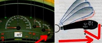
In addition to built-in on-board computers, models 2114 and 2115 with an injector have an error detection function through the dashboard. By holding down the odometer button and turning the ignition to the first position, the self-diagnosis process begins. The functionality of the fuel gauge, tachometer, speedometer and coolant temperature needles will be checked.
Common error 14 on the VAZ 2114 means a high signal from the antifreeze temperature sensor (the so-called DTOZH).
The reason for the appearance of code “14” lies in the following points:
- The temperature sensor is faulty;
- There is a break in the DTOZh connection circuit;
- The error codes were summed up and displayed on the panel as the sum “14” (options for other faults should be selected);
- The insulation of the sensor is broken, as a result of which it no longer transmits correct readings.
Useful : Where is the DTOZH located on the VAZ 2114?
As soon as error code 14 appears on the instrument panel of the VAZ 2114, you should replace it or check the reliability of the wiring connection to the DTOZH. In the VAZ 2114 model (injector, 8 valves), this element plays a rather important role in the formation of the correct air-fuel mixture and is responsible for the timely activation of the cooling fan.
Mounting blocks for Lada 4×4 2021
The turn signal relay (part number 8450082700, 9-pin), as well as the windshield wiper relay, are located under the trim in the driver’s feet, to the left of the fuse mounting block.
Attention!
The relay and fuse diagram may differ depending on the configuration and production date of the vehicle. Current diagrams of the mounting block are presented in the operating manual for the date of manufacture of the car (download from the official website for 3-door or 5-door).
Why does a fuse or light relay or any other constantly blow out? Before replacing it with a similar one, you must first find and eliminate the cause of its burnout. This could be a short circuit, incorrectly selected rated current, etc. Use electrical circuit diagrams to troubleshoot problems. Questions on this topic can be asked on the forum.
Other reasons
Reasons not directly related to the condition of the engine control and regulation systems may include problems with air supply systems, exhaust gas outlet systems, and fuel quality.
The condition of the intake system is affected by the conditions in which the vehicle is operated. When driving in dusty areas, the air filters should be replaced more often than the manufacturer recommends.
When the filter is “clogged,” the combustible mixture in the engine combustion chambers becomes depleted. Incomplete combustion of fuel occurs, or, as they say, the engine overflows. Soot forms on the spark plugs and the traction characteristics of the engine deteriorate.
If during operation the fastening of the intake system elements becomes loose, air leaks occur, exhaust gas recirculation systems do not work properly, the fuel mixture becomes lean due to excess air, and the engine does not develop full power. In this situation, it is necessary to check the condition of the fastening of the intake manifold and carburetor.
Exhaust system
Attention! If the car has a catalyst, then start checking the exhaust system with it. Check the condition of the lambda probe, the condition of the catalyst, whether it is “clogged” (due to poor quality fuel, carbon deposits may form on it). If the catalyst is faulty, exhaust gases will not completely exit the cylinders, which will lead to poor filling of the combustion chambers with the air-fuel mixture and a decrease in engine power.
If the seal of the exhaust manifold to the cylinder block is broken, exhaust gases will leak into the engine compartment, which can lead to engine overheating and incorrect operation of electronic systems. This problem can be corrected by tightening the manifold or replacing the gaskets under the intake manifold.
The engine spark plugs will tell you about bad fuel: if there is a red coating on the spark plug contacts and the “skirt” of the central electrode, then the fuel is good. Black carbon deposits on the spark plug indicate low quality fuel with a high content of impurities. The presence of soot impairs the quality of the spark plug.
Sometimes drivers say: the engine pulls poorly, the car does not reach maximum speed. Where to look for reasons? There may be several of them: - severe overheating of the engine; - faulty ignition system: the ignition setting is broken (ignition is too early or late); the centrifugal ignition timing regulator has become stuck; there is a malfunction in the vacuum ignition timing regulator; - insufficient filling of the cylinders with the working mixture; - interruptions in engine operation; - loss of compression in the cylinders; - entry of a lean working mixture into the cylinders.
If the engine does not develop full power, then it is best to check the serviceability of the ignition system. Note that if the ignition is too late, the engine loses throttle response and overheats. A significant reduction in power occurs due to the fact that the mixture does not have time to burn at the moment when the piston is in. m.t.
The combustion of the mixture continues as the piston moves downward; this is easy to determine by touching the exhaust manifold with your hand. It will be too hot because some of the mixture will burn when released. Too early ignition also has a harmful effect on engine operation, when the combustible mixture ignites prematurely and the force of the gases acts towards the piston, which moves towards the engine. m.t.
At the same time, frequent and loud metallic knocks are heard in the engine, the engine is prone to fuel detonation, does not work well at low speeds, and sometimes backfires when starting with the crank. Having established that power is lost due to ignition being too early or late, adjust it.
If it is not possible to achieve the desired results by adjusting the ignition timing, it means that there is a malfunction in the automatic ignition timing adjustment devices; centrifugal or vacuum regulators. It must be remembered that the centrifugal regulator regulates ignition timing only depending on the engine speed.
It usually starts working at 400-600 engine rpm. If malfunctions occur in the centrifugal regulator (weakening of the springs or sticking of weights), this will lead to disruption of the ignition timing. If the regulator weights jam, the ignition timing will remain the same at both low and high speeds.
Meanwhile, for high speeds, the ignition timing should be earlier. Late ignition at high speeds will cause a decrease in power and increase fuel consumption. If the regulator springs are weakened and the weights disperse completely, then even at low speeds there will be a large ignition advance, which will also lead to excessive fuel consumption and a decrease in power.
Usually the serviceability of the centrifugal regulator is checked using a synchronograph. But, as a rule, there are no instruments on the way. However, the operation of the centrifugal regulator can still be checked. How it's done? Without removing the distributor from the engine, you need to move the breaker lever and turn the cam by hand in the direction of rotation of the shaft until it stops.
The weights are moving apart. Release the cam and it will return to its original position under the force of the weight springs. If jamming is detected, it must be eliminated and the weakened springs replaced with new ones. From the above it is clear that the centrifugal regulator regulates the ignition timing only depending on the speed.
But on the way, the car has to move along different roads - flat and with inclines. Let us assume that when driving at a constant speed both on a flat road and on an uphill road, the centrifugal regulator will only provide the same ignition timing. While the engine load and throttle opening are significantly greater when driving on an uphill road, the ignition timing should be less than on a flat road when driving at the same speed.
The ignition timing is adjusted when the throttle opening (engine load) changes by a vacuum regulator. It may have the following malfunctions: - loss of spring elasticity; - air leakage into the spring plane; - jamming of the ball bearing of the breaker panel. When the vacuum regulator spring is weakened, at low and medium loads the ignition timing increases.
If air is sucked into the cavity where the spring is located (if the diaphragm is damaged), then the ignition timing will decrease at low loads. If there is too much air leakage, the vacuum regulator does not work at all. The vacuum regulator may also fail due to a stuck ball bearing on the breaker panel.
Like a centrifugal regulator, a vacuum regulator is usually checked for serviceability using a synchronograph. On the way, you can check it in the simplest way: rock the breaker panel on the bearing and make sure there is no excessive clearance, and also determine whether there is an increase in the gap between the panel finger and the diaphragm rod, and whether the rod itself is jumping off.
If you create a vacuum in the vacuum regulator tube disconnected from the carburetor, then if it is in good condition, the breaker panel should turn in the opposite direction of rotation of the cam. Having discovered that both advance angle regulators are working properly and the ignition is set correctly, the reason for the decrease in power must be sought in insufficient filling of the cylinders with the working mixture.
Also interesting: Niva tuning: 145 photos of ideas on how to improve the VAZ 2121 with your own hands
This may be caused by the throttle valve sticking on the axle (not opening it completely). You should check the throttle valve drive and, if necessary, remove jamming and clean the axle. Then make sure the air filter is working properly. If it is dirty, disassemble it, wash it and, if necessary, change the oil.
It is advisable to check the serviceability of the valves and springs of the gas distribution mechanism; in case of violation of the gaps or breakage (loss of elasticity) of the valve springs, weak and broken springs should be replaced, the gap should be adjusted. Insufficient filling of the cylinders with the working mixture can occur when the needle valve of the float chamber is stuck, a faulty muffler, the use of the wrong grade of fuel, as well as in the case of a large deposits of tar and coke in the intake pipe.
A common cause of incomplete engine power is the entry of a lean mixture into the cylinders. Reasons for the formation of a lean mixture: - the jets and channels in the carburetor are clogged, contamination (water freezing) of the fuel lines in the power system has occurred. Rinse and blow out the jets and channels, blow out dirty fuel pipes, and if necessary, clean them with wire; - stuck fuel pump valves or clogged sump mesh, a small rupture of the diaphragm.
First, eliminate the jamming of the fuel pump valves, wash the filter element and mesh, and replace the torn diaphragm with a new one or restore the functionality of the old diaphragm in the manner described earlier; - air leaks at the junction of carburetor parts, the carburetor flange with the intake pipe, the intake pipe flanges with the cylinder block due to loosening of fastenings, as well as damage to gaskets.
You can find the location of the leak using a match or soap foam. The flame of a match, brought to the intended place of suction, is deflected towards the gap, and a window is formed in the soap foam. Air leaks are eliminated by tightening the nuts or bolts, as well as replacing the corresponding sealing gaskets; - wear of the fuel pump drive lever, clogging of the air holes of the fuel tank filler plug, jamming of the air damper.
These defects are eliminated as follows: faulty parts of the fuel pump are replaced with new ones, the air holes of the plug are cleaned, the length of the choke control cable is checked and, if necessary, adjusted. Relatively often, the reason for a decrease in engine power is a drop in compression in the cylinders.