If the starter of your car turns normally, but the car does not start, the first thing you need to do is check that the fuel pump is turned on. On domestic cars, its operation can be heard from the passenger compartment; when the ignition is turned on, a characteristic buzzing sound comes from under the rear seat or trunk. If the fuel pump does not work, you need to check the integrity of the fuses and the activation of the main relay of the engine management system and the fuel pump relay. On the VAZ-2107, VAZ-2108, VAZ-2109 and their modifications, relays and fuses are located on the shelf under the glove compartment or under it. On VAZ-2110 and similar ones, you should look in the heater console on the passenger side by unscrewing the fastening screws and removing the side cover. On GAZ cars they are located under the hood on the front wall of the cabin, closer to the passenger side.
The fuel pump relay does not turn on.
If the fuel pump does not work, then first of all you need to check the attraction of the main relay and the fuel pump relay. If the main relay does not click, then it is necessary to check its switching circuit and its serviceability. How to do this is described in the article the main relay does not turn on,
In the case when the main relay turns on, but the fuel pump relay does not, it is necessary to check the power at pins 85 and 86. When using a test lamp, its current consumption should not exceed 0.25A, otherwise damage to the controller may occur. If the control lamp does not light up on any terminal, then the relay is not receiving power. This may be caused by a blown fuse or a broken power cord.
In the case when the lamp burns brightly on one terminal, and at half-glow on the second, and the relay may be activated, you should remove the relay from the socket and connect terminals 85 and 86 with a test lamp. When the ignition is turned on, the control lamp should light up and go out after approximately 20 - 30 seconds. If the lamp lights up and there is poor contact in the connection between the block and the fuel pump relay. If the lamp does not light up, there may be a break in the wire connecting the relay to the controller or the controller itself may be faulty.
Popular breakdowns
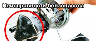
Problems with the fuel pump can occur for several reasons. Therefore, your first priority is to determine the source of the problem. These may be:
- Fuel pump fuse;
- Fuel pump relay;
- Pump weight;
- Motor;
- Contacts;
- The pump itself.
If one of these elements fails, it can stop the normal functionality of the entire module.
Let us consider the situations with each of the specified elements of the fuel module in more detail.
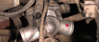
Pressure
What exactly is a fuel pump? This is an element of the fuel system that allows fuel to pass through due to pressure. Therefore, if you take pressure measurements, you can get answers to many questions.
Let's give an example of normal pressure readings when checking in certain modes.
Check mode
Normal indicator
At idle
Without pressure regulator tube
When the drain is pinched
When you press the gas pedal
We recommend measuring with a small range of atmospheres on a pressure gauge (up to 7 atm). This will reduce errors to a minimum. Having a pressure gauge at hand will allow you to significantly save on professional diagnostics.
Contacts
The fuel pump includes three wiring:
- Plus (positive);
- Minus (negative);
- Fuel level indicator.
So, failure of the pump may occur due to a simple violation of the integrity of the wires. So if the pressure check shows normal, then we definitely examine the condition of the wiring.
To check, you will need a 12V lamp, which is attached to the external connectors of the pump with positive and negative contacts. Turn the ignition key. If the lamp blinks, contact is present. In this case, you will have to check the condition of the internal contacts.
Motor
If the pressure and wiring are normal, let's try to check the serviceability of the motor. It is this element that is responsible for moving fuel through the system.
- To check it, you will need the same 12V lamp;
- Attach it to any motor terminal;
- Turn the ignition key;
- If the lamp blinks, you will have to get rid of the motor and buy a new one.
Motor
Don't jump to conclusions. Before checking, look at the condition of the terminals and motor wiring.
Fuel pump weight
The contacts are fine, but the fuel level sensor may provide incorrect information. In this case, you definitely need to check the weight of the pump responsible for dispersing the fuel.
It often turns out that after prolonged use or driving on difficult road sections, the mass simply loses its fastening strength. Accordingly, if the mass falls off, the pump will not be able to work.
The mass is attached to the pump under the dashboard in the area of the hand brake. Therefore, when the driver turns on the handbrake, there is a possibility of hitting the ground contact, which is why it will fall off.
Putting the mass back in place is not that difficult. The problem is caused by the path to it. You'll have to:
Weight
The fuel pump relay is located exactly where the ground is. Therefore, there should be no problems with the search.
With an ideally working fuel supply system, when the ignition is turned on, the relay instantly creates pressure inside the system, and then turns off.
If this process is disrupted, you will have to:
- Lift the front facing panel, which covers the contacts of the audio system and air conditioning;
- Take a look from the front passenger side;
- Find three relays;
- The lowest one is our desired pump relay;
- Turn the ignition key;
- If you hear a characteristic click from the relay, it is working properly;
- If there is no click, check the contacts. The reason is either them or a failed relay.
https://youtube.com/watch?v=ybkjMCy6iGw
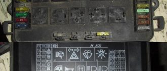
Fuse
All that remains is to check the condition of the fuse. This stage will make sure who the real culprit of the problems is - the pump itself or its fuse.
Fuse location
- Getting to the fuse is as easy as getting to the relay - through the hood or from the inside. The first option is preferable.
- Raise the hood and look in the area near the windshield.
- There is a dark-colored box located directly on the electronic engine control unit.
- Open the box and look inside for the topmost fuse.
- It has a current strength of 15A, as well as an inscription in English - Fuel Pump, that is, a fuel pump.
- Examine its external condition by removing it from the box.
- If the contacts are intact, then everything with the fuse is normal.
- If burnt contacts are clearly visible, consider purchasing a new device. Its price is affordable, so finding and replacing should not be a problem.
The fuel pump does not work, the relay turns on.
Checking relay power.
In the case when the fuel pump relay turns on when the ignition is turned on, but the pump itself does not work, you need to check the power at terminal 87 of the fuel pump relay. To do this, touch terminal 87 of the relay socket with the output of the control lamp connected to the vehicle ground, and the lamp should light up. If the lamp does not light, it means the fuse has blown or there is a break in the wire.
If there is power at terminal 87, you should remove the relay from the socket, and instead place a jumper between pins 87 and 30. In this case, if the pump and connecting wires are working properly, the pump should start working and if this happens, the relay should be changed. If the pump does not start working, then, without removing the jumper, you need to touch the power wire on the fuel pump with a test lamp connected to the vehicle ground.
Checking the fuel pump power circuit.
If a submersible pump is installed on the car as part of the fuel module, you need to remove the connecting connector and touch one of the thick wires. When you touch one of them, the indicator lamp should light up. If the lamp does not light up on any of the wires, then it is necessary to eliminate the break in the wire from the fuel pump relay to the module connector or the pump itself, if the pump is of a remote type. One of the reasons for the break may be the anti-theft blocking of an installed non-standard alarm system.
In the case when the test lamp lights up on one of the thick wires of the connector or one of the terminals of the remote pump, you need to connect these terminals with a test lamp to each other. In this case, the control lamp should light up. If the lamp does not light, it is necessary to eliminate a break or poor contact in the wire connecting the pump to the vehicle ground.
If, when checking the wires and relay for turning on the fuel pump, no malfunction is detected, the electric motor of the fuel pump or its connection to the module connector is faulty. It is not difficult to find the cause by removing the fuel pump module from the tank. If there is poor contact with the connector, melting of the plugs will be visible. If melting is not noticed, then to check the pump itself, you can connect it to the battery. It should be taken into account that operating a submersible pump without liquid will damage the pump. A faulty pump should be replaced.
Schematic electrical diagrams, connecting devices and pinouts of connectors
The fuel pump on a car is designed to supply fuel to the combustion chamber. Its operation is controlled using a relay. On a VAZ (depending on the model), the fuel supply unit can be electrical or mechanical - it all depends on the fuel supply system. On a fuel-injected car, the fuel pump is located in the tank. When the ignition is turned on, voltage is supplied to the terminals of the unit and it begins to pump fuel. If the required pressure is created in the system, the relay automatically turns off the fuel pump - the engine is ready to start.
When the ignition is turned on, the relay creates pressure in the fuel lines by turning on the fuel pump (BN) for a couple of seconds. After this, the BN will work either when the engine is cranked by the starter, or when the engine is running.
Sometimes this system needs repairs - there is nothing complicated here, and the editors of the 2Skhema.ru website will tell you how to do it yourself. Let's start with the BN pinout, then we will indicate it on the diagrams and at the end there will be instructions for replacing the fuel supply elements.
Operating principle and symptoms of malfunction
The fuel pump is a small electric motor that pumps fuel and creates operating pressure in the fuel rail. It is a component of the fuel module. The fuel module of the VAZ 2114 car is a single unit, which, in addition to the pump, includes:
- fuel sensor that controls the fuel level, assembled with a float;
- intake chamber;
- filter element.
The pump is driven by an electric motor powered from the on-board network. Structurally, the pump and the electric motor that drives it are one unit. The electrical component of the assembly is washed with gasoline. This is required in order to provide cooling to the electric drive of the pump, since it heats up quite quickly during operation.
Pinout of fuel pump VAZ 2107
1 – radiator fan drive motor; 2 – mounting block block; 3 — idle speed sensor; 4 – engine ECU; 5 – potentiometer; 6 – set of spark plugs; 7 – ignition control unit; 8 – electronic crankshaft position sensor; 9 – electric fuel pump; 10 – indicator of the number of revolutions; 11 – lamp for monitoring the health of electronic systems and the brake system; 12 – ignition system control relay; 13 – speedometer sensor; 14 – special factory connector for reading errors using the BC; 15 – injector harness; 16 – adsorber solenoid valve; 17, 18, 19,20 – fuse box for repairing the mounting block that protects the injection system circuits; 21 – electronic fuel pump control relay; 22 – electronic relay for controlling the exhaust manifold heating system; 23 – exhaust manifold heating system; 24 – fuse protecting the heater circuit; 25 – electronic air sensor; 26 – coolant temperature control sensor; 27 – electronic air damper sensor; 28 – air temperature sensor; 29 – pressure control sensor and low oil pressure lamp.
You can check the fuel pump on a VAZ 2107 simply by checking the voltage at its connection block with a tester. The presence of voltage will indicate a malfunction of the electric motor. Instead of a tester (multimeter), you can use a test lamp to diagnose a malfunction.
In the absence of one, this can be done by disconnecting the connection block for the fuel pump and fuel level control and applying voltage with wires from the battery to the place where the gray wire is connected +12 and to the place where the black wire is connected - minus. A humming pump will indicate a faulty fuse, power circuit or ECU.
Diagnostics
A malfunction of the VAZ 2114/2115 fuel pump can be caused by:
- malfunctions in the device’s power supply circuit;
- failure of starting and protection elements (relay and fuse);
- wear of electric motor parts.
Checking the electrical circuit
At the beginning of the diagnosis, you should check the electrical circuit of the fuel pump. To do this you will need:
- car tester (multimeter);
- crosshead screwdriver;
- two pieces of wire about 2 m long.
Checking the electrical circuit is carried out in the following order:
- Turn on the ignition without starting the engine. When the key is in the first position, a click should be heard, characteristic of turning on the relay, followed by a slight whirring of the pump electric motor. If there is no click, the relay is faulty or is not receiving power. If there is a click, but no buzzing, the wiring coming from the relay or the pump motor itself is faulty.
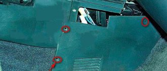
- Under the glove compartment, find an additional mounting block consisting of three relays and three fuses. The pump relay is located in the middle, and the fuse is located to the left of it. Remove the fuse from its socket, test it with a multimeter, and if the result is negative, replace it. When replacing the fuse, please note that it is rated for a maximum of 15 A.
The relay and fuse for the fuel pump on the VAZ 2114/2115 are located in the mounting block under the glove compartment.
Set your multimeter to voltmeter mode. Connect one probe of the device to the relay terminal to which the pink wire fits, and the second to the car body. Turn on the ignition. The device should show the on-board network voltage in the range of 11.7–12.4 V. If there is no voltage, the problem may be a broken wiring or a malfunction of the ignition contact group. In this case, it is better to contact an auto electrician. If power is supplied, check that the relay is working. With the ignition on, use a screwdriver or a piece of wire to close the contacts to which the pink and gray wires go. This closes the circuit bypassing the relay. If the fuel pump works, replace the relay.
The ground wires of the fuel pump are attached to the body with a self-tapping screw
Pressure check
If the pump is working properly, but the engine begins to operate intermittently, you should check the fuel pressure in the system. For this you will need:
- pressure gauge (can be a tire gauge with a measurement limit of 5–7 kPa);
- petrol-resistant hose with a diameter of 10–12 mm and a length of 50–80 cm;
- two clamps for a hose of the appropriate diameter;
- Phillips screwdriver;
- nipple cap;
- dry rag.
In addition, the presence of an assistant is desirable.
The verification procedure is as follows:
- In the engine compartment on the engine fuel rail, locate the pressure measuring fitting (on the right side).
- Remove the plastic cap (plug) from the fitting.
Find the pressure fitting and remove the cap from it
When unscrewing the spool valve, fuel may spray out of the fitting.
Connect the pressure gauge to the fitting using a hose and clamps
Pinout BN VAZ 2108, 2109, 21099
The fuel pump activation relay (2) is shown by an arrow.
1 — nozzles; 2 — spark plugs; 3 — ignition module; 4 — diagnostic block; 5 - controller; 6 — block connected to the instrument panel harness; 7 - main relay; 8 - main relay fuse; 9 — electric fan relay; 10 — controller power supply fuse; 11- electric fuel pump relay; 12 — fuel pump power circuit fuse; 13 — mass air flow sensor; 14 — throttle position sensor; 15 — coolant temperature sensor; 16 — idle speed regulator; 17 — knock sensor; 18 — crankshaft position sensor; 19- oxygen sensor; 20- APS control unit; 21 — APS status indicator; 22 — speed sensor; 23 — electric fuel pump with fuel level sensor; 24 — solenoid valve for purge of the adsorber; 25 — block connected to the ignition system harness; 26 — instrument cluster; 27 — ignition relay; 28 — ignition switch; 29 — mounting block; 30 — electric fan of the cooling system;
A - to terminal “B+” of the generator; B - block connected to block K of the ignition system harness; C - block connected to block L of the ignition system harness; D - wire connected to the interior lamp switch; E - wire connected to the white and black wires disconnected from the interior lamp switch; F - to the “+” terminal of the battery; G1, G2 - grounding points; K - block connected to block B of the front harness; L — block connected to block C of the front harness.
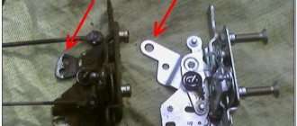
On “nines” with a mechanical fuel pump, the most common malfunction is wear of the fuel pump diaphragm, as a result of which gasoline will leak through the drainage hole in the housing when it operates. The second reason for the failure of such a fuel pump is wear of the pusher, which transmits force from the camshaft cam to the fuel pump drive lever.
Mechanical fuel pump repair
The functionality of a mechanical fuel pump can be restored by replacing its faulty elements. You can buy them at any automobile store. But it is better to buy not individual spare parts, but a repair kit. It includes all the elements that can fail:
- intake and exhaust valves;
- diaphragms with spacers, “plates”, rod;
- pusher;
- thermal spacer;
- gaskets
Replacing valves
To replace the pump valves you will need a slotted impact driver and a small hammer. The valves are held in their seats by punching at three points. These areas must be carefully knocked off with a screwdriver. After this, the valves can be removed. Having installed the new parts, we secure them with cores. To do this, place the tip of the screwdriver on the edge of the housing along the circumference of the socket and strike it lightly with a hammer. We fix each valve in three places.
Replacing valves
How to change apertures
To replace the diaphragms, you need to unscrew the nut by 10 in the upper part of the rod. Next, we remove the damaged elements, and in their place we install parts from the repair kit.
The kit includes three diaphragms: two working and one safety. The latter serves to prevent unauthorized fuel from entering the carburetor if the first two are damaged. It is installed at the very bottom of the rod immediately after the lower “plate”. We place spacers on top of it on the rod: first a small one, then a large one. We place the working membranes and the upper “plate” on them. We secure the resulting structure with a nut.
The mechanical fuel pump has 3 diaphragms
Replacing the pusher, thermal spacer and gaskets
The thermal spacer does not need to be replaced unless it is damaged. Inspect its mating surfaces, especially the outer one, to which the lower part of the pump housing is attached. It should be perfectly smooth. Otherwise, oil leakage may occur at the junction of parts during engine operation.
Replacing the pusher is carried out by removing the old one and installing a new rod in its place. There is no difference in which end where it will be installed.
Now about the gaskets. There are only three of them in the repair kit, and they have different thicknesses:
- “A” – 02.27–03 mm;
- “B” – 0.7–0.8 mm;
- “C” – 1.1–1.3 mm.
The first is intended for installation between the thermal spacer and the auxiliary drive housing, and the gaskets “B” and “C” are used to adjust the protrusion of the pusher above its mating surface.
The adjustment is made as follows:
- We install the thermal spacer with the first gasket and a new rod into the auxiliary drive housing.
Installation of gaskets and thermal spacer - Place gasket “B” on the mating plane of the spacer.
Next, you need to rotate the engine crankshaft to the position of the pusher until it is recessed as much as possible. This can be done using a large slotted screwdriver. We insert its end into the clutch housing window and slowly push the flywheel clockwise. The thinnest gasket is installed between the spacer and the accessory drive housing - We periodically check the position of the pusher and measure its protrusion.
When it enters the auxiliary drive housing to its maximum length, we measure how much it protrudes above the mating plane of the spacer with the gasket already installed on it. This value should be 0.8–1.3 mm. If it is larger, replace gasket “B” with gasket “C”. If the protrusion length is less than specified, swap gaskets “A” and “B”. The pusher should protrude 0.8–1.3 mm above the mating plane of the spacer
After the adjustment is completed, the fuel pump is installed in place and secured with nuts.
VAZ 2110 fuel pump pinout
If the fuel pump works directly when connected to the battery, then you will have to ring the wires going from it to the fuel pump relay, and if it does not work, then either replace it with a new one, or you will have to disassemble it and look for a fault inside the fuel pump.
Motor
Fuel pump motor VAZ 2114
We checked the pressure and wiring, everything works like clockwork, but the engine stalls. The fuel pump may not pump due to a breakdown of the motor - the main element that drives fuel. We check its functionality with the same light bulb: attach its wires to any terminal of the motor, turn the ignition. The lamp blinked - it was time to throw out the motor. And again, run to the store for a brand new motor.
The terminals may oxidize and not make contact, as a result of which the fuel pump will not pump. The motor in this case may be normal. And the terminals just need cleaning (possibly re-soldering). There is an opinion that the terminals are oxidized due to low-quality fuel (the octane number does not match the declared one).
Pinout BN VAZ 2113, 2114, 2115
— block headlights; — gearmotors for headlight cleaners*; - fog lights*; — ambient temperature sensor; - sound signals; — engine compartment lamp switch; — electric motor of the engine cooling system fan; — generator; — low oil level indicator sensor; — washer fluid level sensor; — front brake pad wear sensor; — wire tips connected to the common windshield washer pump**; — windshield washer pump; — headlight washer pump*; — wire ends for connecting to the rear window washer pump on VAZ-2113 and VAZ-2114 cars; — low oil pressure indicator sensor; — engine compartment lighting lamp; — wire lug for connecting to the wiring harness of the engine control system; — gear motor for windshield wiper; — starter; — a block connected to the wiring harness of the ignition system on carburetor cars; — coolant temperature indicator sensor; — reversing light switch; — low brake fluid level indicator sensor; - accumulator battery; — low coolant level indicator sensor; — relay for turning on fog lights; - mounting block; — brake light switch; — plug socket for a portable lamp; — hydrocorrector scale illumination lamp; — switch for the parking brake indicator lamp; — block for connecting a backlight lamp; — switch for instrument lighting lamps; - Understeering's shifter; - hazard warning switch; — front seat heating element relay; — ignition switch; — rear fog light circuit fuse; - fuse for the front seat heating elements; — door lock circuit fuse; — front ashtray illumination lamp; — ignition relay; - cigarette lighter; — glove box lighting lamp; — switch for the glove compartment lighting lamp; — heater fan electric motor; — additional resistor for the heater electric motor; — heater fan switch; - heater switch illumination lamp; — lamp for illuminating the heater levers; — gear motors for electric windows of the front doors; — power window switch for the right front door (located in the right door); — gear motors for locking front door locks; — wires for connecting to the right front speaker; — gearmotors for locking rear doors; — wires for connecting to the right rear speaker; — door lock control unit; — wires for connection to radio equipment; — headlight cleaner switch*; — rear window heating element switch; — relay for turning on the rear fog lights; — block for connection to the heating element of the right front seat; — rear fog light switch; — switch for the heating element of the right front seat; — fog light switch*; — switch for external lighting lamps; — left front seat heating element switch; — block for connection to the heating element of the left front seat; — wires for connecting to the left front speaker; — power window switch for the left front door (located in the left door); — power window switch for the right front door (located in the left door); — wires for connecting to the left rear speaker; — side direction indicators; — courtesy light switches on the front door pillars; — courtesy light switches on the rear door pillars; - lampshade; — ceiling lamp for individual interior lighting; — block for connecting to the wiring harness of the electric fuel pump; — trunk light switch; — instrument cluster; — trunk lighting lamp; — display unit of the on-board control system; - trip computer*; — block for connecting the wiring harness of the engine control system; — rear exterior lights; — rear interior lights; — pads for connecting to the rear window heating element; — license plate lights; — additional brake signal located on the spoiler.
Replacing an electric fuel pump on a VAZ
- Reduce pressure in the fuel supply system.
- Using the fuel supply hose tip clamp, disconnect 2 hoses in turn.
- Unscrew the 8 nuts around the circumference of the clamping ring and remove it.
- A wire with negative polarity is attached to one of the nuts; it must be removed carefully.
- We take the electric pump block out of the fuel tank, tilting it slightly, to keep the fuel level indicator sensor lever intact, otherwise it will produce incorrect parameters.
- Remove the sealing rubber ring of the fuel block. If its properties are lost, the product must be replaced.
- Install the pump in reverse order.
When installing fuel hoses, focus on the direction of fuel supply indicated by the arrows, and the installation arrow on the electric pump cover should point towards the rear of the car!
Symptoms of a fuel pump malfunction and methods for diagnosing them on an injection engine
The power systems of modern fuel-injected internal combustion engines use an electric fuel pump. Depending on the installation location, there are submersible (installed in the tank) and flow-through fuel pumps (cut into the fuel supply line).
Main components of an electric fuel pump:
- two-piece body;
- DC motor;
- pumping section.
According to its design, the section can be rotary, blade, gear or turbine type. The latter option, due to its simplicity of design, has earned the greatest popularity. The rotation of the impeller attached to the electric motor shaft creates zones of high and low pressure, due to which fuel is taken and pumped from the tank into the pipelines.
Motor power circuit
In addition to the submersible fuel pump, the fuel module located in the tank includes:
- float type fuel level indicator sensor;
- critical gasoline level sensor;
- coarse filter;
- built-in fuel pressure regulator (RDT). This type of RTD is found on returnless power systems. Another type of design involves the presence of a fuel return line and a regulator mounted in the fuel rail;
- inlet and outlet fuel lines;
- electrical connectors.
Symptoms of a worn fuel pump motor:
- uncertain engine start;
- failures when sharply pressing the accelerator pedal;
- insufficient power at high speeds;
- The engine periodically stalls and refuses to start for some time. Often in such cases, several blows to the tank help bring the fuel pump back to life.
The cause of the described symptoms is worn brushes and the electric motor commutator. When the brushes are worn out, they do not press well against the lamellas of the commutator, which is why the current in the circuit drops, which leads to a decrease in the performance of the fuel pump.
Wear of electric motor components is the most common reason why the fuel pump does not pump gasoline well.
If power comes to the connector, but fuel does not flow from the pump, the reason may be melting of the plastic housing due to overheating or critical wear of the brushes/commutator. In this case, when you turn on the ignition, you will not hear a characteristic buzzing sound from the fuel module. Sometimes a situation in which the fuel pump pumps, but no gasoline comes out, occurs due to poor fixation of the corrugation going from the pump to the outlet fittings of the fuel section. Due to the pressure created by the pump, the corrugation jumps off the fitting.
If the gas pump works but does not pump enough gasoline, first of all pay attention to the coarse and fine filters. Clogged filters can be identified by the fact that the fuel pump hums louder than usual
Please note that operation under load reduces the service life of the transformer. The cause of insufficient pressure may also be a faulty fuel pressure regulator, which discharges too much fuel into the return line.
Failure of the fuel pump due to wear of the elements of the pump section occurs only in the case of low-quality components. You are more likely to replace the fuel pump due to worn brushes than to face mechanical wear on the pump section components.
Where is the fuel pump relay located?
Where is the fuel pump relay located? The installation location of the relay varies depending on the make of the car. Most often, it is located under the hood, in the fuse and relay box.
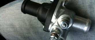
The fuel pump relay is designed in the circuit to prevent accidental application of high voltage to the fuel pump winding. The relay is standard and consists of a plastic body and coils with contacts. It is located in the car interior near the console. To access it, you need to remove the protection cover.
In appearance, it is a small box that resembles a “plug” with an American type of output. Each terminal has a marking that indicates the following: 31 – mass; 30– +12V constant (regardless of ignition); 15– +12 with the ignition on; 50– +12 when the starter is running; TD – signal from the ignition system; TF – engine temperature signal from the injection control unit KE. Outputs: 87 – supplies power to the fuel pump; 87H – oxygen sensor heating; 87V – turns on the starting injector.
But sometimes the fuel pump does not turn on when the key is turned in the ignition. With what it can be connected? First of all, the fuse, although if it had blown, it would not work at all. Maybe the contact is bad?
If the electric fuel pump does not show any signs of life when the ignition is turned on, this does not mean that it has burned out. The cause of the malfunction may also be a relay. The easiest way to test your hearing is that when you turn on the ignition, the relay should click. If you don’t hear a click, there is a high probability that the “relay” is faulty.
It’s easy to check the functionality of the pump itself, so we do this:
- remove the protective casing, under which there is a block with relays and fuses;
- we unscrew the fastenings of the block, remove it, it remains attached to the wires;
- we pull the RB out of the block, place a jumper between two opposite contacts, thus directly supplying power to the BN;
- if with such a connection the electric motor of the pump begins to make noise, it means that the BN itself is working, most likely the fault is hidden in the relay;
- if there is no voltage on any of the contacts on the RB block, you should look for a break in the wiring; there may also be poor contact at the place where the wire is attached to the terminal.
WHAT GASOLINE TO POUR IN THE VAZ-2114?
This topic has become overgrown with various conjectures and speculations, but we will try to put everything in its place.
The technical data sheet of the fourteenth indicates that the car engine requires AI-95 gasoline, and there is no reason not to trust the manufacturer’s recommendations.
Another thing is that many car owners, over their long driving experience, have accumulated rational doubts about the existence of any serious differences between 95 and 92 gasoline. Adding fuel to the fire was the recent statement by the chief engineer of the Moscow oil refinery, A. A. Abrosimov, that we do not make 95-grade gasoline in our country, and everything that is sold under its guise is either 92-grade or unknown fuel brought from somewhere.
As evidenced by reviews from VAZ 2114 owners who use exclusively 92-octane gasoline, there were no problems with the car during its service life due to fuel, and they see no point in using a more expensive analogue. However, the final decision about what to pour into the fourteenth is yours.
Video instructions for replacement
Click to enlarge (600 KB)
Description:
1 — headlight block VAZ 2114; 2 — gearmotors for headlight cleaners*; 3 — fog lights*; 4 — ambient air temperature sensor VAZ 2114; 5 — sound signals of VAZ 2114; 6 — engine compartment lamp switch; 7 — electric motor of the VAZ 2114 cooling system fan; 8 — VAZ 2114 generator; 9 — sensor for low oil level indicator VAZ 2114; 10 — washer fluid level sensor; 11 — front brake pad wear sensor; 12 — wire tips connected to the common windshield washer pump**; 13 — windshield washer pump VAZ 2114; 14 — headlight washer pump*; 15 — wire ends for connecting to the rear window washer pump on VAZ 2113 and VAZ 2114 cars; 16 — low oil pressure indicator sensor; 17 — lamp for lighting the engine compartment of the VAZ 2114; 18 — wire lug for connection to the wiring harness of the engine control system or to the wiring harness of the ignition system on carburetor VAZ 2114 vehicles; 19 — windshield wiper gearmotor; 20 — starter VAZ 2114; 22 — coolant temperature indicator sensor VAZ 2114; 23 — switch for reversing lights VAZ 2114; 24 — low brake fluid level indicator sensor; 25 - battery; 26 — sensor for insufficient coolant level indicator; 27 — relay for turning on fog lights VAZ 2114; 28 — mounting block VAZ 2114; 29 — brake light switch; 30 — plug socket for a portable lamp; 31 — lamp for illuminating the hydrocorrector scale of the VAZ 2114 headlights; 32 — parking brake warning lamp switch; 33 — backlight lamp connection block; 34 — switch for instrument lighting lamps; 35 — steering column switch; 36 — alarm switch; 37 — relay for the heating element of the front seats of the VAZ 2114; 38 — ignition switch VAZ 2114; 39 — rear fog light circuit fuse; 40 - fuse for the circuit of heating elements for the front seats of the VAZ 2114; 41 - door lock circuit fuse; 42 — front ashtray illumination lamp; 43 — ignition relay VAZ 2114; 44 — cigarette lighter; 45 — glove box lighting lamp; 46 — glove compartment lighting switch; 47 — electric motor of the VAZ 2114 heater fan; 48 — additional resistor of the heater electric motor; 49 — heater fan switch VAZ 2114; 50 — heater switch backlight; 51 — lamp for illuminating the heater levers of the VAZ 2114; 52 — gear motors for electric windows of the front doors; 53 — right front door power window switch (located in the right door); 54 — gearmotors for locking front door locks; 55 — wires for connecting to the right front speaker; 56 — gearmotors for locking the rear doors of the VAZ 2114; 57 — wires for connecting to the right rear speaker; 58 — control unit for blocking the door locks of the VAZ 2114; 59 — wires for connecting to radio equipment; 60 — switch for headlight cleaners VAZ 2114*; 61 — switch for the heated rear window element of the VAZ 2114; 62 — relay for turning on rear fog lights; 63 — block for connection to the heating element of the right front seat of the VAZ 2114; 64 — switch for the rear fog lights of the VAZ 2114: 65 — switch for the heating element of the right front seat of the VAZ 2114; 66 — fog light switch VAZ 2114*; 67 — switch for external lighting lamps; 68 — switch for the heating element of the left front seat of the VAZ 2114; 69 — block for connection to the heating element of the left front seat; 70 — wires for connecting to the left front speaker; 71 — left front door power window switch (located in the left door); 72 — left front door power window switch (located in the left door); 73 — wires for connecting to the left rear speaker; 74 — side direction indicators VAZ 2114: 75 — lamp switch on the front door pillars; 76 — lamp switch on the rear door pillars; 77 — lampshade; 78 — canopy for individual interior lighting; 79 — block for connecting to the wiring harness of the VAZ 2114 electric fuel pump; 80 — trunk light switch; 81 — instrument cluster of VAZ 2114: 82 — trunk lighting lamp; 83 — display unit of the on-board control system of the VAZ 2114; 84 — trip computer VAZ 2114*; 85 — block for connecting the wiring harness of the engine control system; 86 — rear external lights of VAZ 2114; 87 — rear internal lights of VAZ 2114; 88 — block for connection to the rear window heating element; 89 — license plate lights; 90 - additional brake signal located in the spoiler of the VAZ 2114.
Ignition system and starter connection diagram
The VAZ wiring diagram includes a VAZ ignition system module, consisting of two high-voltage transformers and two electronic control units. They are in a durable plastic case, from which 4 high voltage wires are removed. They have a connection that creates a synchronous passage of a spark entering the cylinders of the power plant.
The VAZ 2114 ignition module consists of a two-spark coil and is of the block type. The ignition switch turns on a relay that sends a signal to the controller. The latter is the control element of the injection system for starting the fuel pump. It is connected to the cleaning filter with a flexible hose. After this, gasoline is supplied to the fuel rail, from which the fuel is supplied to the injectors.
The pinout of the VAZ ignition switch is in itself. It has an anti-theft device. When the lock socket illumination is on and the engine is running, the anti-theft locking device blocks the VAZ starter from re-engaging.