Gazelle until 2009. Electrical circuits - part 1
Diagram of the engine control system UMZ-4216, ZMZ-40522: 1 – electronic unit of the engine control system; 2 – phase sensor (camshaft position sensor); 3 – crankshaft position sensor; 4 – throttle position sensor; 5 – knock sensor; 6 – mass air flow sensor; 7 – coolant temperature sensor; 8 – air temperature sensor in the intake pipe; 9 – oxygen concentration sensor (for engines with a catalytic converter); 10, 11, 12 and 13 – nozzles; 14 – idle speed regulator; 15 – canister purge valve (for a car with a fuel vapor recovery system); 16 – fuel pump relay; 17 – fuel pump electric motor; 18 – engine control system relay; 19 – diagnostic connector; 20 – block for connection to the tachometer; 21 – block for connecting the engine control system to the vehicle’s electrical network; 22 – relay for turning on the electromagnetic fan clutch; 23, 26 – ignition coils; 24, 25, 27 and 28 – spark plugs; a – connection diagram of injectors on a car with a UMZ-4216 engine (1, 2, 3 and 4 injectors)
Diagram of electrical equipment of cars with UMZ-4216, ZMZ-40522 engines: 1 — left side direction indicator; 2 — left headlight; 3 — right headlight; 4 — right side turn signal; 5 - starter; 6 — fuse box (in the engine compartment); 7 — headlight relay; 8 - central lighting switch; 9, 10 — lampshades for cargo compartment lighting (for vans); 11 — canopy lighting for the front part of the cabin; 12 — windshield washer motor; 13 — courtesy lamp for the rear part of the cabin (for vehicles with two rows of seats); 14 — switch for the interior lighting of the rear part of the cabin (for vehicles with two rows of seats); 15 — platform lamp (GAZ-3302, -33021, -33027); 16 — buzzer switch (GAZ-3302, -33021, -33027); 17 — driver signal buzzer (GAZ-3302, -33021, -33027); 18 — sound signals; 19 — sound signal relay; 20 — ignition switch; 21 — starter relay; 22 - generator; 23 - battery; 24 — battery switch; 25 — remote battery switch button; 26 — electric drive of the heater valve; 27 — electric pump for additional heater; 28 — heater electric fan resistor; 29 — heater fan electric motor; 30 — heating and ventilation control panel (1 — heater tap switch; 2 — backlight lamp for the heating and ventilation control panel; 3 — relay; 4 — main heater electric fan switch; 5 — electric fan and auxiliary heater electric pump switch); 31 — upper fuse box (in the cabin); 32 — lower fuse block (in the cabin); 33 — engine compartment lamp; 34 — hazard light switch;
What is an electric heater valve?
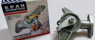
Electric heater valve (heater control valve with electric drive, heater valve) is a component of the vehicle interior/cabin heating system; a tap or valve to control the supply of coolant from the engine cooling system to the heater radiator (heat exchanger).
An electrically operated faucet is similar to a mechanical faucet, but is driven by a built-in electric motor or solenoid. This solution made it possible to abandon the cable drive and implement control of the heater using a button. Electric cranes make it possible to implement various schemes for heating the interior and operating the engine cooling system, while they are easy to use, reliable in operation and have a simple design.
Features of the electric crane
Each car powered by an internal combustion engine is equipped with an interior heating system, which is directly related to the operation of the engine cooling system. In order to control the furnace equipment, a special tap is used. It is the electric heater valve that is becoming more and more common, which has replaced morally and technically outdated mechanical models.
A similar transition from mechanics to an electric version was carried out by manufacturers of Gazelle commercial vehicles.
Before replacing the unit yourself, the driver should know how it works and what the operating principle of the system with an electric crane is based on.
The electric heater valve, widely used in automobile production, is distinguished by the presence of an electric drive in its design. This is a type of stove valve. It is part of the car heating system and serves to control the supply of cooling liquid from the internal combustion engine cooling system to the heater radiator.
In fact, this is an analogue of a mechanical unit, but here the drive is implemented through the use of a built-in electric motor or solenoid. The transition to electric cranes made it possible to abandon the use of cable drives, as well as switch to controlling the stove in the cabin using a button panel.
Types, design and operating principle of electric heater valve
Electrically controlled faucets existing today are divided into groups according to the type of shut-off element and its drive, and according to the number of circuits (and, accordingly, pipes).
Based on the number of circuits and pipes, heater valves are:
- Single-circuit / 2-pipe - ordinary taps / valves;
- Double-circuit / 3-pipe - three-way valves.
Double-port valves are valves that can only open and close the flow of liquid. In such a faucet, one pipe is inlet, the second is outlet, and between them there is a shut-off element. The dual-port heater valve is used in conventional interior heating systems and is located between the engine cooling system outlet and the heater core inlet to control the flow of hot coolant.
Three-way valves are three-way valves that can direct fluid flow into two different pipelines. This faucet has one inlet and two outlets, and the shut-off element is designed in such a way that it can direct liquid from the inlet to one of the outlets while simultaneously blocking the other. A heater valve with three pipes can be used in various interior heating systems: with bypass, with an additional heater, etc.
According to the type of shut-off element and its drive, taps are:
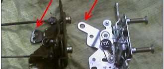
- Gate valves driven by an electric motor;
- Shut-off valves driven by a solenoid.
The design of gate valves is simple. They are based on a plastic molded body with pipes, inside of which there is a rotating plate in the form of a solid sector or a sector with holes the size of the pipes. A compact electric motor with a simple gear reducer is installed on the housing, with the help of which the plate rotates. In faucets with two nozzles (double-circuit), both nozzles are located opposite each other, with a plate between them. Three-way faucets have an inlet on one side and two outlets on the other.
The heater valve with an electric motor works as follows. When the heater is turned off, the valve plate is located between the pipes, blocking the flow of liquid - in this case, hot liquid does not flow into the heater radiator, and the interior heating system does not work. If it is necessary to turn on the stove, the driver presses a button on the dashboard, current is supplied to the electric motor of the faucet, it turns the plate and opens the path of coolant - the heater radiator heats up, the interior heating system begins to work. To turn off the heater, the driver presses the button again, all processes occur in reverse order, and the heater turns off.
A heater tap with three pipes also works easily if there is a bypass in the heating system. When the heater is turned off, the rotary plate is in such a position that the coolant passes through the tap and through the exhaust pipe enters the inlet of the engine cooling system (to the pump). When the heater is turned on, the plate rotates, closes one outlet pipe and opens the second - now the fluid flow freely passes into the heater radiator, and from it enters the exhaust pipe and the inlet of the engine cooling system. When the stove is turned off, all processes occur in reverse order.
The design of shut-off solenoid valves is different. They are based on a plastic case, inside of which there is a lifting valve in the form of a truncated cone. In the closed position, the valve sits on its seat, blocking the flow of liquid. The valve is connected via a rod to the solenoid armature, which is mounted on the valve body. Double-circuit valves can be single- or double-solenoid. In the first case, both locking elements are located on the solenoid rod, in the second, each locking element is controlled by its own solenoid.
The operation of the heater solenoid valve is also simple. The valves are normally open - without voltage on the solenoid, the valve is raised by a spring, the channel is open. When the engine starts, voltage is applied to the solenoid and the valve closes. When the stove is turned on, the solenoid is de-energized, the tap opens and supplies hot liquid to the heating radiator. When the stove is turned off, voltage is supplied to the solenoid again and the tap closes. A dual-circuit valve works in a similar way, however, one of its circuits is always closed when the ignition is turned on - this prevents the supply of coolant to the heater radiator; the liquid flows through the bypass. When the heater is turned on, the circuits switch, the coolant flows to the heater radiator, and when the heater is turned off, the valve returns to its original position. Both solenoids of a double-circuit valve never open or close at the same time (except during a complete blackout, when both valves are open).
GAZ 31 10 › Logbook › connecting the electric heater valve gas 31107
Hi all!
This post will not be very long, and in it I will tell you how I connected the gas heater electric tap 31107, what tap I used, what pipes, etc. let's go) the first thing I asked myself was which faucet to use - with two fittings or three. As I studied, I found out that cars with ZMZ 406 engines were equipped with double taps, and Chryslers with triple taps. True, I still don’t understand what this is connected with, because, in fact, the triple tap is a modified double tap, which did not stupidly shut off the flow to the radiator, but allowed the flow of antifreeze to bypass, in other words, the same thing, only a more competent design ) and, accordingly, I chose the triple option.
I bought the faucet itself and a set of pipes for the Volga and Chrysler. Then, by chance, a friend came into my garage with just such a car. Well, by chance, I used the pipes on the faucet “in the original way”)
Then I tried to understand the diagram, how it works, which fitting is responsible for what. seems to have given birth