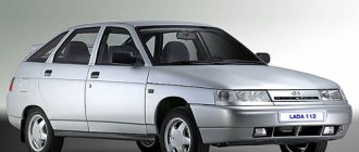
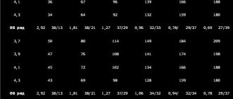
Fuse box diagram and location on VAZ-2114, 2115 and 2113
Remember one important thing, before you start disassembling the stove, wiper, headlight or anything else - make sure that the fuse responsible for this circuit has not blown
And in addition to the fuse, make sure that power is supplied to the non-working unit, because the mounting block and wiring of the car can eventually fail due to external factors and influences. The wire can most often suffer mechanical damage, the connectors can oxidize, but a track in the fuse block can burn out or even some of the conductive elements simply rot into dust.
By the way, it’s not for nothing that we focus attention on the latter - the location of the fuse box in the “chisel-samar” family is not entirely successful, water often gets on it, and due to the design features and its poor protection from moisture, various troubles are practically “guaranteed” by the manufacturer.
Today we will look at the diagram and location of fuses and relays VAZ 2113, 2114, 2115
The fuel pump does not work on the Lada Kalina
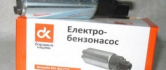
Replacing the fuel pump for VAZ 2113, 2114, 2115
The electric fuel pump, located in the gas tank of a Lada Kalina passenger car, can be considered the heart of the fuel injection engine power system. It is he who creates the necessary pressure in the ramp, the magnitude of which determines the operation of the electromagnetic injectors. The controller controls turning the fuel pump on and off. When the driver turns the key to the “ignition on” position, voltage is supplied to the fuel pump terminals for 3-5 seconds through the main relay. And as soon as the engine crankshaft begins to rotate, then, based on the signal from the DPKV sensor, the controller turns on the fuel pump relay and the voltage to its terminals goes through the contacts of this relay.
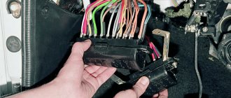
As you know, all electrical circuits in a car’s electrical wiring are protected by fuses, and if the fuel pump does not want to turn on, then they are the first to be checked. You can find a fifteen-amp fuse that protects the fuel pump circuit in the additional mounting block located next to the cigarette lighter. In order to open its cover, you will need a flat-head screwdriver. This block has four fuse slots. If they are in the first, second and third sockets, then you will need to check the middle fuse, since it is the one that protects the fuel pump circuit.
Having found out that this fuse is intact, the next step is to check the fuel pump relay. It is located behind the air duct cover located at the front passenger's feet. To remove it, you will have to unscrew one screw. Next, unscrew the nut securing the L-shaped metal plate and pull it out along with the four relays attached to it. The fuel pump relay is attached to the bottom of the plate, and the middle one of the three that is on the top of the plate is called the main relay. We check the functionality of the relay by replacing it with a known-good relay.
If checking the fuse and relay did not give the desired results, then by applying voltage directly from the battery terminals to the fuel pump terminals (gray wire plus, black wire minus) we check whether the fuel pump will work. If it turns on, then the fault will need to be looked for either in the absence of contact in the wire going to ground, or in a break in the wire going from the fuel pump relay to its block. A break in the gray wire is possible at the feet of the rear passengers, since the harness of 4 wires to the fuel pump block goes under the carpet, in the middle of the cabin.
helping-auto.ru
VAZ 2114 fuse mounting block diagram
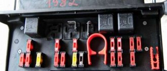
The fuse box in the VAZ-2114 is located under the hood, to the left in the direction of travel of the car, on the edge under the left wiper you will see a black box. To open it, you need to move two latches on the left. We remove the cover, there are relays and fuses.
There is a marking on the inside of the cover indicating the purpose of the relays and fuses.
Below is the purpose of all relays and fuses in the VAZ-2113 and 2114
| K1 | Electric fan relay |
| K2 | Relay-breaker for direction indicators and hazard warning lights |
| K3 | Wiper relay |
| K4 | Relay for monitoring the health of brake lamps and side lights |
| K5 | Power window relay |
| K6 | Horn relay |
| K7 | Heated rear window relay |
| K8 | High beam relay |
| K9 | low beam headlight relay |
Circuits protected by fuses
Cigarette lighter fuse VAZ 2114.
Relay for turning on the heated rear window (contacts). Rear window heating element.
| Fuse no. | Protected Circuits |
| F1(20A) | Relay for turning on rear fog lights. Rear fog lamps. Rear fog lamp activation indicator |
| F2(10A) | Turn signal lamps. Relay-breaker for direction indicators and hazard warning lights (in hazard warning mode). Hazard warning lamp |
| F3(10A) | Interior lighting. Individual interior lighting lamp. Ignition switch illumination lamp. Brake light bulbs. Trip computer |
| F4(20A) | |
| F5(20A) | Sound signal. Relay for turning on the sound signal (coil). Horn relay (contacts), Relay switching of the electric fan (contacts). Cooling fan motor |
| F6(30A) | Power window switches. Electric windows. Power window relay (contacts) |
| F7(20A) | Heater motor. Washer motor. Rear window washer motor. Rear window wiper motor. Electric windshield wiper relay (winding). Glove compartment lamp |
| F8(7.5A) | Right fog lamp |
| F9(7.5A) | Left fog lamp. Fog light relay (contacts) |
| F10(7.5A) | Turn indicators in turn signal mode and corresponding indicator lamp. Fan motor activation relay (winding). Indicator lamp for fuel reserve, oil pressure, parking brake, brake fluid level. Battery charge indicator lamp. Instrument cluster.Voltmeter. Carburetor electro-pneumatic valve control system. Parking brake warning light relay |
| F11(7.5A) | Side lamps on the starboard side |
| F12(7.5A) | Right headlight (low beam) |
| F13(7.5A) | Left headlight (low beam) |
| F14(7.5A) | Left headlight (high beam). Indicator lamp for turning on the high beam headlights. |
| F15(7.5A) | Right headlight (high beam). |
| F16(15A) | Relay-breaker for direction indicators and hazard warning lights (in direction indicator mode). |
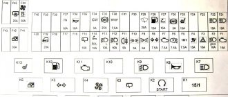
Connection diagram inside the VAZ-2114 and VAZ-2115 fuse box
(the outer number in the designation of the wire tip is the number of the block, and the inner number is the conventional number of the plug)
Why does the fuel pump turn off after warming up the engine on a VAZ 2114
Where is the gazelle fuel pump fuse located?
There is a problem, I don’t understand what’s wrong! The engine starts and runs normally, without any complaints. When the engine warms up, after a while the fuel pump turns off and does not respond to the ignition. It sits for 15-20 minutes and starts working again. What is the problem?
It is impossible to say exactly what the problem is that the fuel pump on the VAZ 2114 turns off after the engine warms up due to insufficient description, and yet we will consider options for what could cause this to happen.
The reasons for this can be divided into two parts - mechanical and electrical. Moreover, often one part can become a consequence of the second.
One of the simplest malfunctions that can give this result is a clogged fuel tank ventilation system. The tank lid is not airtight; it has drainage holes through which air passes. Everything is very simple here - air is needed so that a vacuum is not created in the tank as fuel is consumed. If the drainage holes are clogged, as the vacuum in the tank increases due to insufficient air supply, it will be more difficult for the pump to pump fuel into the system. This leads to an increase in the load on it and on the relay for its activation. When the critical load is reached, the relay simply turns off the pump.
And now how everything happens on a car: while the car is standing, air still penetrates the tank and the pressure in it equalizes. After starting the engine, the fuel pump actively pumps fuel, and since air does not flow in the required quantity, a vacuum appears. As the engine warms up, the vacuum increases and the load on the fuel pump and relay increases. To prevent the pump from failing at “one fine moment,” the relay turns off the power to the circuit.
Once you stand for 15-20 minutes, air enters the tank again, equalizing the pressure, and the whole cycle begins again.
A clogged fuel inlet grid of the fuel pump can give approximately the same result. But here everything happens not because of a lack of air, but because the pump needs to supply a certain amount of fuel, and it is very difficult to do this through a clogged mesh. It starts to work under load and the relay turns off the power after a while. This can also happen due to a clogged fuel filter.
There may also be problems with the fuel pump itself. Burnt wires connecting to it, insufficient weight, wear or damage to the electric motor creates an increased load on the fuel pump relay, which causes it to operate after a certain time.
After the engine stalls, you must immediately find its relay and check its temperature with your hand. If the element is very hot, then this is a signal that the entire circuit is working under heavy load. But what causes the heating still needs to be determined.
It is located on the VAZ 2114 on the passenger side, under the side decorative panel of the center console. There are three relays and fuses for them. The fuel pump relay is installed in the middle.
When checking the temperature, you should immediately evaluate the condition of the fuse, as well as the contact of the relay itself in the seat. By the way, this element can also fail, causing its operation to be incorrect. It’s easy to check its functionality; just close its contacts immediately after the engine stops. If the fuel pump starts to work, the relay must be replaced.
If everything is in order with this element, and a malfunction appears, then the cause should be sought in the components of the fuel system. The pump performance and filter throughput are checked. Indeed, due to excessive load on the pump due to a malfunction, clogged filter, fuel inlet mesh or tank ventilation system, the relay will turn off the pump after a certain time to prevent burnout.
Another item to check is the crankshaft position sensor. Initially, it may seem that the DPKV has nothing to do with the fuel supply system, but this is not so. Indeed, based on the readings of this element, the electronic unit controls the power system and the fuel supply circuit too. If the wiring to the sensor is not operating correctly or is damaged, the unit may turn off the power to the pump at certain moments.
In general, when searching for the cause, you should start from the relay and fuse, and then check both the mechanical and electrical components of the circuit of the fuel supply elements.
We recommend
- Replacing the alternator belt on a VAZ 2114
- Self-replacement of the oil pressure sensor on a VAZ 2114
- Designation of icons on the instrument panel of the VAZ 2114
- Correct timing chain tension on VAZ 2107
Connection diagram of the VAZ 2114 mounting block
(the outer number in the designation of the wire tip is the number of the block, and the inner number is the conventional number of the plug): K1 – relay for turning on the headlight cleaners; K2 – relay-interrupter for direction indicators and hazard warning lights; K3 – windshield wiper relay; K4 – lamp health monitoring relay; K5 – power window relay; K6 – relay for turning on sound signals; K7 – relay for turning on the heated rear window; K8 – headlight high beam relay; K9 – relay for low beam headlights; F1-F20 – fuses
Replacing the starter switch relay on VAZ 2108, VAZ 2109, VAZ 21099
Welcome! Starter activation relay - many will now think that we are talking about a retractor relay, in fact this is not so, in total the starter has two relays, one that turns it on and the second that extends the bendix and pushes its gear onto the crankshaft pulley (The second is the same retractor relay), if the first one fails (happens rarely, mainly due to overloads on it or due to faulty wiring), you will not be able to start the starter and therefore the car will not start; if the second one fails, there will be a little another situation, namely, the car may also not start and the clicking will occur when the key is turned, but this can be said even less, but if this relay fails completely and does not return the bendix to its reverse position, then the following will happen: When you turn the key, the starter will start turning the car's engine and eventually it will start, but when you return the key after the engine has started in the reverse position, the bendix on the starter will not come back (the solenoid relay does not work) and in a very short time the starter will become unusable .
Note! To change the relay, which is only responsible for turning on the starter, you need to stock up on: Only one “8” wrench, for the most part you don’t need to take anything else, but maybe one more wrench so that, just in case, you can remove the minus terminal from the battery!
Summary:
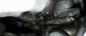
Where is the starter relay located? It is located in the engine compartment and is attached there to the car body using one single nut; in the photo below this relay is indicated by a red arrow, and the blue arrow shows the air pipe behind which this relay is located.
When do you need to change the starter relay? There are some people who either don’t know the electrical part of their car well, or simply never look at this relay (They say it lasts forever and never breaks), we just want to say that many people, when they see that their car won’t start with the key, they immediately jump into the starter, they remove it at the beginning, then replace the parts on it, remember for the future, you should always start with small and easily accessible things and only then go to hard-to-reach things and check them and change them if a malfunction is detected.
Note! If the starter relay fails, as we have already said, the car will not start and thereby respond to turns of the key in the ignition switch, the same will happen if the battery is weakly charged, and therefore if you suspect it, either charge it or change it to a new one if it is already very worn out, in addition, exactly the same situation (the car will not start) can occur due to the ignition switch, namely because of its contact group, but on cars with a starter relay, this rarely happens, because that the relay also unloads the contacts at the ignition switch and thus the contacts are less likely to burn out, but you can still read about how to check the contact group of the lock in the article entitled: “Replacing the ignition switch and its contact group on a VAZ”!
How to replace the starter switch relay on a VAZ 2108-VAZ 21099?
1. If you carefully read the above text, you will immediately guess how to remove this relay, but we will still instruct you, find this relay in your car (the location is shown in the photo above), you see a block of wires connected to it, then disconnect it, and after it is removed and set aside, take a wrench in your hands and unscrew the relay mounting nut with it and then remove it, by the way, if the work is done in the rain or in very wet weather or if you are simply afraid of a short circuit in the wiring (B In this case, all the wiring will burn out and will require replacement), then protect yourself by disconnecting the wire from the minus terminal on the battery; if you don’t know how to do this, then study “this article”, it says everything in the first paragraph.
Note! To check whether the relay is working or not (We don’t recommend buying a new relay just like that, always check everything), you can use two different methods, the first is that you have to remove the cover from the mounting block and pull out from there a relay with exactly the same marking as you have a relay for turning on the starter, after removing these two relays, replace these two relays and try to start the car, if it doesn’t start, then it’s not the relay and you need to look for the problem either in the starter itself or in the ignition switch, the second method implies that you will find the wire bring the jumper (Indicated by a blue arrow, the wire can also be used) and its conclusions to the wire block, namely to its contacts “30” and “87” (These are the lower and upper contacts of the block, take a closer look at the relay on it, they are marked or for clarity, take a look in the photo they are indicated by a red arrow, although there is a block from a completely different car, but it is almost the same and on it you can understand where these two contacts are located), if the car starts immediately (Don’t forget to remove the jumper when it starts to start) then it’s all in relay, if not, then look further (When you do the second method, do not forget to turn the key in the ignition until all the devices light up)!
Additional video clip: For more detailed information about checking the relay using the classic example, see the videos below:
Electrical diagram of VAZ 2115 – 20 cars (left half):
1 – headlights; 2 – fog lights; 3 – air temperature sensor; 4 – electric motor of the engine cooling system fan; 5 – blocks connected to the wiring harness of the ignition system; 6 – engine compartment lamp switch; 7 – block for connection to a single-wire type audio signal; 8 – sound signal; 9 – washer fluid level sensor; 10 – front brake pad wear sensors; 11 – oil level sensor; 12 – generator; 13 – engine compartment lamp; 14 – coolant temperature indicator sensor; 15 – starter; 16 – battery; 17 – relay for turning on fog lights; 18 – coolant level sensor; 19 – brake fluid level sensor; 20 – reverse light switch; 21 – windshield wiper gearmotor; 22 – oil pressure warning lamp sensor; 23 – block for connecting to the rear window washer electric motor; 24 – windshield washer electric motor; 25 – instrument cluster; 26 – mounting block. Conventional numbering of plugs in blocks: A - block headlights; B — electric fuel pump block; C — blocks of the mounting block, ignition switch, windshield wiper gearmotor; D — interior lamp
Lada 2115 › Logbook › Algorithm for troubleshooting an electric fuel pump
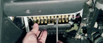
Hello to all subscribers! One of the common situations that happens, usually unexpectedly, is that the usual buzzing of the electric fuel pump in the rear of the car is absent when the ignition is turned on. As a result, the car engine refuses to start. I present an algorithm of actions if such a disaster suddenly happens. To begin with: photo 1 shows a fragment of the electrical circuit of the fuel pump.
Attention, working with electrical equipment is dangerous. If you are unsure, seek the help of a qualified professional.
First of all, the driver should first remove the side console on the passenger side (there are 3 relays with fuses there). Our electric fuel pump relay is the lower one. (Some cars from 2007 have 2 relays, but the fuel pump relay is the top one - see the repair manual). Directly above the bottom relay is our fuse. The first step is to make sure that this fuse is working properly (photo stage 1).
If the fuse is working and its contacts and its connector are not oxidized, then you need to make sure that the relay is working properly. You can immediately install a known-good relay and turn on the ignition. If the situation is corrected, then install the side console and have a good trip. If nothing has changed, then it is necessary to determine where the problem arose. To do this, you need to have a voltmeter or multimeter or a probe. But we will not determine the voltage value with a probe, and in this situation you need to know the voltage value - I’ll tell you why later. The second step (photo step 2) is to determine whether there is control voltage at the fuel pump relay. We connect the multimeter, turn on the ignition and determine the voltage value. If there is no voltage, then there is an open circuit coming from the main relay or from the ECU. If there is tension, then move on.
Stage 3 (photo stage 3) is to determine whether the power goes further directly to the fuel pump itself. If the power does not come out, the culprit is most likely the relay due to possibly burnt contacts. If the voltage goes away, but its value is 10 volts, then most likely the relay contacts are also burnt. At this voltage, the pump motor will not start. We change the relay and check. If the power goes further and its value is 12 Volts, then the culprit is the wires going to the electric motor of the pump or the pump itself.
Next you will have to remove the rear seat to get to the electric fuel pump. We remove the hatch and see the fuel pump chip. There are 3 wires on the chip: 1-minus, 2-plus of the fuel level sensor, 3-plus of the fuel pump itself. Unfortunately, I won’t tell you the sequence and location on the chip yet. In any case, when the ignition is on, there should be 2 pluses and one minus. In photo 4 (photo stage 4) we connect one by one to the contacts of the fuel pump chip and look at the presence and magnitude of voltage. If there is voltage, then the culprit is the electric fuel pump itself, and without removing it, most likely the cause cannot be eliminated.
Be careful with electricians and remember that the fuel pump control circuit can also break a faulty security alarm relay. Smooth roads everyone.
VAZ 2115 fuses (Mounting block)
A fairly common type of breakdown in cars is the shutdown of the vehicle's electrical equipment. Quite often this is due to a blown fuse. To quickly fix such a problem, you need to know exactly where the fuse is located, which is responsible for the disabled electronic component of the car, as well as how to replace it.
Where are the fuses located?
No vehicle is designed to have fuses scattered in different places. In every car, including the VAZ 2115, all fuses are located in a special block called a fuse block.
Like most cars, the VAZ 2115 has two fuse blocks. One of them is located in the car's interior, under the dashboard, and the second in the engine compartment, near the left glass.
What fuses are located on the VAZ 2115
Let us recall that in the previous article we looked at malfunctions of the ignition module on the VAZ 2115, its repair and replacement with our own hands.
Each fuse, which is located in the vehicle fuse box, has its own marking, by which you can determine what it is responsible for:
1. “K1” - this element of the fuse block is responsible for the headlight cleaning system relay. 2. “K2” - that element of the fuse block is responsible for the relay of the system for switching turning lights, as well as for the alarm system. 3. “K3” – is responsible for the windshield cleaning system. 4. “K4” – is responsible for monitoring the performance of the lamps. 5. “K5” – is responsible for the electric window system. 6. “K6” – is responsible for sound signals. 7. “K7” – is responsible for the rear window heating system. 8. “K8” – is responsible for illuminating the roadway in high beam mode. 9. “K9” – is responsible for illuminating the roadway in low beam mode. 10. “F1” – “F20” are special fuses.
The design of the fuse box on the VAZ 2115
The interior fuse box has a slightly different structure than the one located under the hood. It includes an electronic control unit, three fuses, and three relays.
Just like in the fuse box located in the engine compartment, here each fuse has its own purpose.
If we describe them from top to bottom, we get the following:
1. The fuse that controls the fuel pump. Its current strength is 15 amperes. 2. The fuse, which is responsible for the electric radiator fan relay, the valve located on the adsorber purge, as well as for the mass air flow sensor, DC and DC. The amperage of this fuse is 7.5 amps. 3. Fuse that controls the ECU. The current on this fuse is 7.5 amps.
Also, in order to fully understand fuse blocks, you should know about the relays that are located in the interior fuse block.
Below you can find their description from top to bottom:
1. A relay that is responsible for turning on the fuel pump. 2. A relay that is responsible for turning on the electric radiator fan of the cooling system. 3. Main relay.
How to identify a blown fuse and replace it?
As we said above, each fuse that is located in the car is responsible for its own electrical equipment. In this regard, you only need to look at the cover of the fuse box, and according to the diagram that is printed on it, determine the location of the required fuse.
To get to the fuses themselves, just press the latch with one hand and open the fuse box cover with the other.
How can I be sure the fuse is blown?
There are two main ways to evaluate the performance of a fuse. The first, simpler, but less reliable - “by eye”. To do this, pull out the fuse and see if its middle part is intact.
The second method of checking the fuse is better. You need to turn on the ignition and measure the voltage at the fuse contacts one by one. If one has it, but the other does not, then the fuse has blown.
In conclusion, I would like to note that if your fuses blow quite often, then you should check all the wiring of the vehicle. This requires serious experience and specific knowledge. If you do not have them, then it is better to contact an experienced specialist at a service station.
where is the VAZ 2115 ignition switch unloading relay located?
where is the VAZ 2115 ignition switch unloading relay located?
Currently, the vast majority of cars use the car body (vehicle) as a common wire for most electricity consumers. The body is therefore called the mass (foreground, ground) of the car. If any of the connections to the mass becomes unreliable, miracles begin. The simplest example of this is the blinking of all the lamps in the rear light.
We turn on the turn signal, and it starts blinking with the brake light or reverse light. At the same time, at the required consumer, the voltage is two to three times different from the required 12-14 volts, and at the unnecessary (not turned on), on the contrary, quite sufficient voltage appears for its operation. This is with light bulbs. What if this starts in the Electronic Engine Control System (ECM)? Then the engine may begin to spontaneously change its operating mode - from gaining high speeds to stalling. I’ll try to describe the places where the loss of a reliable connection to ground is most likely, and the glitches that appear in this case. I ask you to forgive me in advance for the sometimes strange and unusual names of components and car parts, but since I work at a VAZ warranty station, the situation obliges me.
I'll start, perhaps, with the Rechargeable Battery (AB). In modern VAZ cars, a double wire comes off the negative terminal of the battery. Its thick part, about the thickness of a little finger, connects the negative battery and the engine. If the contact of this wire is unreliable, there may be a deterioration in the battery charge, a decrease in the starter rotation speed when starting, as well as problems in the ECM system, because
The minus comes from the engine, from the studs on which the ignition distributor hung on carburetor cars. First of all, you should check the tightness of both nuts, between which the wire tip is attached to the engine. First, loosen the outer nut, tighten the nut under the tip, and then tighten the outer one back. The thin wire connecting the battery negative and the car body is the main connection for all electricity consumers in the car, and in carburetor modifications also for the engine. You should check the tightness of both the M6 bolt directly on the battery terminal and the M8 nut on the body. The location on the body depends on the make of the vehicle.
https://chiptuner. Ru/image/gnd/gnd_2110_01. Jpg VAZ 2110 https://chiptuner. Ru/image/gnd/gnd_2114_01.
Jpg VAZ 2108-99, 13-15 https://chiptuner. Ru/image/gnd/gnd_21213_01. Jpg VAZ 21213 https://chiptuner.
Ru/image/gnd/gnd_k11183. Jpg VAZ 11183 https://chiptuner. Ru/image/gnd/sniva_batt. Jpg Chevrolet - Niva https://chiptuner.
Ru/image/gnd/pr_01. Jpg Priora – battery https://chiptuner. Ru/image/gnd/pr_02. Jpg Priora battery mass https://chiptuner. Ru/image/gnd/pr_03.
Jpg Protection of the main power circuits on the Priora Family 2108-9 and 13-15 1.5L ECM mass is taken from the engine, from two M6 bolts securing the plug on the right side of the cylinder head. For carburetor cars, the ignition distributor was attached there. Family of vehicles 2113-15 1.5 and 1.6L with new generation controllers Bosch 7. 9. 7 or January 7. 2, the ECM connection to ground is located on a welded pin securing the metal frame of the central console of the instrument panel to the floor tunnel , through a metal strip with two side lugs on the left and right (Inside the center console, approximately under the ashtray).
Unfortunately, as practice has shown, there is no castle washer under the bar. Because of this, given that the stud itself is painted during the manufacturing process of the vehicle, and is practically not tightened with the corresponding nut, over time, a voltage drift appears in the ADC channels of the DTOZH, TPS and MAF sensors when the radiator electric fan is turned on. As a result, we have a jump in engine speed when the fan is turned on. Treatment methods are described in the FAQ. Thus, in this case, poor electrical contact between the body and the battery negative is also very critical. (Cm.
Higher). Family 2110-12, 1.5L. The ECM weight is taken from two M6 bolts located on the left side of the cylinder head. Family 21114, 21124 1.6L, with new generation Bosch 7.9 controllers.
7 or January 7. 2. There is already one M6 bolt in the head. The ground is taken from it only for all four ignition coils, and the ground for the ECM is taken in the cabin, from the welded stud on the ECM mounting bracket, behind the left screen of the center console. In turn, the mass is supplied to the bracket through a pin welded to the engine shield in the middle.
The nut on this stud is usually not tightened. If there is insufficient contact in these connections, voltage drift in the ADC channels of the DTOZH, TPS, and MAF sensors is possible when the radiator electric fan is turned on. As a result, we have a jump in engine speed when the fan is turned on. Treatment methods are described in the FAQ. Thus, in this case, poor electrical contact between the body and the battery negative is also very critical. (Cm.
Higher). Niva family with Bosch MP 7.0 controller. The mass of the ECM is taken from the engine, from the bolts securing the plug, in place of the ignition distributor - distributor, next to the ignition module.
Niva family with Bosch M controller 7. 9. 7. The mass of the ECM is taken, which has already become typical for the new generation of controllers from the car body. In this particular case, directly from the studs of its fastening. However, I personally didn’t really like this method due to the fact that the terminal crimped at the end of the wire is much thicker than necessary for the castle washer to be evenly pressed against the car body around the stud.
Therefore, I left the washer in place between the body and the controller, but moved the terminal directly under the controller mounting nut. On Niva 21214, the mass is taken from 2 sides of the block. Next, both wires enter the common harness and go to the ECU connector.
In front of the connector there are twists for each brown wire where the mass is distributed for the remaining sensors and the ECU itself. Chevy Niva family with Bosch MP 7 controller. 0. The ECM mass is taken from the engine block, from the M8 studs located in its lower left part, under the ignition module. In the photo above it you can see the mounting studs for the MZ (it has been removed).
Family 2104-07 classic with old controllers. The ECM weight is taken from the bolt that tightens the bracket securing the ignition module to the engine block. VAZ 11183 Kalina family.
The ECM ground is located on the right side of the engine, on the intake manifold mounting bracket. https://chiptuner. Ru/image/gnd/gnd_esud_2111. Jpg https://chiptuner.
Ru/image/gnd/gnd_ign_21124. Jpg https://chiptuner. Ru/image/gnd/gnd_797. Jpg https://chiptuner. Ru/image/gnd/gnd_2109.
Jpg https://chiptuner. Ru/image/gnd/sniva_esud. Jpg https://chiptuner. Ru/image/gnd/gnd_esud_11183. Jpg https://chiptuner. Ru/image/gnd/niva_ecu_797.
Jpg https://chiptuner. Ru/image/gnd/gnd_21214-1. Jpg https://chiptuner.
Ru/image/gnd/gnd_esud_21213. Jpg For the 2108-9 and 2113-15 families, the only connection point between the torpedo harness, the rear harness and the mounting relay and fuse box circuit is on the steering shaft amplifier, under the instrument cluster. If the contact in this connection is unreliable, deviations of the arrows of the temperature and fuel level indicators are possible when the side lights, turn indicators, sound signal, windshield washer, windshield wiper, etc. are turned on. For the lazy type of diagnosticians in the 2113-15 family, it is possible to throw the snot from the mass of the cigarette lighter onto a metal structure inside the center console of the instrument panel - a beard, with a wire with a cross-section no smaller than that going to the cigarette lighter. But only if the factory instrument panel is installed.
This can be determined by the presence of a fastening of the specified metal structure to the floor tunnel, a proprietary fastening of the ECM controller - using a plastic adapter between the controller and the metal structure and a fixed diagnostic connector in the standard place behind the decorative plug under the ashtray. For conscientious diagnosticians: be sure to securely tighten the standard bolt after removing the instrument cluster. The same family has another ground connection, the heater electric motor. It is located under the instrument panel, on the left side of the heater housing. For the 2110-12 1.5L and 21114, 21124 1.6L families, everything is different. There are more such connections there.
The first ground connection of the vehicle is located inside the instrument panel, on the top left of the relay and fuse mounting block, under the sound insulation. On cars of the first years of production, the ground wires to the welded stud were approached on top of the sound insulation, and then someone’s bright mind came up with the idea of hiding the wires under it. So access to the stud is very inconvenient and is only possible using a tube wrench or an extended 10mm socket.
If the connection in this place is insufficient, when the headlights or electric window motors are turned on, the windshield wiper and washer may turn on and the central door locking system may operate. The second connection is located on a welded stud, on the center console of the instrument panel, on the left side, above the left console screen, under the M6 nut. But even if this nut is tightened properly, and the problem remains, then we move on to the most important point of mass for the entire instrument panel, grounding the entire metal frame of the panel. This is a welded stud with M6 thread.
It is located on the lower, inner (cabin) side of the engine shield, in the middle. The nut screwed onto this stud also secures the bracket that secures the front part of the left screen of the console, which some diagnosticians and electricians mercilessly remove due to the fact that there are frequent cases of damage to the ECM harness or central locking system on this bracket. As a rule, the nut is tightened very, very mediocre.
If there is insufficient contact in this and the previous connection, when turning on the side lights, headlights and radiator fan motor, deviations of the temperature and fuel level indicator arrows are possible. In the NIVA family with all types of controllers, the mass of the torpedo harness is attached with a nut to the welded pin for fastening the relay bracket, and, as has become customary, it is tightened very loosely. This pin is located behind the standard fuse block.
The mass of the engine compartment harness is attached to one of the welded studs securing the brake fluid reservoir. The mass from both radiator cooling fans is also screwed there. In a Chevy Niva car, the main connection point of the harnesses to ground is in the upper left part of the engine shield on the passenger compartment side, also on a welded stud. To access the connection, you need to unscrew the decorative cover covering the mounting relay and fuse block and this block itself. Another problem area of the Chevy Niva is the power mass of the battery, which is screwed to the body next to the chain tensioner. There are also 2 ground wires on the ECU mounting bracket.
In the photo, the ECU has been removed for clarity. The VAZ 2104 - 07 family is a classic, the mass of the torpedo harness is attached to a welded pin behind the instrument cluster, along with the turn relay. https://chiptuner. Ru/image/gnd/gnd_2110_04. Jpg https://chiptuner.
Ru/image/gnd/gnd_2110_03. Jpg https://chiptuner. Ru/image/gnd/gnd_esud_21124. Jpg https://chiptuner. Ru/image/gnd/gnd_2110. Jpg https://chiptuner.
Ru/image/gnd/niva_cool_mass. Jpg https://chiptuner. Ru/image/gnd/niva_torp_mass. Jpg https://chiptuner. Ru/image/gnd/sniva_ecu. Jpg https://chiptuner.
Ru/image/gnd/gnd_shevi. Jpg https://chiptuner. Ru/image/gnd/gnd_clas_esud.
Jpg https://chiptuner. Ru/image/gnd/classm1. Jpg https://chiptuner. Ru/image/gnd/classm2. Jpg I would also like to note this important detail: absolutely all the studs to which the ground wire terminals are attached are painted at the factory along with the body, they do not have any protective coating other than a layer of paint and are therefore susceptible to corrosion when the paint is removed and there is no additional protective lubricant.
To ensure proper contact of these terminals with the body, the factory uses castle washers, which, unlike Grover washers, should not be between the terminal and the nut, but between the body and the terminal. With its sharp edges between the cut-out teeth, the washer with one side facing the body pierces the paintwork, and the other side facing the terminal firmly digs into it. The correct location of these washers should be the first thing to pay attention to when clients contact us about faults in electrical equipment after performing reinforcement work carried out during the process of tin-painting or other repairs.
In particular, when removing the bracket for fastening the air intake hose on the tenth family, which sits on the stud fastening the negative battery wire to the body, the specified washer must be located between the body and the bracket. In conclusion. If you have found a place with poor contact, take the time to separate all connections from each other, identify burnt or oxidized areas, and thoroughly clean and level all contacting surfaces before final assembly. Below is a small gallery of connecting mass power points on domestic car engines. https://chiptuner.
Ru/image/gnd/gnd_2110_02. Jpg https://chiptuner. Ru/image/gnd/gnd_21213_02.
Jpg https://chiptuner. Ru/image/gnd/gnd_21124. Jpg https://chiptuner. Ru/image/gnd/gnd_p11183. Jpg https://chiptuner. Ru/image/gnd/gnd_2114_02.
Jpg https://chiptuner. Ru/image/gnd/gnd_clas_en. Jpg https://chiptuner. Ru/image/gnd/gnd_clas_akb. Jpg https://chiptuner. Ru/image/gnd/sniva_bl.
Jpg Text and photo: I. N. Skrydlov, Lyubertsy (aka Aktuator) chiptuner. Ru.
Did you like the article? Share with friends:
VAZ 2115 fuses
The location of the mounting fuse block in the Lada Samara family car is different from previous modifications.
Where is it located: the main board is installed in the engine compartment, the additional module is in the central channel on the right.
The process of replacing fuses (hereinafter referred to as modules) is not at all complicated, similar to the VAZ 2110, 2112, but it requires attentiveness on the part of the technician. Violation of the installation technology, incorrect selection of the module leads to its overheating and short circuit.
If you encounter difficulties with replacement, contact a specialist service station.
Signs of a malfunction of the VAZ-2114 fuel pump
In the vast majority of cases, this unit fails due to low-quality gasoline. Determining that it is the fuel pump that is faulty is quite simple. The thing is that the signs of failure of this unit are very characteristic. These are, in particular:
- the car does not start, although the starter turns properly;
- tripling;
- At low speeds the engine growls.
The most common situation is when the car suddenly stalls, while there is enough fuel in the tank. At the same time, all attempts to start the engine again lead to nothing, although the starter turns properly. Of course, the problem could be, for example, in the spark plugs or in the electronic control unit. But often this indicates a failure of the fuel pump.
Problems with this unit are also indicated by engine tripping. Having made sure that all the spark plugs are in order and a spark is supplied to them, you can, in principle, proceed to inspecting the fuel pump. The thing is that if there are problems in its operation, the process of burning fuel in the cylinders does not occur correctly, and because of this, the engine begins to twitch, and quite sensitively. Another sign indicating a fuel pump malfunction is the “roar” of the engine at low speeds. This sound often appears when the low-purity filter is dirty.
In order to be completely sure that the problem is in the fuel pump, measure the pressure in the fuel rail. This can be done using a pressure gauge - the main thing is that its measuring range is small. The best option is up to 7 atmospheres. It is not advisable to use a larger range, since the errors can be quite serious.
Relay-breaker layout diagram
| Name | What is it responsible for/what does it provide? |
| K 1 | Headlight wiper relay |
| K2 | Turn signals, hazard warning lights |
| K 3 | Windscreen wipers |
| K 4 | Controlling the operation of dashboard lamps |
| K5 | Window lifters |
| K 6 | Sound signal |
| K 7 | Heated rear window |
| K 8 | Long range lighting |
| K9 | Low lighting |
How to distinguish fuses from each other on a diagram
On the VAZ-2115, car fuses, in addition to special markings, are painted in different colors. This is done for convenience: each specific color corresponds to one of the calculated current values in accordance with GOST conditions:
- gray – 2 A;
- pink – 4 A;
- orange – 5 A;
- brown - 7.5 A;
- red – 10 A;
- blue or blue - 15 A;
- yellow – 20 A;
- white – 25 A;
- green – 30 A.
On the VAZ-2115 fuse diagram, 20 elements are marked, each of which corresponds to a marking with the English letter “F” and a digital designation. It is by the alphanumeric marking that you can find the desired fuse, which is responsible for a specific section of the conductive circuit:
- Rear fog lights – F1.
- Turn signal repeaters – F2.
- Car interior lighting – F3.
- Rear window heating – F4.
- Radiator fan, signal – F5.
- Electric windows – F6.
- Cigarette lighter, washer motor – F7.
- Front fog lights – F8-F9.
- Left-hand dimensions, front and rear license plate lighting, instrument panel lighting - F10.
- Right-hand dimensions – F11.
- Low beam headlights – F12-F13.
- Driving lights – F14-F15.
- Instrument panel indicator lamps – F16.
- Reserve safety elements for VAZ-2115 injector – F17-F20.
But in addition to the listed main safety elements, which are located in the mounting block of the engine compartment (on the left side under the windshield), the VAZ-2115 has several additional fuses. Additional safety elements are located in the vehicle interior itself - under the dashboard under the glove compartment on the passenger side. This arrangement of three additional fuses is due to their functional feature - they are responsible for the operation of the main engine systems. Such systems include:
- power supply for the gasoline pump – top location of safety elements;
- cooling fan, canister purge valve, speed sensor, crankshaft position and mass air flow sensor - middle location;
- central relay, ECU - bottom location.
As you can see, all of the above automotive parts perform important functions, so the safety elements for them must be protected from external influences, mechanical damage and negative environmental influences.
Fuse installation diagram for VAZ 2115 (injector, 8 valves)
| Marking/amperage | What is he responsible for? |
| F (F-1) / 10 | Rear fog lights, headlight washer motor, fluid pump |
| F (F-2) / 10 | Turn signals. emergency gang |
| F (F-3) / 7.5 | Interior lighting, trunk lighting, on-board computer, clock |
| F (F-4) / 20 | Car socket, heated rear window |
| F (F-5) / 20 | Signal, cooling fan |
| F (F-6) / 30 | Window lifters |
| F (F-7) / 30 | Oven heater, cigarette lighter, heated rear window, glove compartment lighting |
| F (F-8) / 7.5 | Left side fog light |
| F (F-9) / 7.5 | Fog lamp on the right side |
| F (F-10) / 7.5 | Left-hand side lights, license plate lights, engine compartment lights |
| F (F-11) / 7.5 | Right-hand dimensions |
| F (F-12) / 7.5 | Low illumination on the right side |
| F (F-13) / 7.5 | Low beam on the left side |
| F (F-14) / 7.5 | Left-hand high beam |
| F (F-15) / 7.5 | High beam on the right side |
| F (F-16) / 15 | Hazard alarm, heater, brake light |
| F (F-17) / 7.5 | To the fuel pump, to the wipers, to reverse |
| F (F-18) / 25 | central locking |
| F (F-19) / 10 | Reservation |
| F (F-20) / 7.5 | Reservation |
The price of a complete power supply starts from 2300 rubles, melting elements from 100 rubles, a set from 400 - 550 rubles.
Additional power relay modules are installed in the central channel, under the dashboard. To get to the parts, first remove the plastic cover.
Fuel pump VAZ 2106
A car fuel pump is considered the most important element of the entire gasoline supply system. Actually, the pump is necessary in order to pump fuel from the gas tank to the carburetor. After all, it is in the carburetor unit that the air-fuel mixture is formed, which is then supplied to the engine.
The fuel pump supplies fuel from the tank to the engine through special hoses.
Principle of operation
The main task of the fuel pump is to generate excess pressure in the fuel system under any engine operating mode. It is necessary to ensure that there is always a sufficient amount of gasoline in the carburetor float chamber.
Video: design and operation diagram of a gasoline pump
Which fuel pump is better for the “six”
The standard equipment of the “six” is a gasoline pump produced by DAAZ (Dimitrovgrad Automobile Unit Plant). In terms of its structure, it is a mechanical unit, which is equipped with a diaphragm drive. Three diaphragms are built into the design of the DAAZ fuel pump to ensure uninterrupted operation of the device.
The performance of a fuel pump of this brand is 60 liters per hour (on free drain). This volume is quite enough for optimal operation of the entire fuel distribution system on the VAZ 2106.
Initially, the “six” was equipped with DAAZ brand fuel pumps
A modern analogue of DAAZ is considered to be a petrol pump of the Pekar brand produced by the fuel equipment plant in Saratov. This pump has the same performance (60 l/h), but is considered more reliable due to its high tightness and resistance of the membrane elements to oil.
“Pekar” can be installed on a VAZ 2106 of any year of manufacture, but it became standard after 1990.
The Pekar fuel pump has the same performance as the DAAZ, but it is more modern and reliable
The gasoline pump on the VAZ 2106 is located under the hood. The device is fixed on the left side to the engine cylinder block. Fastening is carried out with studs with the obligatory use of a thermal spacer and an adjusting shim. This arrangement is very convenient, since if necessary, you can quickly find, remove and repair or replace the faulty part.
The fuel pump is located on the cylinder block on the left side
Common causes of fuse failures
- Natural factor - due to long-term operation of the technical device;
- Mechanical damage, accident, impact, collision;
- Short circuit in the circuit;
- Damage to insulation, oxidation of terminals, loosening of contacts;
- Water entering the mounting block, condensation formation, deformation due to high operating temperature.
Replacing fuses on a VAZ 2115
- Driver, head at “10”;
- Flat head screwdriver;
- A set of new modules;
- Plastic pliers for removing the relay block;
- Rags, additional lighting as needed.
- We turn off the engine, open the hood, remove the terminals from the battery;
- On the left side, closer to the windshield, there is a mounting block. Unscrew the two bolts around the perimeter;
- We disconnect two blocks with wires, remove the power supply assembly;
- We carry out troubleshooting and check the serviceability of all modules.
You can do this in two ways:
- Visually: checking each module for the integrity of the melting element;
- Using a multimeter: measuring the resistance at the end switches of the module without dismantling it.
Each method is applicable and effective.
After replacing the faulty fuses, we assemble the structure in the reverse order.
Some motorists practice the second method: without dismantling the mounting block. We remove the fuses one by one, check them for integrity, and replace them with new ones as necessary.
If you notice that a unit in your car has suddenly stopped working, do not rush to dismantle it and replace it with a new one. First of all, inspect the mounting block, check the modules for integrity. Most likely some kind of fuse has blown.
Only after replacing the module does not help eliminate the problem, proceed to diagnosing the equipment and checking the integrity of the electrical supply circuit.
Differences between starter and relay failure
In order not to confuse what exactly has failed - the starter or the solenoid relay, there is an excellent method for recognizing the “culprit”.
- Remove the starter, connect the negative terminal of the battery to ground;
- The design of the device has copper bolts and a tongue-shaped element;
- The positive wire from the battery is connected to this “tongue”;
- If there is contact, the solenoid relay clicks and starts working;
- If not, then you will have to go to the store for a new relay.
But there is one more very important point. Even if all the facts indicate that the starter or retractor relay is not working, another unit - the ignition switch - may still be the cause of ignition problems. Take the time to check its serviceability before buying new parts.
Recommendations for care and maintenance
- Buy original fuses. Domestic or foreign, it doesn’t matter;
- Install strictly in accordance with amperage ratings. Unacceptable with lower or higher current strength. In the first case, this will lead to damage to the module, in the second - to breakdown of the unit, which is attached to the fuse;
- Carefully check the quality of fixation of terminals and limit switches on the board. If loose, tighten and press with pliers. A spark can cause a fire and melting occurs;
- If moisture gets in or condensation forms inside the mounting block, remove the cover, dry it, and if necessary, blow it with a stream of compressed air.
Carry out preventive and diagnostic work in the fuse box with the battery terminals removed in order to prevent a short circuit in the circuit.
The average service life of fuses is 40 – 60 thousand km. The service life of foreign analogues is 10–15% longer. Before replacing, read the instructions and get advice from service station specialists.
Removing, installing and replacing the fuel pump
The first thing to keep in mind is that all work on the car’s fuel system must be carried out with the negative terminal of the battery disconnected. It would also be a good idea to do this with an empty fuel tank, especially since with the fuel module removed it becomes possible to clean the bottom of the gas tank from sediment.
The second thing it is advisable to do is to remove the pressure inside the fuel lines so as not to get a stream of gasoline in your face or into the interior of the car. This can be done using a measuring nipple on the fuel rail and a thin screwdriver.
Sequence of work
- Raise the rear sofa.
If there is a new assembled module in stock, install it in the reverse order. If it is necessary to replace individual components: the fuel pump itself, the level sensor or the primary filter mesh, we do this by disassembling the fuel module housing and removing the corresponding parts.
This procedure is unlikely to cause any difficulties - everything is quite obvious.
For a new type of fuel pump, you need a 10mm socket and a ratchet, similarly unscrew the ring in a circle and press out the fuel line clamps.
What is the VAZ 2114 ignition relay responsible for?
Below watch the video about replacing the ignition relay in a VAZ 2114 and express your opinion about it in the reviews of the article.
Video quality: SATRip
The video was uploaded to the admin from the user Avigdor: for immediate viewing on the portal.
To give the correct answer to the question Replacing the ignition relay in a VAZ 2114, you need to watch the video. After viewing, you will not need to seek help from specialists. Detailed instructions will help you solve your problems. Enjoy watching.
Humor on topic: - Tell me, Borya, is your relationship with my Alla really serious? - Roza Markovna, I beg you, our relationship is so serious that we have never smiled.
The engine control system circuits are protected by three fuses.
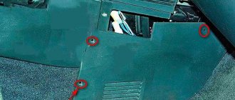
Location of relays and fuses for the engine management system under the instrument panel console
Note. The right trim of the instrument panel console has been removed (see “Instrument panel - removal”).
Engine management system relays and fuses:
1,2 and 6 - fuses (see table 8.4.3); 3 - main relay; 4 — relay for turning on the electric fan of the engine cooling system; 5 - fuel pump activation relay
The fuel pump does not work, the relay turns on.
Checking relay power.
In the case when the fuel pump relay turns on when the ignition is turned on, but the pump itself does not work, you need to check the power at terminal 87 of the fuel pump relay. To do this, touch terminal 87 of the relay socket with the output of the control lamp connected to the vehicle ground, and the lamp should light up. If the lamp does not light, it means the fuse has blown or there is a break in the wire.
If there is power at terminal 87, you should remove the relay from the socket, and instead place a jumper between pins 87 and 30. In this case, if the pump and connecting wires are working properly, the pump should start working and if this happens, the relay should be changed. If the pump does not start working, then, without removing the jumper, you need to touch the power wire on the fuel pump with a test lamp connected to the vehicle ground.
Checking the fuel pump power circuit.
If a submersible pump is installed on the car as part of the fuel module, you need to remove the connecting connector and touch one of the thick wires. When you touch one of them, the indicator lamp should light up. If the lamp does not light up on any of the wires, then it is necessary to eliminate the break in the wire from the fuel pump relay to the module connector or the pump itself, if the pump is of a remote type. One of the reasons for the break may be the anti-theft blocking of an installed non-standard alarm system.
In the case when the test lamp lights up on one of the thick wires of the connector or one of the terminals of the remote pump, you need to connect these terminals with a test lamp to each other. In this case, the control lamp should light up. If the lamp does not light, it is necessary to eliminate a break or poor contact in the wire connecting the pump to the vehicle ground.
If, when checking the wires and relay for turning on the fuel pump, no malfunction is detected, the electric motor of the fuel pump or its connection to the module connector is faulty. It is not difficult to find the cause by removing the fuel pump module from the tank. If there is poor contact with the connector, melting of the plugs will be visible. If melting is not noticed, then to check the pump itself, you can connect it to the battery. It should be taken into account that operating a submersible pump without liquid will damage the pump. A faulty pump should be replaced.
Hello to all subscribers! One of the common situations that happens, usually unexpectedly, is that the usual buzzing of the electric fuel pump in the rear of the car is absent when the ignition is turned on. As a result, the car engine refuses to start. I present an algorithm of actions if such a disaster suddenly happens. To begin with: photo 1 shows a fragment of the electrical circuit of the fuel pump.