Door harnesses
There are wires running through the cabin that connect to the door wiring - they ensure the operation of power windows, speakers, alarms, rear window heating, etc. Each line has a socket, thanks to which the door can be easily removed and replaced.
Let's note some features:
- each harness has wires going to the central locking moderator; in more advanced models, the rear doors have wires for the interior lighting and the window regulator;
- the driver's door harness goes to the buttons for the two power windows of yours and the passenger's;
- in the front doors there are wires going to the speakers that are located in them;
- The rear door harness is one of the most complex - it includes wires for the heated glass, wiper and washer gear, rear brake light, central locking and ground wires.
You can see door wiring diagrams in the picture. They all originate from the rear harness, which goes to the taillights.
Candle making options:
To increase productivity when creating these products, some technological features are used, which in theory can increase productivity, and as a result, the highest quality fuel combustion:
- Platinum coating. Allows you to increase the service life up to 50 thousand kilometers due to the fact that the surface becomes more resistant to the combustion products of the fuel mixture.
- Multi-contact spark plugs. Typically used in cars that are operated in regions with predominantly low temperatures. Such products make it possible to improve the starting of a cold car in the morning. In summer, it is recommended to replace them with regular ones.
Transferring the ignition module
In order for the ignition module to work better, it is moved to the engine compartment higher than it was originally located.
Before moving and installing additional parts, it is important to ensure that there are no foreign objects nearby. The wires are disconnected from the system only when the ignition is turned off. The main thing is not to touch them with your hands without any additional protection.
The same goes for completely disconnecting the batteries when the need arises. Transfer is classified as a simple operation.
The main thing is not to touch them with your hands without any additional protection. The same goes for completely disconnecting the batteries when the need arises. Transfers are classified as simple operations.
Installation is carried out in the reverse order compared to dismantling. Bending the standard bracket is the main solution that is used in such situations. Each master decides for himself which way is best to weld the bracket - you can easily achieve the effect when all its parts remain even.
Ignition coil malfunctions
The main types of ignition coil malfunctions include:
- A short circuit between the turns of any of the windings of the product.
- A break in the electrical circuit of the primary or secondary windings.
- Insulation breakdown of the secondary winding on the body of the device.
- There is a lubricant leak on the product cover.
- Defects on the device cover.
- Incorrect values of the measuring device when measuring the resistance value of the ignition coil of any winding.
With such above defects, the coil must be replaced. A qualitative check of the ignition coil is divided into several tests. These include:
- testing the product resistance in both circuits;
- testing the resistance of the device to the “mass” of the device.
To carry out the test, two conditions must be met: the external temperature must be in the range of 20-25 degrees Celsius and the presence of a measuring device - a megger. We connect the “crocodiles” of the device to the contacts of the product on the right and left and take measurements in the selected range. The winding resistance should be within the range of 0.4-0.5 Ohms. If the measurement value is different, the ignition coil must be replaced with an updated product. To carry out the test, you need to connect the alligator clips to connector “B” and to the central contact. At the previously determined temperature value of the atmosphere, the measuring device in the given register should show 4.5-5.5 kOhm. If the measurement value of the “nine” ignition coil is different, then the device must be replaced with an updated product. To test the resistance of the device to ground, one contact is attached to the body of the VAZ 2109 ignition coil, and the other to each output of the product in turn. When taking measurements, the megger must produce a value of at least 50 mOhm in the corresponding register. If the measurement indicator is different, the Lada coil of the ninth model must be replaced with an updated product.
Despite the fact that this “nine” ignition complex is not particularly difficult for a specialist, the principle of its operation is based on the fundamentals of electromagnetic induction and electrical phenomena. This makes it necessary to approach its diagnosis with a certain amount of knowledge in these areas. In theory, everything turns out quite simply, but a number of car enthusiasts offer an alternative way to increase the functionality of the ignition coil by “nine”. They propose to replace the reel with a product with item number B-117, and replace the set of candles with a set of other products indexed in the number with the same name, but without the letter “P”. These experts assure the excellent reliability of this replacement and report that all the advantages of the contactless ignition system are preserved. The owners of the “nines” will have to make a decision!
When should you change the ignition coil? • The coil must be replaced if various types of defects appear on the ignition coil itself, namely on its plastic part: 1. Cracks. 2. Skolov. 3. And also signs of overheating. 4. And traces of oil leaks.
New ignition module
They are attached completely differently. Therefore, the new one, unlike the old one, is held on by one bolt, and not by three. I secured the controllers to a corner, which I attached under the air filter mounting bolt.
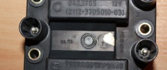
The letter designations are clearly visible on the device body. Because it is in it that a high-voltage pulse is generated, and there, in most cases, a break or rupture of the turns can occur.
It happens because of the following: The car was operating when the high-voltage wires were not working - approx.
And also the cause of the malfunction may be a soldering failure; this usually happens due to frequent vibration. Or moisture formed during washing or condensation. Testing with the engine running is done as follows.
The first contact of the tester is in socket D, the second is to ground. The multimeter switch position is 20 volts. If there is power, the tester shows 12 volts. The first contact is in socket C, the second is ground.
Switch on 20 Ohm ohmmeter. Normally it shows less than 1 ohm, that is, the mass is normal. The first contact is in socket B, the second is ground.
20 volt switch. The norm is not less than 0.3 volts. If this is the case, it means that a normal pulse is coming from the Hall sensor to position B. Contact A is checked in the same way as the previous one.
Chevrolet Niva ignition coil
If such a check shows the norm, you need to test the module. The old spark plugs are black with soot, but there is nothing criminal in appearance. We install new ones, pray and start them. Vzhiiiihh - it started, it doesn’t bother. I warmed up the engine a little, I try to drive - everything is cool, I’m on my way. I fly home quickly, joyful, it’s already 8 pm.
I think to myself - lucky that there are candles. It happens - it breaks through.
The next day in the morning I take my wife to work for 15 minutes there, I drive back and almost approach the house, I feel that the traction has disappeared, I press on the gas and the car slows down. A couple of seconds later the engine started up.
Damn, I think it’s good that I got there on my own. Google says - change the high-voltage wires, they also break through and in theory they should also be changed more often, and not ride on the same wires for years.
BB wires I take the bus and go to the nearest spare parts store. The choice is not great, there are no branded and cool Teslas and the like. This is especially true when operating in difficult conditions, when the engine operates at high speeds, while the travel speed is low and, as a result, the interior ventilation is insufficient.
On the Niva Chevrolet, the spark plugs are closely related to the previous device. And if they malfunction, all the same problems as described above are possible. Spark plugs fail especially often in winter. This is due to the fact that the car is not used so often and mainly for short trips. Due to the low ambient temperature, the candles do not warm up to the maximum temperature at which they self-clean from carbon deposits.
If problems occur, it is necessary to replace the spark plugs in a timely manner so that this does not affect the performance of other system components. Spark plugs for the Chevrolet Niva must be purchased specially for eight-valve injection engines.
Loading ..
When purchasing, you should pay attention to the gap between the electrodes. It should be no more than 1.5 mm
If this distance is greater, this will affect the duration of the candle.
Remove the engine screen. We remove the tips of the high-voltage wires from the ignition coil terminals. Having released the lock of the engine control system wiring harness block... ...disconnect the block from the coil connector. Using a 5mm hexagon, unscrew the four screws securing the coil to the bracket... ...and remove the coil. Install the ignition coil in reverse order. For the correct connection of the tips of high-voltage wires... ...the cylinder numbers are marked on the coil body next to its terminals.
The most common causes of malfunctions
One of the most common causes of breakdowns is the secondary winding . Because it is in it that a high-voltage pulse is generated, and there, in most cases, a break or rupture of the turns can occur. This happens because of the following:
- The car's operation took place when the high-voltage wires (high-voltage wires - approx.) were not working.
- The engine was equipped with spark plugs with inappropriate performance parameters.
And also the cause of the malfunction may be a soldering failure; this usually happens due to frequent vibration. Or moisture formed during washing or condensation.
More about breakdowns
Armored wires are marked with arrows
Read more: Matiz does not show gasoline
The same high-voltage pulse that appears on the secondary winding must be fully used, that is, if this does not happen (if the integrity of the wire is violated - approx.), then the pulse looks for the nearest “exit” and it finds it, as a rule, in that same secondary winding, which is much thinner than the cross-section of the wires themselves.
First signs of trouble
As a rule, two coils do not fail at once, therefore, it will still be possible to start the engine even with a partially faulty module. But an experienced car owner should immediately suspect a problem, and they are accompanied by the following:
- The engine is not able to easily gain “working” speed.
- The idle speed will "float".
- Engine tripping is possible.
- Jerking may occur during movement.
All of the above reasons can also be observed during other breakdowns, so it is necessary to diagnose it correctly, and for this you need to know how to check the ignition module with your own hands.
Please note that if such a malfunction occurs, it is highly undesirable to operate the vehicle, but if necessary, it is only possible to get to the place where it is repaired.
Procedure for checking the ignition module on a Chevrolet Niva
Before proceeding with dismantling the module, you need to make sure that the cause of unstable operation is not a simple lack of power contact. To do this, we “move” or turn on and off the connected block of wires several times. If such a procedure does not bring any results, then the functionality should be checked on a dismantled device.
The values on the multimeter are normal.
- When the element is removed, we prepare the multimeter for use and check the integrity and cleanliness of the sockets on the terminals (A, B, C, D - approx.).
- First of all, connect the red probe to contact – D, the second one to ground. We turn the multimeter into voltmeter mode - 20 volts, and if the socket is working, then the readings on the tester should be 12 volts.
- Next, go to contact – C, the second again to ground. We switch the multimeter to the ohmmeter mode and look at the readings of the device, and if it is less than 1 ohm, then the socket is normal.
- We check contacts A and B one by one, but in the same order. We connect the multimeter in voltmeter mode and if the readings do not exceed 0.3 volts, then the device can be considered fully working.
If any measurement shows results that do not meet the standards, then you should look for problems immediately in the coil circuit.
Transferring the ignition module
The ignition module has been moved higher
As already written above, for better operation of the ignition module, it is recommended to move it higher in the engine compartment.
How to check the ignition module on a Chevrolet Niva - check procedure
A multimeter will help you check the condition of the node . It is not necessary to use expensive instruments with high accuracy. The main thing is the presence of a digital display, then any measurements are simplified.
First you need to make sure that the wiring of the device remains intact. To do this , perform the following steps :
- The switch on the rear panel of the device is set to the 200 Ohm position.
- The connector is disconnected from the module and the high voltage wires are disposed of.
- The voltage is measured sequentially between the middle and extreme contacts of the terminal blocks.
- The device readings should be within 5 ohms. The heater, for example, works while maintaining other indicators.
The resistance of the secondary winding is checked in the next step . Here you need to move the switch to the 20 K position. The probes are connected to wires with the appropriate voltage. 5.4 Ohms is the standard reading for instruments in this situation. Otherwise, the connection cannot be properly organized.
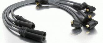
High voltage wires
Often, the main difficulty when repairing a carburetor VAZ 2109 is the reconnection of high-voltage wires that were previously disconnected from the distributor cover. It's also an ignition distributor.
The difficulty is that many people forget the connection procedure or simply do not know. But in practice, returning high-voltage wires is much easier than understanding the ignition module used on the injection VAZ 2109.
By following a few simple rules, you can easily return the wires to their rightful places.
- The ignition distributor cover is installed in its place, that is, on the distributor, only in a single position. Therefore, even if you wanted to, you won’t be able to confuse anything here. Otherwise the lid simply won't fit.
- There is an installation mark on the cover, which indicates the location of the wire socket from the first cylinder.
- The wires must be connected in the following sequence - 1, 3, 4, 2. Move counterclockwise when looking at the distributor cover from the side of the expansion tank.
General tips for connecting high-voltage wires.
Checking high-voltage wires. To check the wires, you will need a multimeter tester. Check the resistance of the wires - it should be no more than 20 KOhms (in practice, the longest wire of cylinder 1 has a resistance of up to 10 KOhms). If the wire resistance is more than 20 Kom, it must be replaced. Carefully inspect the wires for chafing on parts of the motor or other wires. In case of significant abrasion, replace the wire. In case of minor abrasion, it is possible to lay the wire so that it does not rub and fix it in this position.
Laying wires. Do not try to connect the wires in a bundle. Disassemble the wiring harnesses, release the wires from the plastic holders. Connect the high-voltage leads to the corresponding cylinder spark plugs. Lay the wires so that they do not rub against each other, engine parts, or hoses. Avoid sharp bends and tension on the wires. After connecting all the wires, secure them into the bundle with special comb holders included in the delivery kit.
The procedure for connecting I/O wires to a VAZ carburetor (2108, 2109, 21099)
The central wire from the distributor cover always goes to the ignition coil (bobbin).
The outlet of the distributor cover, which faces towards the front of the car, is connected to the first cylinder.
The outlet of the distributor cap, looking down, is connected to the third cylinder.
The outlet of the distributor cap, looking rearward, is connected to the fourth cylinder.
The outlet of the distributor cap, looking up, is connected to the second cylinder.
The procedure for connecting high-voltage wires to a VAZ Classic, Niva with a carburetor and distributor.
Central wire from the ignition coil (bobbin)
1 cylinder - above the vacuum corrector. Next, clockwise, the order is 1-3-4-2.
Injection VAZ produced before 2004 with an old-style ignition module (4-pin low-voltage connector)
Actually, on the module body it is already indicated which cylinder the pins correspond to - but we duplicated them in red in case the module gets completely dirty, and you might not be able to see it in the photo.
Injection VAZ produced after 2004 with a new ignition coil (3-pin low-voltage connector)
As with the old-style ignition modules, the new coils are also marked with pins corresponding to the cylinders. But the connection order is different from the order on the old-style ignition module. Be careful.
The process of replacing spark plugs
Required tools and materials:
- Spark plug head 16 mm;
- Spark plug head 21 mm;
- Candle tube;
- Clean rags.
Step-by-step instructions for replacing spark plugs in a Chevrolet Niva:
- Open the hood of the vehicle.
- Remove high voltage wiring. If necessary, take a photo or note the sequence of wire installation.
- Using a feeler gauge, check the gap between the spark plug electrodes.
- Check the gap of the new spark plugs.
- Screw the new parts back in with a torque of 31-39 Nm (the order in which the spark plugs are installed does not matter).
- Install the ignition wires in the same sequence as removal.
The procedure for replacing spark plugs on a Chevrolet Niva has been completed.
Ignition system harness
The ignition system ensures the formation of a spark in the cylinders according to the power strokes. In modern engines, wires are connected to sensors that monitor ignition, engine temperature and other parameters.
The ignition system harness 2123 (commonly called “braid”) is indicated in blue in the figure.
In the cabin, it connects to the controller (“brains”), the instrument panel, “ground” and sends wires to the rear harness. Exiting into the engine compartment, it is divided into two cores:
The largest one is directed to the radiator and along the way it is connected to the mass air flow sensor, crankshaft sensor, resistor, and electric fans.
Throwing over the power steering pump, wires extend from the core to the phase sensors, idle speed, throttle valve, detonation and injectors. This wiring controls the operation of the engine and ensures that it runs smoothly.
The second wire runs upward and is divided into two: wires go to the right to the plus and minus of the battery, and to the left to the adsorber, fuel pressure sensor and oxygen sensor.
On models with air conditioning, a branch goes from this harness to its fuse.
If at least one wire in the “braid” is short-circuited, there is a big risk that you will not be able to start the engine. The controller simply will not see information about its temperature, fuel supply to the injectors or throttle position.
In this case, it is better to immediately replace the entire harness than to contact a diagnostician, look for one wire and replace it if the result is questionable.
Check procedure
First you need to check all the contacts, both those suitable for the block and the high-voltage wires going to the spark plugs. To do this, simply disconnect the wires several times and reconnect them. If this does not bring positive results, you need to move on to the next steps.
To do this, they usually use a multimeter connected to contacts D and the second one connected to ground. The device itself is switched to 20 volt mode. In this case, the readings on it should be 12 volts. Then, using the same scheme, check contact C in ohmmeter mode. The reading should be less than 1 ohm.
Contacts A and B are checked in voltmeter mode. Their readings should not exceed 0.3 Volts. If at least one of these indicators is outside the normal range, you need to look for problems in the coil.
If you find damage to the soldering of the contacts, you can try to fix them yourself using a soldering iron. If the coil is damaged, the ignition module must be replaced.
Transferring a part
When the car is frequently used off-road, some car owners try to move the module as high as possible so that as little moisture gets on it as possible. Also, changing the location allows you to avoid overheating, which shortens the service life of the device. This is especially true when operating in difficult conditions, when the engine operates at high speeds, while the travel speed is low and, as a result, the interior ventilation is insufficient.
Possible causes of ignition module malfunction
Despite the high reliability and durability of the ignition module, during operation it can fail, like any other mechanism. Among all possible causes of breakdowns, in 9 out of 10 cases the following occur and are diagnosed:
- Use of inappropriate components in the ignition system. High-voltage wires are selected based on the parameters of the module, since excessively high or low voltage creates malfunctions or burns out contacts.
- Defective or damaged parts, poor quality assembly. Defective components break down faster and damage other components or elements of the system. Practice shows that the selection of high-quality components and their periodic diagnostics allow the module to remain operational for a long time.
How to check the Niva-Chevrolet ignition module
The ignition module (IM) of the Niva-Chevrolet car is highly reliable and, most often, provides sparking over many tens of thousands of kilometers. However, if it fails, it is difficult to diagnose due to the lack of obvious signs. The decent cost of a module does not always allow it to be replaced with a new one, which is called “blindly”. First you need to reliably verify that the old one is faulty. Read the article about how to check the ignition module of a Niva-Chevrolet.
The procedure for connecting high-voltage wires Niva Chevrolet
1.4. Chevrolet Niva engine ignition system (controller M7.9.7)
The ignition system (Fig. 1.4-01) uses a 4-lead ignition coil, which is a block of two 2-lead ignition coils. The ignition system has no moving parts and therefore requires no maintenance or adjustment, with the exception of the spark plugs.
Fig, 1.4-01. Ignition system: 1 - battery; 2 - main relay; 3 — ignition switch; 4 — spark plugs; 5 - ignition coil; 0 - controller; 7 — crankshaft position sensor; 8 - master disk
The current in the primary windings of the ignition coils is controlled by a controller that uses information about the engine operating mode received from the sensors of the engine control system. To switch the primary windings of the ignition coils, the controller uses two powerful transistor valves (Fig. 1.4-01).
The ignition system uses a spark distribution method called the “idle spark” method. The engine cylinders are combined in pairs 1-4 and 2-3, and sparking occurs simultaneously in two cylinders: in the cylinder in which the compression stroke ends (working spark), and in the cylinder in which the exhaust stroke occurs (idle spark).
Due to the constant direction of current in the primary and secondary windings, the sparking current of one spark plug always flows from the central electrode to the side electrode, and the second - from the side to the central one.
Chevrolet Niva engine ignition coil (controller M7.9.7)
The four-terminal ignition coil (Fig. 1.4-02 and 1.4-03) has the following three circuits (see Fig. 1.4-01):
Primary winding power circuit
The vehicle's electrical system voltage is supplied from the ignition switch to contact “15” of the ignition coil.
Circuit of the primary winding of the ignition coil of cylinders 1 and 4, contact “lb”
The controller switches to ground the circuit of the primary winding of the ignition coil, which supplies high voltage to the spark plugs of cylinders 1.4.
Circuit of the primary winding of the ignition coil of cylinders 2 and 3, contact “1a”
The controller switches to ground the circuit of the primary winding of the ignition coil, which supplies high voltage to the spark plugs of cylinders 2 and 3.
If any element of the 4-terminal ignition coil malfunctions, the entire assembly must be replaced.
Removing the ignition coil 1. Turn off the ignition.
2. Disconnect the wiring harness block from the ignition coil.
3. Disconnect the high-voltage wiring harness.
4. Remove the ignition coil by unscrewing the mounting bolts.
ATTENTION. Dismantling of high-voltage wires should only be done using the protective cap.
Installing the ignition coil
1. Install the ignition coil on the bracket on the engine and secure with bolts, tightening to a torque of 9.6. 15.4 N • m.
2. Connect the spark plug wires.
3. Connect the high-voltage wire harness to the coil leads and spark plugs.
Dampening detonation of a Chevrolet Niva engine (controller M7.9.7)
To prevent damage to internal engine parts due to prolonged detonation, the ECM adjusts the ignition timing.
To detect detonation, the system is equipped with a knock sensor, see section 1.1.
The controller analyzes the signal from this sensor and, when detonation is detected, which is characterized by an increase in the amplitude of engine vibrations in a certain frequency range, it adjusts the ignition timing using a special algorithm*
Adjustment of the ignition timing to dampen detonation is carried out individually for the cylinders, i.e. it is determined in which cylinder detonation occurs, and the ignition timing is reduced only for this cylinder*
In the event of a malfunction of the knock sensor, the corresponding malfunction code is entered into the controller’s memory and the malfunction indicator turns on* In addition, the controller, depending on the engine operating mode, sets a reduced ignition timing, which eliminates the occurrence of detonation.
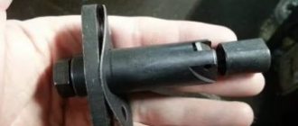
Design and principle of operation of the ignition module
Some old-school motorists call the modules double-spark coils, which makes sense. After all, the coil is the predecessor of the ignition module in the technical evolutionary chain. The module is a paired design consisting of two pairs of windings (primary and secondary) and a switch that alternately switches low-voltage current from one coil to another. In some models of double-spark coils, the commutator is structurally located outside the block .
The operation of the module is controlled from an electronic unit that collects and analyzes information from various working components of the engine. The block, unlike the classic coil, has 4 sockets for connecting high voltage wires going to the spark plugs. The pulse occurs in pairs, first at terminals 1 and 4, then 2 and 3. That is, each of the built-in coils is responsible for the operation of two cylinders. A spark occurs simultaneously, as a pair.
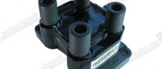
This is what one of the ignition module models looks like. The connector for connecting incoming wires is visible at the top.
At the input, the ignition module has a connector with four terminals. Usually most models have markings opposite them. Pulses from the Hall sensor alternately arrive at contacts A and B, serving as a signal to switch the commutator from one primary winding to another. C and D – ground and power supply (12 V), respectively.
Chevrolet Niva ignition module
After traveling through fords, another problem appeared: the engine was not running smoothly.
I changed the spark plugs and armor wires, but nothing helped. There was an assumption that the ignition module was to blame, and the contacts on it where the armor wires enter were all covered with blue powder. Clearly traces of water. My Chevrolet Niva is old, but it’s clear that the ignition module has never been changed. In the process of searching for a replacement, I looked through a lot of information. The ignition modules that came in cars from the factory lasted for a long time, more than 100 thousand km, but after replacing them, problems began. New modules traveled at most 10 thousand km, and sometimes they did not even travel 1000 km. The reason is that the Chevrolet Niva ignition module is sensitive to high temperatures, and it is mounted on the engine, where the temperature is always high. As a way out, people began to move it, for example, to the wing so that it would not get so hot. And this helped, but another problem appeared - low-quality spare parts. On the forum of Chevy Niv owners, somewhere I even came across a list of ignition modules from different manufacturers, where statistics were given on how long they last.
This problem is relevant not only for the Chevrolet Niva, but also for the VAZ 2112. Because before 2006, the Chevrolet Niva was equipped with an ignition module from the VAZ 2112, after 2006 from the VAZ 2111. The difference between them is that the ignition module from the VAZ 2112 is “smart” ”, i.e. It itself controls the process of supplying a spark, and from the VAZ 2111 this process is controlled by a computer and the module itself is essentially just ignition coils.
Naturally, I had a desire to change my module to a more reliable one from a VAZ 2111, but to do this, at a minimum, I would have to change the computer from Bosch 7.0 to Bosch 7.9.7, the latter has ignition control. This is all expensive and there is a cheaper solution from craftsmen.
On the Internet I came across a description of the “God’s Spark” system; it allows you to connect a reliable ignition module from a VAZ 2111 to a VAZ 2112 and Chevrolet Niva up to 2006. God's spark consists of an adapter cable and two modified controllers from the VAZ 2108. I didn’t quite understand why they needed to be modified, the only thing in the description was that with unfinished controllers there would be problems with ignition, which would be especially noticeable on turbocharged cars.
I ordered the “God's Spark” system before the New Year, but Russian Post took several weeks to deliver. And finally, after standing in line for a couple of hours, I got it. I bought an ignition module from a VAZ 2111 for it, a bracket for attaching it and a corner for attaching controllers.
Installation in the cold took several hours. I removed the old ignition module, its bracket and installed a new one. They are attached completely differently. Therefore, the new one, unlike the old one, is held on by one bolt, and not by three.
I secured the controllers to a corner, which I attached under the air filter mounting bolt. Having previously cleaned the metal, since the controllers require a good ground, just in case, I threw a separate ground wire to the battery. After that I connected everything and started checking.
Firstly, the car started up faster, and secondly, it began to pick up speed faster. Apparently the old ignition module was indeed faulty. By the way, I will carry it in the trunk, and I will attach the old bracket back, so if something happens to God’s spark, I can temporarily switch to it.
Ignition module for the Niva family.
The ignition module exists for injection fields in two modifications. Old sample and new sample. In the old version: a 4-pin connector and a large significant mass were installed on the fields of the first sample. New design: the connector has 3 contacts and low mass.
I came across the quality of this standard spare part completely by accident. A client comes for diagnostics and says that in the morning he turns the starter for 5-10 seconds until the engine “cages” for the first time. And at this time the injectors are pouring, it all flies out into the pipe.....and explodes in the muffler, turning around a large can. Having checked the spark as usual for ground, I saw its presence and calmed down. What I didn’t check: the performance of the boosts, replaced the spark plugs and wires, changed the gas station. And in the morning after a winter night we still use the starter to get the oil going. It turned out that the ignition module was to blame. He gave a spark in air to the candles, but its energy was so low that under the pressure in the cylinder, it could not ignite the mixture. On the forums, as usual, we delved into discussions about which modules to buy: Moscow, Stary Oskol or some other ones. I immediately ordered the Bosch module. I won’t delay the story for long....the next morning after installation, the engine started up with half a turn.
I confess that, to my shame, I do not know how the power of a spark is measured and if there are any instruments for this. To measure the power of the ignition module (and not at all for the Niva), I bought an insanely expensive “device” for 5 euros in the Finnish Biltema store, which is a transparent cylinder. This miracle is placed on one of the spark plug wires in an open circuit and in it you can clearly observe the power of the spark live. In the standard version, the gap between the poles is 1 cm, but even this distance may not be penetrated by the module. Subsequently, I made my own device, where the distance between the poles can be changed up to 2 cm and thereby look at the limit and at least the relative characteristics of the work.
Old style ignition module
The old-style module is produced by the fairly well-known German company Huco. Installed on cars with Bosch 7.0 ECU system. Mostly before 2008.
New ignition module
The ignition module is a new model, as I said above, from Bosch, although unlike the flow meter that is produced in Germany, this product is made in Brazil. But Bosch, he’s Bosch in Africa too))) What did the people of Nivovodsk notice after installing these ignition modules?
- The central contacts for the spark plug wires are made a little thicker than in the Russian version and the high-voltage wires fit very tightly.
- After installation, starting is easier after cold nights and the “reception” of the engine while driving is slightly improved.
- According to their adaptation, the results are as follows. It breaks through a gap of up to 2 cm with a spark. The domestic product takes the bar to only 1 cm, after which the engine already starts running on 3 cylinders.
I classified the ignition module in the “children’s tuning” section, although by and large, it is just an ordinary high-quality spare part with the characteristics that were included in the “standard” engine.
Frequently asked question: ignition modules are quite similar, how can you determine what is on the car?
Answer: Look at the module input connector. If there are 4 wires coming to it, you have the old version. If there are 3 wires - new.
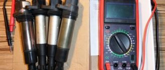
Methods for diagnosing device performance
The simplest method that will help determine the performance of the coil is to replace it with a similar working device. This is possible if there is somewhere to get it. Please note that the module must match the parameters of the device under test. If the engine with a working coil works as before the breakdown, the ignition module is definitely faulty.
The main testing method involves using a multimeter. It consists in determining the resistance of the secondary windings of the coils built into the ignition module. The method is simple and does not require additional skills. The device does not need to be removed for testing. The check is done with the engine turned off.
This is how you check the resistance of the secondary winding with a multimeter
- High-voltage wires are removed from the module sockets.
- The tester switch is set to the 20 kOhm position.
- The multimeter rods are placed in turn in the recesses of the corresponding contact pairs (1 and 4, 2 and 3).
- With an intact secondary winding, the performance in both cases is the same. Normally, the resistance should be about 5.4 kOhm (in some models the indicators differ, which needs to be clarified). If the resistance is much greater, then there is a winding break. The resistance is much lower - a breakdown. The coil is faulty and cannot be repaired.
Fines for crossing the stop line and speeding will no longer bother you!
Symptoms of a problem
As already mentioned, symptoms of a faulty ignition module are also typical for many other components of the car. There are almost no signs that directly indicate MH. This significantly complicates repairs. However, with experience, conclusions about a malfunction of the Chevrolet Niva ignition module can be drawn from the following symptoms.
- Two cylinders are not firing at once. This is the only sign that, although not always, indicates MH. The likelihood of this increases if cylinders 1 and 4 or cylinders 2 and 3 are not working at the same time.
- Idle speed “floats”.
- Diagnostics shows misfires in all cylinders.
- As the engine warms up, its power drops and interruptions appear.
- The CHECK ENGIN alarm comes on.
Also interesting: Chevrolet Niva camshaft sensor
It should be noted that a complete failure of the motor, in which the engine does not start at all, happens very rarely. Basically, this symptom of a malfunction of the Niva-Chevrolet ignition module indicates damage to the low-voltage part of the wiring.
Often the cause of problems with the Niva Chevrolet ignition module are breaks in the second winding, because it is this that generates the high voltage pulse. This mainly happens due to the fault of car owners:
- in case of untimely replacement of failed high-voltage wires
- installing spark plugs that do not match the car model.
- moisture ingress due to improper washing
Also, the cause of burnout may be delamination of the solder due to increased vibration during frequent use of the engine at high speeds or during frequent temperature exposure - engine overheating.
Also, if the integrity of the winding of high-voltage wires is violated, extinguishing occurs due to the secondary winding. The charge finds the nearest exit point and enters the place where the wires are thinnest, leading to their destruction.
Problems with the ignition module can be determined in advance, since two coils do not fail at the same time, so car owners will still have the engine start, but with some difficulties:
- it takes a long time to gain working momentum
- floating idle speed
- excessive engine vibration
- jerking while driving
But these problems may be associated not only with the ignition module, so before replacing it is recommended to check its condition
The principle of operation of the ignition module on a Chevrolet Niva
Ignition modules are structures equipped with both secondary and primary windings. Additionally, there is a commutator, inside which the current switches from one coil to another. The work is carried out from the computer or vehicle control unit. Analysis and collection of information is also performed using the specified blocks. This check gives an accurate result.
The ignition module has four sockets for connecting high-voltage wires. They then move on to the spark plugs.
Varieties
Over the entire period of production of these cars, manufacturers equipped them with two main groups of devices:
- MZ from a VAZ 2112 car. Mounted until 2006. It is equipped with a system responsible for controlling the sparking system.
- The module is from a VAZ 2111. It is controlled by signals from the ECU. In fact, this is an ordinary modern ignition coil.
The indicated modules are not classified as interchangeable parts. Their design is different, so it is impossible to replace one type with another. By appearance it is easy to determine which part is used in a particular case. The old Niva Chevrolet ignition module has increased dimensions and weight.
Module design
Converting low voltage signals to high voltage is the main purpose of any module. It is based on the process of spark formation inside the cylinders. The design of the module is similar to a pulse transformer. The signal from the electronic control unit is supplied to the input of the device. In this case, the voltage is removed from the output to 20-30 kW. This means that each wire works stably.
The module has a connector to connect the low-voltage part and four additional sockets. So-called armored wires are inserted into them.
High voltage is supplied to two cylinders at once. The formation of a spark takes up to 90% of the total energy of the device. The conductivity of the mixture is associated with high pressure, which is maintained on a constant basis. The module has only two independent coils.
Where is the ignition module located?
The part is fixed to the bottom of the cylinder block. For this reason, the ignition module is constantly exposed not only to corrosion, but also to high temperatures. The second factor for this system can be called the most critical. Therefore, owners often move the structure themselves to another place where the conditions are not so problematic.
The principle of operation of the ignition module on a Chevrolet Niva
The standard location of the ignition module under the hood raises questions.
The ignition module is a design with a primary and secondary pair of windings with a commutator, in which the current alternately switches from one coil to another. Its work is implemented from the ECU (control unit - approx.), and from it the analysis and collection of information from its work occurs.
The ignition module itself has four sockets for connecting high-voltage wires to them, which then go directly to the spark plugs.
Pulses in the module do not appear chaotically, but in pairs, that is, on terminals 1-4, and then 2-3, this is explained by the fact that each of the coils located inside is responsible for the actions of two cylinders, due to the pair occurrence of a spark.
Module design
The four terminals located on the module also have letter designations, so the connections marked A and B are suitable for pulses from the Hall sensor, which transfer the contacts from one to another, and contacts C and D are responsible for powering the ground, respectively.
The letter designations are clearly visible on the device body.
Ignition system in the field: self-replacement and ignition adjustment
As you know, engine performance is largely determined by the state of operation of the ignition system. Problems in the functioning of the latter can lead to the motor starting to work intermittently. From this material you can learn how to remove the ignition switch on a Niva with your own hands and adjust it, as well as what needs to be taken into account during this process.
Ignition system module for Niva
Before removing the ignition module on a VAZ 21213 carburetor or injector, it is necessary to diagnose the ignition coil, distributor and spark plugs. As practice shows, spark plugs are often the cause of incorrect operation of the internal combustion engine. If you are sure that the problem lies in the fault, then the installed device will need to be changed.
Also interesting: How to open the trunk door on a Chevrolet Niva - Auto repair school
How to replace the Niva ignition switch:
- First, the battery is disconnected and the steering column is removed.
- You need to mark the wires that are connected to the contact part of the VAZ ignition switch and disconnect them. Using a flat-head screwdriver, remove the bolt securing the system switch to the steering column bracket. You will also need to unscrew the screw that is located below, on the right side of the first one.
- Next, on Niva 21213 you need to turn the key to position 0, after which you need to use a screwdriver to slightly recess the device lock through the hole. The hole itself is located on the side of the steering column. Do not touch the exposed key.
- Before removing the ignition switch on the Niva, you need to pull it slightly towards you, after which the device is dismantled. In accordance with the connection diagram, the contact part of the device is replaced; to do this, you need to pry it off with a screwdriver and remove the retaining ring.
- Next, the contact part of the assembly is removed and changed if necessary. During installation, the rotating part must be turned counterclockwise using a screwdriver. Remove the key from the structure and install the contact part so that its wide protrusion can coincide with the wide cavity of the housing. Further assembly of the unit is carried out in reverse order.
1. Unscrew the 3Z mounting bolts. 2. Remove the assembly from its installation location. 3. Remove the contact part and replace it.
Description of the camshaft sensor on Niva Chevrolet
Where is it located: in engines with a gasoline power system, the DPRV is installed on the camshaft pulley. In an engine with a diesel power system, the control system is somewhat different. Where the upper and lower position of the piston in each cylinder is fixed.
On engines with a carburetor fuel system, the role of the DPRV is played by the distributor. The design of the injector is different, the system was parallelized, injection and ignition were done in pairs.
During systematic operation, the household equipment wears out and becomes unusable. The process of self-replacement is not at all difficult. The task is feasible for a car enthusiast without technical equipment maintenance skills.
To determine which cylinder is on stroke, the electronic engine control unit controls the position of the camshaft using DPRV (SMR)
Data from the sensor is extremely important for setting and dosing fuel, sparks in the combustion chamber, and injectors. The camshaft sensor directly affects fuel consumption, acceleration dynamics, and the amount of emissions in the exhaust gases.
In cars, including Niva Chevrolet, magnetic and Hall effect sensors are preinstalled. Both types are designed to read and transmit data to the electronic engine control unit.
The latter, based on the analysis of indicators, adjusts the fuel supply, ignition timing, and spark frequency.
- The magnetic controller produces its own alternating current. The design has two contacts;
- The Hall effect controller has one contact, powered from a third-party source.
Signs of DPRV malfunction:
- Unstable engine operation at idle speed;
- After stopping, the engine starts again;
- Increased fuel consumption;
- Power reduction;
- Passive acceleration dynamics;
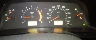
- On the dashboard there are system error indicators (see photo);
- The gearbox can be locked in one position until it comes to a complete stop and the ignition is turned off. Single or cyclic action;
- The car moves jerkily;
- The maximum speed of the car is limited to 65 – 85 km/h;
- Periodically the engine stalls;
- Misfires when turning on the ignition;
- Inability to restart the engine.
Frequent causes of premature wear of the controller:
- Natural factor due to long-term use;
- Mechanical damage to the controller housing;
- Open circuit;
- Short circuit of contacts;
- Sensor breakage due to impact, accident;
- Malfunctions of the electronic engine control unit.
| Name / catalog article | Price in rubles |
| Automega 150097810 | From 800 |
| JP group 1191400200 | From 800 |
| EPS 1953071 | From 800 |
| Delphi SS10814 | From 800 |
| Meyle 3148000038 | From 800 |
Also interesting: Review of standard Niva Chevrolet alarm system Preparatory stage:
- Key to "10";
- New controller;
- Rags;
- Phillips screwdriver;
- Additional lighting is optional.
Step by step guide:
- Open the hood;
- We release the metal clamp - the tie from the rubber pipe of the air duct. We extract it;
- At the top of the block we find the controller, remove the terminals, unscrew the bolt to “10”;
- We remove the sensor and replace it with a new one;
- We put on the terminals and install the air duct pipe.
The controller replacement is complete. We start the engine and check the serviceability of the equipment.
Checking the ignition module
Checking the ignition module for functionality is carried out in the following ways:
Replacing the ignition module with a known good one1. The easiest way is to connect a known working module. In this case, the devices must be completely identical, the high-voltage wires are in good condition, and the reliability of the contacts has been checked.
Checking the contacts on the ignition module2. Moving the module, which allows you to identify unreliable contacts. To do this, move the wire block and the module itself. If during exposure the engine reacts by changing its operation, then the cause of the problem lies in poor contact.
Measuring resistance at the terminals of the ignition module3. Resistance measurement. To do this, you will need a tester switched to ohmmeter mode. Measurements are carried out on the paired terminals of the module between cylinders 1 and 4, as well as cylinders 2 and 3. The resistance value should be the same and approach 5.4 kOhm.
Checking the ignition module using a tester4. Checking the voltage with a tester. One probe of the device is applied to contact A of the block, the second to ground. After turning on the ignition, take readings from the device. If the wire is in good condition, it will show a voltage of 12 V; if it is missing, check the fuse protecting the ignition module. Then check the continuity of the circuit with a 12 V test lamp. Apply one end of the wire to contact A and rotate the starter. If the lamp does not blink, the circuit is broken. The procedure is repeated in a similar way with other contacts.
Diagnostics of the ignition module using professional equipment5. Diagnostics at a service station by connecting a computer with special software to the ECU. Malfunctions are detected in the form of errors indicated by an alphanumeric code, after which a more in-depth diagnosis of the malfunction is carried out to make a decision - repair the ignition module or replace it. A similar check is carried out at a specialized service station using an oscilloscope.
Operating principles of the ignition module on a Niva Chevrolet
The ignition module in modern cars is responsible for generating high voltage pulses. Like all vehicle components, these devices are prone to failure and may require repair or replacement of the device. Before you begin these steps, you need to accurately diagnose the problem.
The ignition module structurally consists of two coils, in which the current is alternately redirected from one to the other. The electronic control unit system is responsible for the operation of the module. In addition, the ECU is responsible for collecting and analyzing data from its operation.
The pulse generated by the Niva Chevrolet ignition module comes out of four sockets, to each of which high-voltage wires are connected to transmit current to the spark plugs.
The pulses are generated in pairs, providing current simultaneously to the 1st and 4th terminals, then to the 2nd and 3rd. This is done specifically to match the specific cylinder operation.
Chevrolet Niva wiring diagram
The electrical equipment of the Chevrolet Niva is no different from its predecessors; wiring diagrams can be easily found on the Internet and repair work can be carried out. But for a person without experience, it is very difficult to understand them, especially if you do not know which harness contains the required wire and where it goes.
In this article we will talk specifically about the direction and connection of the power cores, and note their location in the pictures. This way you can easily find the wire indicated in the diagram and quickly resolder or extend it.
All electrical wiring of a car can be divided into three parts: engine compartment harnesses, instrument panels and doors (rear).