A collection of various options for Niva car electrical circuits. The presented color schemes are in good quality, high resolution and are suitable for the Niva VAZ-21213, Niva VAZ-21214 and Niva VAZ-2121 models. A newer version (2123) with the Chevrolet prefix is reviewed here. At the end of the page there is a link to free download of PDF manuals for this car, for independent repair and maintenance.
Electrical diagram of VAZ-2121
1 — side direction indicators; 2 — front lights; 3 — VAZ-2121 headlights; 4 — electric motors for headlight cleaners; 5 — sound signals; 6 — relay for turning on the headlight cleaners and washer; 7 — relay for turning on low beam headlights; 8 — relay for turning on the high beam headlights; 9 — electric motor for windshield washer; 10 — sensor of insufficient brake fluid level; 11 — plug socket of a portable lamp; 12 — oil pressure warning lamp sensor; 13 — oil pressure indicator sensor; 14 — coolant temperature indicator sensor; 15 — ignition distributor; 16 — spark plugs; 17 — electric motor of the windshield wiper; 18 — ignition coil; 19 - generator; 20 — carburetor shut-off valve; 21 — VAZ-2121 starter; 22 — headlight washer motor; 23 - voltage regulator; 24 — battery charge warning lamp relay; 25 - battery; 26 — windshield wiper relay; 27 — additional fuse block; 28 — main fuse block; 29 — parking brake warning lamp switch; 30 - switch for differential lock warning lamp; 31 — reverse light switch; 32 — switch for the carburetor air damper warning lamp; 33 — brake light switch; 34 — heater electric motor; 35 — relay-interrupter for direction indicators and hazard warning lights; 36 — additional resistor of the heater electric motor; 37 — instrument lighting switch; 38 — headlight switch; 39 — direction indicator switch; 40 — sound signal switch; 41 — wiper switch; 42 — windshield washer switch; 43 — ignition switch; 44 — external lighting switch; 45 — heater switch; 46 — switch for headlight cleaners and washer; 47 — cigarette lighter; 41 — alarm switch; 49 — lamp switches located in the door pillars; 50 — oil pressure gauge with insufficient pressure warning lamp; 51 — fuel level indicator with fuel reserve warning lamp; 52 — tachometer; 53 — parking brake warning lamp; 54 - battery charge indicator lamp; 55 — control lamp for the carburetor air damper; 56 — speedometer; 57 — control lamp for external lighting; 58 — turn signal indicator lamp; 59 — control lamp for high beam headlights; 60 — relay-interrupter for the parking brake warning lamp; 61 — brake fluid level warning lamp; 62 — differential lock warning lamp; 63 — coolant temperature indicator; 64 — lampshades; 65 — sensor for level indicator and fuel reserve; 66 — rear lights; 67 — license plate lights.
Instrument panel pinout Niva 21213 injector
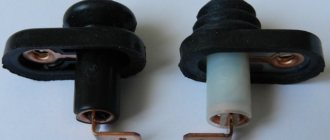
Vladimir instrument cluster
Installed on all Niva family cars from 1998 to the present. Difference from the Hungarian one: the scales of all instruments are printed on one black plate; in the Hungarian ones, each instrument has a separate black plate with a scale.
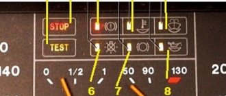
Captions for the instrument cluster wiring diagram
1 – electronic tachometer; 2 – coolant temperature indicator; 3 – fuel level indicator, - 4 – instrument lighting lamps; 5 – warning lamp for engine overheating (CHECK ENGINE); 6 – indicator lamp for heated rear window; 7 – indicator lamp for rear fog lights; 8 – control lamp for high beam headlights; 9 – indicator lamp for external lighting; 10 – indicator lamp for direction indicators; 11 – indicator lamp for battery discharge; 12 – resistor 50 Ohm, 5 W; 13 – warning lamp for malfunction of service brakes; 14 – warning lamp for emergency oil pressure; 15 – differential lock warning lamp; 16 – fuel reserve warning lamp; 17 – warning lamp for unfastened seat belts; 18 – parking brake warning lamp.
Diagram of the VAZ-21213 car
Electrical diagram of VAZ-21213 (Carburetor). Years of manufacture: 1993-2009. The diagram shows a relay for rear fog lights, used since 2000; before that they were turned on directly from a latching switch.
1 — front lights; 2 – side direction indicators; 3 — electric motor for windshield washer; 4 — headlight washer motor*; 5 - switch; 6 – battery; 7 - starter; 8 – generator; 9 — VAZ-21213 headlights; 10 – gearmotors for headlight cleaners*; 11 – sound signal; 12 – spark plugs; 13 — carburetor limit switch; 14 — carburetor solenoid valve; 15 — ignition coil; 16 — windshield wiper gearmotor; 17 – carburetor solenoid valve control unit; 18 — ignition distributor sensor; 19 – coolant temperature indicator sensor; 20 – oil pressure warning lamp sensor; 21 – plug socket for a portable lamp**; 22 – brake fluid level warning lamp sensor; 23 – windshield wiper relay; 24 – relay for turning on the rear fog light***; 25 – relay for turning on the heated rear window; 26 – relay for turning on headlight cleaners and washer*; 27 – relay for turning on low beam headlights; 28 — relay for turning on the high beam headlights; 29 — ignition relay VAZ-21213; 30 – starter activation relay; 31 — relay-breaker for alarm and direction indicators; 32 — heater electric motor; 33 – additional resistor of the heater electric motor; 34 – backlight lamps for heater control levers; 35 – external lighting switch; 36 – main fuse block; 37 – additional fuse block; 38 – reverse light switch; 39 – brake light switch; 40 – instrument lighting regulator; 41 – ignition switch; 42 – three-lever switch; 43 – alarm switch; 44 – tailgate glass cleaner and washer switch*; 45 – heater motor switch; 46 – switch for heating the rear door glass; 47 – rear fog light switch; 48 – lamp switches located in the door pillars; 49 – interior lamps; 50 – Niva cigarette lighter; 51 – switch for the warning lamp for closing the carburetor air damper; 52 – control lamp for covering the carburetor air damper; 53 – switch for the differential lock warning lamp; 54 – parking brake warning lamp switch; 55 – sensor for level indicator and fuel reserve; 56 – instrument cluster; 57 – tailgate glass washer motor; 58 – rear lights; 59 – block for connecting additional brake lights; 60 – blocks for connecting side marker indicators; 61 – pads for connecting to the heated glass element of the tailgate; 62 – license plate lights; 63 – rear door glass wiper motor.
The order of conditional numbering of plugs in blocks:
a – windshield wipers, headlights and tailgate glass, windshield wiper relay breaker; b — ignition distributor sensor; c – relay-interrupter for alarm and direction indicators; d — switch VAZ-21213; d — three-lever switch; e — alarm switch; g – relay for turning on the rear fog light; h — rear lights (numbering of terminals in order from top to bottom); and – instrument clusters.
In the instrument panel wiring harness, the second ends of the white wires are brought together to one point, which is connected to the instrument lighting control. The second ends of the black wires are also brought together to a point connected to ground. The second ends of the yellow wires with a blue stripe are brought together to a point connected to terminal “A” of the main fuse block. And the second ends of the orange wires are also brought together to a point connected to terminal “B” of the main fuse block.
Electrical wiring Niva 21213: features of unification
Did you like the article? Follow our channel for new ideas of useful car tips. Subscribe to us in Yandex.Zen. Subscribe.
The VAZ 21213 is the successor to the VAZ 2121 Niva, and was launched into production in 1994. The addition of a “C” in the index marked a new era of the off-road version of the car, although most of the parts were used from the entire model range of the Togliatti Automobile Plant.
In particular, the car received:
- Power unit from VAZ 2106 with volume increased to 1.7 liters;
- Two-chamber Solex carburetor;
- Contactless ignition system on a microcontroller;
- 5-speed gearbox (modified from VAZ 2121).
For reference: cars of the Niva family have become popular in many countries. A promotional video about their unique off-road qualities, like the cars themselves, can be found in Japan, Brazil, Chile and even Australia.
Motor control circuit
Connection diagram of the VAZ-21214 engine management system with central fuel injection under US-83 toxicity standards with controller 21214-1411010 (EFI-4 type) on VAZ-21214 vehicles:
1 - control lamp “CHECK ENGINE”; 2 — instrument cluster (fragments); 3 — electric fans of the engine cooling system*; 4 — electric heater of the intake pipe; 5 — air temperature sensor; 6 — absolute pressure sensor; 7 — coolant temperature sensor; 8 — block connected to the throttle position sensor; 9 — central fuel injection unit; 10 — block connected to the idle speed regulator; 11 — block connected to the nozzle; 12 — diagnostic block; 13 - controller; 14 — knock sensor; 15 — speed sensor; 16 — oxygen concentration sensor; 17 - adsorber; 18 — battery; 19 - main relay; 20 — fuse block of the engine control system; 21 — relay for turning on the electric fuel pump; 22 — relay for turning on the electric fan*; 23 — relay for turning on the electric heater of the inlet pipe; 24 — electric heater protection fuse; 25 — starter activation relay; 26 — ignition relay; 27 — main car fuse box (fragment); 28 — spark plugs VAZ-21214; 29 — tachometer; 30 — electric fuel pump with fuel level sensor; 31 — ignition module; 32 — crankshaft position sensor; 33 - courtesy light switch, located on the driver's door pillar; 34 — control unit of the automobile anti-theft system**; 35 — status indicator of the car anti-theft system**; A - wire going to plug “50” of the ignition switch; B - wire going to plug “15” of the ignition switch; B - wire going to terminal “30” of the generator; G - rear wiring harness wires connected to the fuel level indicator; D - rear wiring harness wire connected to switch 33.
Useful: Connection diagram for generator in VAZ cars
Connection diagram of the VAZ-21214 engine management system with distributed fuel injection under Euro-2 emission standards with controller 2123-1411020-10 (MP 7.0 type) on VAZ-21214 vehicles:
1 — warning lamp of the engine management system; 2 — instrument cluster (fragments); 3 — electric fans of the engine cooling system; 4 — courtesy light switch, located on the driver’s door pillar; 5 — status indicator of the car anti-theft system; 6 — control unit of the automobile anti-theft system; 7-coolant temperature sensor; 8 — air flow sensor; 9 — throttle assembly; 10 — block connected to the throttle position sensor; 11 — block connected to the idle speed regulator; 12 - controller; 13 — oxygen concentration sensor; 14 — knock sensor; 15 — crankshaft position sensor; 16 — speed sensor; 17 - adsorber; 18 — battery; 19 - main relay; 20 — diagnostic block; 21 — fuse block of the engine control system; 22 — relay for turning on the electric fuel pump; 23 — relay for turning on electric fans; 24 — main car fuse box (fragment); 25 — block connected to the additional wiring harness*; 26 — ignition module; 27 - tachometer VAZ-21214; 28 — electric fuel pump with fuel level sensor; 29 — nozzles; 30 — spark plugs; A - rear wiring harness wire connected to switch 4; B - wires connected to plug “1” of fuse block 24 (one wire goes to plug “15” of the ignition switch, and the other to plug “85” of the ignition relay); B - rear wiring harness wires connected to the fuel level indicator.
The order of conditional numbering of plugs in the blocks: a - controller; b — control unit of the automobile anti-theft system; in - air flow sensor; g — speed sensor; d — indicator of the state of the automobile anti-theft system; e — electric fuel pump and oxygen concentration sensor; g - throttle pipe; h — ignition module.
Replacing Chevy Niva engine components
So, the first method is engine tuning, which involves replacing some components. First of all, this concerns the cylinder-piston group (CPG) and the crank mechanism (CPM), which requires boring of the liners. All this allows you to increase the working volume and, as a result, the power indicator.
First of all, boring is carried out, allowing the inner diameter of the liners to be increased. After this, a selection of pistons and piston rings of appropriate size is made. In addition, the engine is equipped with a crankshaft with elongated arms, as well as shortened connecting rods. Thanks to this, it is possible to increase the piston stroke. All this leads to an increase in volume from 1.7 liters, which the factory Chevy engine has, to 1.9 liters.
But replacing only the crankshaft and CPG motor is not enough. An increase in volume entails the need to increase the combustible mixture supplied to the cylinders and to better ventilate them. For this purpose, the cylinder head (cylinder head) is also subjected to tuning. First of all, the intake and exhaust windows are bored, and the valves are replaced with larger ones. At the same time, the valve seats are bored out and replaced.
Boring of inlet and outlet windows
Additionally, you can completely change the exhaust system by increasing the diameter of the exhaust pipes, and also replace the catalytic converter (catalyst) with a flame arrester.
Note that design changes to the engine will entail the need to reconfigure the operation of the fuel supply system, since with standard configurations and an increased volume, there will not be enough fuel supplied to the cylinders. That is, it will still be necessary to carry out chip tuning.
All this tuning, associated with changes in geometry, allows you to increase engine power by 15% of the nominal. But it is worth noting that an increase in volume will also entail an increase in fuel consumption.
Relays and fuses Niva
The main fuse box is located in the passenger compartment under the instrument panel, to the left of the steering wheel. To access the blocks, pull the latch located on top of the blocks and remove the cover.
- engine control system fuse box;
- windshield wiper relay;
- fuse blocks VAZ-2121;
- engine control system relay block.
Main fuse box
| Designation and current, A | Protected Circuits |
| F1 (16) | Heater Blower Motor Switch, Tailgate Defroster Switch, Tailgate Wiper Motor, Tailgate Wiper/Washer Switch (Windshield Washer Pump) |
| F2 (8) | Steering column switch, windshield wiper motor, hazard warning switch, breaker relay (in turn signal mode), reverse light switch, instrument cluster (coolant temperature gauge, fuel level gauge, tachometer, indicator lamps: turn indicators, differential locks, parking brake, emergency condition of the service brake system, insufficient oil pressure, fuel reserve, battery charge) |
| F3 (8) | Left headlight (high beam), high beam indicator lamp |
| F4 (8) | Right headlight (high beam) |
| F5 (8) | Left headlight (low beam) |
| F6 (8) | Right headlight (low beam) |
| F7 (8) | Side light lamps in the left front and left rear lights, license plate lights, side light indicator lamp |
| F8 (8) | Side light lamps in the right front and right rear lamps, backlight lamps for the instrument cluster, cigarette lighter, switches, heating and ventilation control unit |
| F9 (16) | Hazard switch, breaker relay (in hazard mode), heated tailgate glass relay contacts |
| F10 (16) | Sound signal, interior lamps, brake lamps in the rear lights |
| F11 (8) | Reserve |
| F12 (8) | Reserve |
| F13 (8) | Fog light relay contacts in rear lights |
| F14 (16) | Cigarette lighter fuse |
| F15 (16) | Reserve |
| F16 (8) | Reserve |
Engine control system fuse box
| Designation and current, A | Protected Circuits |
| F1 (30) | Right electric fan relay contacts |
| F2(30) | Left electric fan relay contacts |
| F3 (15) | Relay windings of the right and left electric fans, controller, injectors, ignition coil |
| F4 (15) | Heating elements for control and diagnostic oxygen concentration sensors, phase sensor, mass air flow sensor, canister purge valve |
On the left under the instrument panel, on the body, there is a block of four fuses for the engine management system and a diagnostic connector. To access the block, unscrew two self-tapping screws and remove the casing.
Engine control relay
Below the main fuse box are the engine management system relays.
- ignition relay;
- Niva main relay;
- right electric fan relay;
- left electric fan relay;
- fuel pump relay;
- fuel pump fuse (F5, 15 A).
Relay box under the dashboard
Under the instrument panel, just above the gas pedal, there is a block with four relays.
- Niva rear fog light relay;
- relay for turning on the heated glass of the tailgate;
- low beam headlight relay;
- high beam headlight relay.
Above this block, behind the instrument cluster, there is a turn signal and hazard warning relay.
Blocks for LADA 4X4 2021
The relay and fuse diagram may differ depending on the configuration and production date of the vehicle. Current diagrams of the mounting block are presented in the operating manual as of the date of manufacture of the vehicle.
The fuses are grouped in two fuse blocks located on the left under the instrument panel. The fuse ratings and the circuits they protect are shown in the table.
The fuses for the VAZ 2131 injection system are located in a separate block on the left side under the instrument panel.
The electric motors of VAZ-2121 gearmotors (windshield wipers, tailgate glass, headlights - if installed) are protected by automatic reusable bimetallic fuses. The power supply circuit of the injection system is protected by a fuse-link made of wire with a conductor of reduced cross-section (1 mm2). The battery charging, ignition, engine starting, and “generator – ignition switch – fuse box” circuits are not protected. Powerful consumers (starter, headlights, electric motors Niva 2131 cooling system fans, electric fuel pump, etc.) are connected via a relay.
Instrument cluster diagram, instrument cluster troubleshooting
Note Regardless of the modification of the instrument cluster (until 2009), the algorithm for troubleshooting and troubleshooting is approximately the same. The electronic instrument cluster (after 2009) cannot be repaired , with the exception of replacing indicator lamps and instrument lighting. The components of the instrument cluster are not supplied as spare parts, therefore, in the event of failure of one of the instruments, the combination must be replaced as an assembly.
All vehicle control devices are combined into an instrument cluster. It includes: a speedometer with a trip meter, a coolant temperature indicator, a fuel level indicator, a tachometer, and warning lights.
Since 2009, Lada Niva 4×4 cars have been equipped with an electronic instrument cluster borrowed from the Samara-2 family. It includes an electronic speedometer and tachometer, a liquid crystal indicator of the total and daily mileage counter (odometer), a liquid crystal display of the clock and ambient temperature, a coolant temperature indicator, a fuel level indicator, twelve signaling devices and six backlight lamps. The operation of the devices is controlled by an electronic module, which receives signals from sensors. Temperature and fuel level indicators are of electromagnetic type. The tachometer and speedometer needles are driven by stepper electric motors.
Connection diagram of the instrument panel wiring harness (after 2009)
Connection diagram of the instrument cluster produced since 1996. (inside view)
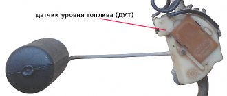
The coolant temperature gauge works in conjunction with a sensor screwed into the cylinder head. The sensor contains a thermistor (a resistor that changes its resistance depending on temperature).
Data for checking the coolant temperature gauge sensor
Source