Lada Priora cars are equipped with an ignition lock (switch) version 11180-3704010 with a built-in anti-theft lock, coil connection with the immobilizer and a function to prevent the starter from restarting without turning off the ignition.
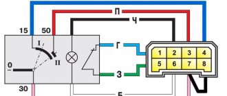
The electrical diagram of the Lada Priora ignition switch given below allows you to more accurately understand the causes of possible malfunctions of the switch and to monitor its performance, first of all, check the reliability of contact closure in all key positions, the ease of closing and opening the anti-theft device, as well as the presence of a stable connection with the standard immobilizer .
The main voltage to the lock is supplied through contact “30” directly from the car’s power supply sources (battery or generator), and the unloading of the contacts most often involved in operation is carried out through the participation of relay K4, located in the mounting block.
Removing the ignition switch (switch) of VAZ 2170 (2171, 2172)
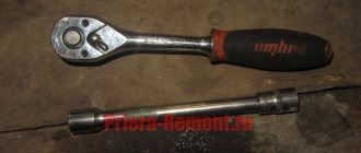
To perform this technological operation, you must have a flat and Phillips screwdriver on hand, as well as a chisel and a hammer.
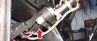
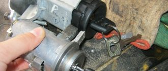
Removing the ignition switch of a Lada Priora begins with disconnecting the power wire from the negative terminal of the battery, thereby protecting ourselves from possible troubles associated with unintentional short circuits. Next, by unscrewing seven bolts, the protective cover of the steering column is removed, after which access to the ignition switch mount (four bolts with cut-off heads) is opened.
The easiest way to unscrew such screws is to use a hammer and chisel; as a rule, such a tool is needed only to “break” the screws and then they can be easily unscrewed simply by hand. If you don't have a chisel, a drill can help you remove these screws.
At the final stage of dismantling the lock, the immobilizer coil is removed from it and the connecting blocks are disconnected, after which it is easy to pull it out of the mounting socket.
Preventative and repair work
If it is necessary to perform preventive and repair operations, further disassembly of the switch is performed, for which three screws are unscrewed with a Phillips screwdriver and the mounting bracket is disconnected from the lock.
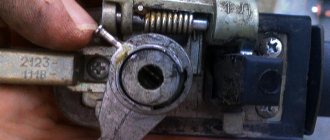
Please note that the removal of the locking device drive is prevented by a special cylinder stop. To successfully carry out this procedure, you do not need to completely remove the cylinder - you just need to pull out the locking ball, which is pressed by the spring. By the way, it is this spring that often causes the lock to jam, and if it fails, it can be replaced with a similar spring from the VAZ 2108 lock of the latest modifications.
To gain access to the contact block, it is necessary to remove the switch body, and this procedure is performed by pressing the side plastic latches. On the terminal block, it is necessary to check the condition of the contacts and then remove all detected damage. If traces of scorch are found, it is removed using fine-grain sandpaper. In the event of severe, irreparable melting of the contacts, the contact group is replaced as an assembly. In this case, you will have to spend some time and solder three wires.
One of the most critical in terms of malfunctions is the terminal block. Its disassembly is also not particularly difficult - you just need to bend the latch and fold back the protective cover. Before pulling the wires out of the block, do not forget to first write down their original location. All wires and terminals are inspected for mechanical damage and oxidation that could lead to malfunctions of the lock.
The lock is assembled in the reverse order. When installing the lock, do not forget to recess the rod of the anti-theft device (otherwise installation will be impossible). To do this, you need to insert the key into the lock cylinder and move it from the neutral position “0” to any other position.
In case of a complete replacement of the lock, you should additionally replace the code elements located in the heads of the new keys with the code elements removed from the key heads of the removed ignition lock. In this case, the immobilizer training procedure will not be required.
Click to enlarge the diagram
A – to the (+) “plus” terminal of the battery B1 and B2 – grounding points of the ignition system wiring harness C1 – grounding point of the wiring harness from the ignition coils
1. – M7.9.7 controller 2. – connector for connecting the ignition system harness to the instrument panel harness connector 3. – block with the main 30A fuse 4. – speed sensor 5. – electric idle speed control 6. – air flow sensor 7. – instrument sensor engine coolant temperature readings 8. – engine coolant temperature sensor 9. – throttle position sensor 10. – oil pressure warning lamp sensor 11. – rough road sensor 12. – electric fuel pump relay 13. – fuse (15 A) in the circuit electric fuel pump power supply 14. – ignition relay 15. – fuse (15 A) power supply to the ignition relay 16. – fuse (7.5 A) in the power supply circuit of the vehicle controller 17. – crankshaft position detection sensor 18. – oxygen flow sensor 19. – phase sensor 20. – knock detection sensor 21. – solenoid valve for canister purge 22. – diagnostic oxygen sensor 23. – spark plug coils 24. – spark plugs 25. – injectors 26. 26-27 – connector blocks connecting the ignition coil wiring harnesses to the harness ignition system wires 27. 28-29 – blocks connecting the ignition system wire harnesses with the injector control wire harness
On x, a Lada Priora ignition switch (lock) type 11180-3704010 with an anti-theft locking device is used, blocking the restart of the VAZ 2172 starter without first turning off the ignition and a communication coil of the ignition key transponder with the automobile anti-theft system.
- Ignition switch connection diagram (with key inserted)
At the ignition switch, check the correct closure of the contacts at various key positions (Table 10.4), the operation of the anti-theft device and the presence of communication with the automobile anti-theft system. The voltage from the battery and the Lada Priora generator is supplied to terminal “30”.
To unload the contacts of the ignition switch, relay K4 is installed in the mounting block.
The locking rod of the anti-theft device extends if you set the key to position “0” (off) and remove the VAZ 2171 from the lock. The locking rod is retracted after turning the key from position “0” (off) to position “I” (ignition). The key can only be removed from the lock in position “0”.
The locking device for reactivating the VAZ 2170 starter should not allow the key to be turned again from position “I” (ignition) to position “II” (starter). Turning the ignition key to this position should only be possible after returning the key to the “0” (off) position.
- Switched circuits at different key positions
On Lada Priora cars, an ignition switch (lock) type 11180-3704010 is used with an anti-theft locking device, a blocking for re-starting the starter without first turning off the ignition and a communication coil for the ignition key transponder with the car's anti-theft system.
The ignition switch is checked for correct closure of the contacts at different key positions, operation of the anti-theft device and the presence of communication with the car anti-theft system.
The voltage from the battery and generator is supplied to contact “30” (Fig. 1).
Rice. 1. Connection diagram of the ignition switch (with the key inserted)
To unload the contacts of the ignition switch, a “K4” relay is installed in the mounting block.
The locking rod of the anti-theft device extends if you set the key to position “0” (off) and remove it from the lock.
The locking rod is recessed after turning the key from position “0” (off) to position “I” (ignition).
The key can only be removed from the lock in position “0”.
The starter restart locking device must not allow the key to be turned again from position “I” (ignition) to position “II” (starter).
Turning the ignition key to this position should only be possible after returning the key to the “0” (off) position.
Features of the ignition switch on Priora
The Priora ignition switch is a unit equipped with an anti-theft device and a restart blocker for the starter mechanism. As can be seen from the diagram, the voltage from the battery is supplied to output 30 of the VAZ ignition device. To ensure protection of the unit circuit, relay K4 is installed in the fuse block. When the ignition key on a Priora is set to position 0, the locking rod of the anti-theft mechanism extends. The key can only be removed in this position.
Different circuits are activated in different key positions:
- I. In accordance with the connection diagram of the connection wires, in this position the operation of the motor control system, the excitation circuit of the generator unit, optics, and alarm are activated. The instrument panel, windshield cleaning system, and power windows are also included, if included in the package.
- II. In this position, all components activated in position I work, as well as the starter device (video author: Alexey Wolf).
What is the device?
The ignition switch is a special device that supplies direct current to the starter traction relay. Such impulses come from the battery and are activated when the lock is turned on. Without the correct operation of the device, the car will not function fully.
Design Features
The mechanism includes two main parts. The ignition key is placed in the lock cylinder, which puts the car into operating mode and activates the lock itself. The second part is the contact group. It closes in a certain sequence, depending on the position of the key in the cylinder.
Why the system might break down
The need to replace the lock may arise for a number of the following reasons:
- wear and tear of individual parts. Burnouts or oxidation of the system drives are common;
- incorrect contacts. Violation of such circuits leads to combustion, oxidation and lack of working abilities;
- cylinder wear. The breakdown is manifested by difficulties when using the key;
- Lost car key. A trivial but compelling reason for replacement.
Possible malfunctions of the protection system and ways to eliminate them
If the ignition switch fails on a VAZ 2170, many motorists may confuse this problem with a breakdown of the ignition coil or, for example, the ignition module. But as for the 3Z specifically, its repair or replacement is carried out only if the key is not moved to position I or the steering wheel is not blocked after the key is removed. The key must always return to position I after starting the engine. If this does not happen, then you can either repair or replace the ignition switch.
Troubleshooting
The ignition switch on a Priora often fails due to improper use. The first step before replacing the device is to disconnect the battery. To do this, remove the terminal. Also remember to remove the steering cover and disconnect the electrical connectors.
The Priora ignition switch is bolted to the steering rack. You won't be able to unscrew them with a screwdriver or keys. You need to use a hammer or chisel. Otherwise, use an electric drill, which can remove the bolts.
Replacing the ignition switch on a Priora includes checking the voltage of each contact. This process prevents unwanted problems with the new lock. In order not to confuse the connection of the contact group, their “natural” arrangement is first recorded. This simplifies the work with replacement and provides you with a hint when completing the assembly of the mechanism.
If the Lada Priora ignition switch is not replaced, then problems may arise with its components. Replacing a contact group involves the following process:
- The casing is removed and the lock is pulled out.
- The correct pin connection sequence for reconnection is recorded.
- According to the recorded connection principle, a new contact group is distributed.
- Place the lock in its original position, covering the steering wheel with the removed cover.
Repair instructions
The location of the 3Z is known to everyone - this unit is located directly under the steering wheel. To properly replace or repair a device, you must follow the instructions:
- First, disconnect the battery and remove the plastic steering column cover, which is secured with bolts.
- Next, press out the fastening and disconnect the connector with the 33 wiring from the control panel wiring block. When unplugging, be careful not to damage the plug.
- Having done this, you will also need to disconnect the plug with the 3Z wires from the connector with the wiring of the immobilizer control system. Using a hammer and chisel or a drill, you need to remove the four breakaway screws and remove the assembly from the steering column. You can't just unscrew these bolts. VAZ engineers decided to use this method of installing the protection in order to protect car owners from possible thefts. This method of fastening, as you can guess, makes it very difficult to dismantle the protection, so at this stage you will have to tinker. In any case, the bolts can be dismantled or drilled out, but instead you will have to purchase new ones in advance.
- After completing these steps, you can bend the connector mount with wiring from the 3Z. The terminals with wires are removed from this connector. Next, you need to compress the latches again and dismantle the plastic cover of the device itself. If you plan to simply change the node, then this can be done at this stage. We suggest that you familiarize yourself with more detailed information on repairs - it is quite possible that simple steps will restore the unit’s functionality and save money.
- So, if you decide to repair the mechanism, then at this stage you need to press out two more plastic clips and remove the contact group from the cover.
- Next, it is necessary to carry out a thorough visual diagnosis of the contacts. If you notice that the contacts have oxidized or burnt, you can restore their functionality by cleaning them using fine-grained sandpaper. Get rid of oxidation and plaque, but do not go too hard so that the contacts do not wear off. If the damage to the contacts is too severe, then cleaning will not solve the problem - you will only need to change either the contactor itself or only the contact group.
- If everything worked out with the contacts, then you can assemble and install the protection. During assembly, pay attention to the position of the terminals with the wiring in the connector; under no circumstances should they be mixed up.
- After completing these steps, install the locking device back into place, while pre-sinking the locking rod of the anti-theft unit. To do this correctly, install the key in the 3Z and turn it to any position, the main thing is that it is not in the “0” position. If the key is replaced, then the transponders must also be changed - these are special electronic code components on the head of the key. If you do not do this, then you will also have to carry out the training procedure, as well as change the lock cylinder on the trunk and doors, and this is a rather labor-intensive process. Otherwise, you will have to use the old key to open the doors and trunk and the new one to start the engine. Agree, this is completely inconvenient, but this is only relevant for those car owners who have changed their license plate.
We fix the most common problems
Then we begin to correct problems in the wiring system. Most often, problems in the ignition system are associated precisely with oxidation or chafing of the wire group.
Carefully pry (using a flat-head screwdriver) the plastic latches on the cover of the wire block and open it
It is important to remember, or better yet, note the location of the wires there, so as not to get confused during reassembly. If you are not a pro, then the easiest way is to record the location of the wires using a camera on your mobile phone.
We sequentially unbend the metal “antennae” and take out the wiring. During this operation, we will be able to clean the contacts and check their integrity.
We go directly to the ignition mechanism, remove the wires located on the ignition system housing. To do this, use a screwdriver to press out the latches (they are plastic, so disassembling them is not difficult, but this must be done carefully) and remove the wiring from the housing.
The housing contains a contact group, which starts the vehicle systems
It is important to check its condition and possible problems
The part we have to pay special attention to is the moving contact. It needs to be disassembled and checked
To do this, we separate it from the stator contact group and disassemble it. Disassembly is carried out by simply pressing on this mechanism and turning it counterclockwise. As a result, the contact spring is separated and checked, and it is also possible to access the check of the car's anti-theft system.
Cleaned and replaced contacts or APS-6 will allow you to fix your car's ignition system.
For about a week, my lock began to jam in the second position (starter), the key turned after 2-3 attempts. Just yesterday, the second position disappeared completely, i.e. the key turned only to position I (ignition), then the key seemed to rest against something. I read all the tips on the lock, looked at the repair link and, having bought a new lock just in case, decided to remove and look at my own.
First of all, remove the casing. We see four bolts securing the ignition switch.
Since the bolts have break-away heads, to remove the lock they need to be drilled out or loosened using a small chisel. I used the second option. For convenience, remove the steering column switch.
By lightly tapping in a counterclockwise direction, we tear off the bolts, and then unscrew them with needle-nose pliers.
The markings on the lock are Kalinovskaya.
Next, we disassemble the lock by unscrewing three screws. We see that there is enough lubrication there!
We release the cylinder of the steering wheel locking mechanism by lifting the lock cylinder upward. The most important thing is not to lose the ball that falls out of the end of the larva, and the small springs, but they, however, hold on normally and do not fall out.
On the cylinder there are visible traces of wear on the cylinder rod of the locking mechanism - grease in yellow brass dust.
On the cylinder itself there were burrs on top and a sort of rim had formed, which, in general, is the reason for the jamming and jamming of the 2nd position of the ignition switch. The cylinder in the photo has already been cleaned and smoothed with a file and sandpaper. I forgot to take a photo of the scratches.
The instructions for repairing the lock, offered to me, did not say anything about the brass rod of the cylinder, but I decided to turn its end with the working inside the cylinder towards the spring, so that the working end was intact.
By the way, if you are forced to replace the entire lock, you can leave the old cylinder if it is in good condition, so as not to change the cylinders on the remaining doors or not to carry two keys for the doors and for the new lock on a keychain.
We assemble the lock in the reverse order, check its functionality and install it in place. I again used breakaway bolts, 10 rubles apiece.
Old bolts and heads from new ones.
https://www.drive2.ru/l/6543921/
Video “Detailed instructions for replacing the seal”
Visual instructions on how to replace a unit at home are given in the video below (author - channel In Sandro's Garage).
The ignition switch on a Lada Priora car starts the engine. In order for it to start, the machine needs to be given a command. The price of a part for a Priora car is from 1,800 rubles. Replacing the ignition switch is a simple procedure that a beginner can handle.
The driver, turning the key in the lock with the immobilizer in several different positions, gives the command to turn on the ignition or start the engine. Only after this everything starts to work: the starter turns, the crankshaft begins to move, and finally the spark plugs give a spark for the first portion of the air-fuel mixture. But the operation of all these parts may not take place due to a malfunction of the ignition switch on the Priora.
If the car does not start, and you are sure that the components are working properly and the battery is charged, you will have to remove it in any case to inspect and identify the fault. Repairs can be done by anyone; it’s enough to understand all the steps in detail. If it does not help, then the ignition switch needs to be replaced.
How to change and remove it on a Lada Priora car and how many actions need to be performed, you will learn from the article.
Once the ignition switch is turned, the car remains in the ignition even when you remove the key. Unfortunately, Priora is not deprived of this; as the lock wears out, this happens.
How long it will work depends on how you use it. If you use force once, you can break the ignition switch.
Self-replacement
Before changing the ignition switch on a Priora, you must take into account that this operation will be more labor-intensive than a similar process when working with classic VAZ car models.
A motorist can complete this job in an hour. He also needs to stock up on tools:
- Phillips screwdriver or screwdriver with a similar bit;
- hammer 0.5 kg;
- a pointed chisel or punch with a blade width of 8–10 mm;
- hex head 10;
- ratchet equipment with middle extension.
Due to the fact that the repairs are supposed to be carried out in dark, cramped conditions, it is worth thinking about local comfortable lighting. Some find it convenient to work with a car lamp equipped with a hook or magnet for hanging in any conditions. Some motorists are accustomed to using a bright headlamp with LEDs for such purposes.
Standard ignition switch - article number, price, how it works, device
The module on Priora does not work directly with the components that initiate the engine start. For it to work properly, you need to wait a few seconds before starting until the fuel pump creates the required pressure. On the Priora, only wires are connected to it - the paths along which messages pass from the ignition switch to the electronic control unit.
The ECU of the Priora car just receives data about the position of the key and can crank the starter if this operation is “not blocked”. Due to a breakdown, it can only turn on the ignition, leaving the battery to work.
After the ECU key has turned, it gives commands to several parts at once. When you turn on the second position, let the fuel pump run for 5 seconds so that it pumps fuel from the tank closer to the engine.
When the starting process itself begins, the starter rotates - the force it creates goes to the crankshaft;
the ignition system element converts the low voltage current coming from the battery into a high one so that the spark plugs are “charged” and give a spark at the right moment;
The injector creates the first batch of air-fuel mixture to put it into the chamber, where everything is ready for it - the pistons “move”, the spark plugs spark.
In the module itself, everything is simple - there is a cylinder with a return spring inside, between the coils there is a locking ball that does not allow it to curl up more than necessary, and a locking rod holds the structure in place. Finally, as a complication of the entire system, there is an “immobilizer” - an anti-theft system that you can install yourself. It just takes a long time to set it up.
A regular kit with a master key and several door cylinders (with an immobilizer) costs from 1,800 - 2,000 rubles, catalog number - 2170-3704005. A set without a master key (without an immobilizer) can be purchased for 1,200 – 1,400 rubles, article number -2170-3704006.
Priora won't start, starter turns
Possible malfunction
| Diagnostics | Remedies | |
| There is no gasoline in the tank | On the instrument panel the fuel level indicator is at zero. | Pour gasoline |
| Battery is low | The voltage at the battery terminals without load is less than 12V. When trying to start the car, a crashing sound is heard from under the hood. | Charge the battery or replace it with a new one |
| Oxidation of battery terminals or wire terminals, their fit is not tight | When you try to start the engine, the voltage in the on-board network drops much more than at the battery terminals. In this case, a crash may be heard under the hood. | Clean the contacts, lubricate them with petroleum jelly and tighten the terminals |
| Unreliable connection of electrical circuits of engine control and power supply systems | Check the connections of the connectors and the reliability of the contacts in the blocks. | Fix faulty wire connections |
| Increased resistance to rotation of the crankshaft (scores on the shafts, bearing shells, cylinder-piston parts, deformation of the shafts, frozen engine oil, jammed generator, jammed coolant pump) | The crankshaft turns slowly. If the engine is started in severe frost, and the engine was working properly the day before, then most likely the engine oil has frozen. If you hear extraneous noise when starting the engine, check the free rotation of the pump and generator pulleys. | Use the recommended engine oil. Repair the engine. Replace the pump and generator. |
| Malfunction in the ignition system | Check for spark. | Check the circuits and devices of the ignition system. Replace faulty system elements. |
| The high voltage wires are connected in the wrong order or the wire is disconnected | Inspect. | Connect the wires in the correct order |
| The timing belt is broken or the belt teeth are cut off | Open the front timing cover and check. | Replace timing belt |
| Disturbed valve timing | Check the marks on the crankshaft and camshaft pulleys. | Set the correct shaft position |
| Malfunction of the computer (brains), its circuits, crankshaft position sensor or coolant temperature | Check the supply of +12V to the ECU, the sensor circuit, and the absence of damage to the sensors themselves. | Replace ECU, sensors. |
| The idle air regulator (IAC) or its circuits are faulty | Check the idle air control. When starting the engine, lightly press the gas pedal. If the engine starts and stalls when you release the gas pedal, the sensor is faulty. | Replace sensor |
| The fuse is blown or the main relay of the control system is faulty | Check fuse and relay. | Eliminate the cause of the blown fuse. Replace fuse and relay |
| Fuse blown, fuel pump relay. Circuit, relay or pump is faulty. | When the ignition is turned on, there is no sound of the pump running. Check the fuse. Apply voltage to the pump from the battery. | Clean contacts, replace faulty circuits, replace fuse, pump and relay. |
| The fuel filter is dirty, the water in the fuel line is frozen, the fuel line is damaged | Check the pressure in the fuel rail and the condition of the fuel lines. | Replace the filter, blow out or replace the fuel lines. |
| Insufficient pressure in the fuel rail | Check the pressure in the fuel rail, the pump strainer and the condition of the fuel lines. | Clean the filter. Replace pump, fuel pressure regulator |
| Faulty injectors or their power supply circuits | Check the injector windings with an ohmmeter. Check the chains for breaks. | Replace injectors, replace chains |
| Air leak into the intake tract | Inspect the joints and fittings of the hoses and clamps. During start-up, turn off the vacuum brake booster and plug the receiver fitting. | Eliminate air leaks, replace vacuum booster |
Diagram and pinout of the ignition switch on Priora
The diagram looks like this:
Using the diagram, you can track the presence of an immobilizer, as well as a blocker for excessive cranking of the starter. It starts from the battery - the pinout transmits voltage from it to point 30. Here the connection to K4 is a fuse relay. The contact group of the ignition switch of a Priora car will only work if the locking rod is in place and holds the key.
There are two positions in the diagram – I (ignition) and II (engine start). Replace the ignition switch of the Lada Priora in accordance with this diagram.
VAZ 2170 ECM harness connection diagram
Lada kalina wagon loot logbook ignition switch replacement.
fiddling with the keys This part is organized to supply power to the main instruments and the engine management system of the Lada Priora. From here, voltage is supplied to the main components, units of the vehicle’s power plant, as well as control sensors and ECUs. The standard electrical circuit connection system (pinout) looks like this:
- 1 – ECU power supply;
- 2 – main block of the electronic system to the dashboard;
- 3 – distribution board;
- 4 – speedometer;
- 5 – road surface roughness sensor;
- 6 – indication of pressure in the engine crankcase;
- 7 – TPS;
- 8 – DTOZH;
- 9 – indication of antifreeze temperature sensor;
- 10 – mass air flow sensor;
- 11 – control XX;
- 12 – main relay of the fuel pump;
- 13 – VT circuit fuse;
- 14 – relay BZ;
- 15 – fuse of the above circuit;
- 16 – ECU fusible link;
- 17 – DPKV;
- 18 – power supply for mass air flow sensor;
- 19 – phase distribution;
- 20 – mixture detonation sensor;
- 21 – EMC for purging the adsorber;
- 22 – diagnostics of the air flow sensor;
- 23 – power supply to the ignition coil;
- 24 – supply voltage to spark plugs;
- 25 – power supply to fuel injectors;
- 26 – terminal from the ignition coils to the ECM;
- 27 – feedback from 26;
- 28 – ECM connector to the injection system;
- 29 – response to the previous output;
- A – phase on the battery;
- B1/2 – ignition mass;
- C1 – mass from short circuit.
Basic faults
Usually the module is “sinned” when the battery is dead - nothing will turn on, even the ECU will not receive a signal. You can solve everything by charging the battery or installing a new one. But if you are sure that the key in the ignition switch has turned, but there is no “effect”, then the problem is in the module.
- Firstly, one of the dangerous problems is a faulty locking rod. As was said, it does not allow you to remove the key when it is in position I or II. If you accidentally notice that the key falls out, try to replace the block as soon as possible. It happens that replacement is taken due to an immobilizer error. This can only be done as a last resort, having accurately checked all possible “escape routes”, because reconfiguring the ECU will take a lot of time.
- Secondly, the wiring connected to the unit may become damaged, and it will become “cut off” from the Priora’s electronic control unit. It is necessary to ring all sections of the wiring and change it. In the same group of problems is the fuse relay. If the fuse is blown, the engine will not start.
- Thirdly, the spring may become deformed or break. This manifests itself in the fact that after cranking the starter and starting the engine, the key does not return to position I.
How to start Priora without a key
"Important! Before we talk about some “manual” methods of starting a car without using keys, we draw your attention to the fact that all manipulations must be performed only on your own or someone else’s car with the prior permission of its owner. In other cases, such actions are illegal and criminally punishable.”
So, more about how to start a Priora without an ignition key. Three popular and at the same time simple ways:
- The first method is to connect the positive terminal of the battery directly to the ignition coil. Next, the starter is connected using a wire. As a result, the engine starts directly, bypassing the lock and immobilizer.
- Second way. The meaning of this approach lies in the banal connection of certain wires of the on-board network. What is it about? You've probably noticed that the radio turns on only when the ignition is active. In this case, it is powered directly from the ignition. We will take advantage of this feature. To do this, you need to remove the radio from the compartment in the dashboard and disconnect the wires connected to it. Once everything is prepared, we only need two wires. The first is the positive wire of the radio (usually blue), the second is the permanent positive of the on-board network (lilac). We connect the wires to each other. The ignition turns on. To ensure that the contact does not disappear, we secure the connection point with electrical tape. To start the car engine, all you have to do is shift the gear lever to second speed and push the car.
- The third method is the usual short circuit between the wires that lead to the ignition switch well. The point is to find the wiring that is responsible for starting the starter. To do this, you need to remove the grounding and touch the other wires one by one. The elements we need upon contact generate a spark, we will mark them, and then connect them together and connect them to the contact cable going to the starter. That's it, now we know how to start the Priora without a key and the engine should start.
Removing and installing (replacing) the ignition switch on a Priora
Before removing and replacing the module, have a few tools ready:
- chisel;
- hammer;
- pliers;
- key "10";
- Phillips screwdriver.
Replacing the Priora ignition switch is carried out according to the following algorithm:
- Put the car on the handbrake, remove the negative from the battery.
- Remove the steering column covers - to do this, insert a screwdriver into the small technical holes and unscrew the bolts.
- In front of you will be a steering shaft, to which the ignition module is attached with four bolts. They are twisted very tightly - so that potential hijackers would have to waste time removing the module; to do this, they would have to tear off all the fasteners. Place the chisel under the bolt head and tap the chisel with a hammer until the bolt head begins to rise.
- By lifting the threaded fasteners, you can unscrew them - but for convenience, it is better to do this not with your hand, but with prepared narrow pliers - there is a lot of space for standard ones.
- As you unscrew each bolt, try to “catch” the falling module.
- All that holds it is a block of wires. Disconnect it, then install a new ignition module for the Priora car instead of the old one. Tighten the fasteners just as tightly, but try not to tear them off when tightening.
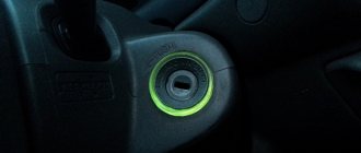
Lock lighting
Illumination of the ignition switch in a Priora car is a convenient modification in the dark. There are ways to tune anything inside your Priora. One of the most practical ways is to help yourself find the ignition switch by highlighting it. But getting a flashlight or phone out takes a long time and is impractical. Instead, you can put a backlight on this part, which will also be aesthetically pleasing to the car owner.
Such an upgrade can be purchased on Chinese websites - preferably only for Priora. To connect, climb under the steering casing, place the LED strip, and the wire soldered to it needs to be “powered.” When connected to contacts No. 8 or No. 9, when the dimensions are turned on, the backlight turns on.
Button instead of ignition switch
As a replacement, the Lada Granta and many foreign car models have a START-STOP button. We can say that the start button is a matter of driver convenience, but if you want to make your car unique, you can use different options:
- removing the standard module - the steering wheel will not be blocked;
- The standard module remains, but the steering wheel lock does not work;
- The standard module remains in place, the steering wheel lock works.
You can supply a pre-formed kit, or assemble it yourself - it will be several times cheaper, but not faster.
The cost of the set will be from 1,300 to 1,800 rubles, individual parts in total from 300 to 500 rubles.
How to put
To place a button instead of a module, perform the following steps:
- Remove the negative from the battery.
- Remove the steering casing and the plastic panel to the right of the pedal assembly.
- In accordance with the instructions that came with the start button, connect the wires to the block.
- Connect the green cable from the central unit to the brake pedal switch connector.
- The wire from the button should be connected to the three-pin connector of the central unit.
- If you need to disable the steering lock, cut off only the part of the key that fits into the cylinder and leave it in the lock in the first or second position.
- Place the key at the junction of the casing.
- Test the Start-Stop button with a few presses.
New lock installation stage
How to disable and enable the immobilizer on Kalina
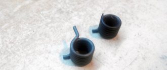
For installation, you will need the bolts used in breakaway fasteners. When a certain force is created, the edges will break off, leaving a head that the classic key will not take. As a result, the clamps will be tightened sufficiently tightly and at the same time receive additional protection.
All four bolts are screwed in the same way with the edges breaking off. The estimated cost of the castle is about 1000 rubles. Most often, special bolts may be included in the kit so as not to purchase them separately.
A replacement service will cost another few hundred. As a result, by doing everything yourself, you can save money.