Adjustment of the steering mechanism is necessary when the vehicle's directional stability is low at high speed.
This defect is associated with a violation of the adjustment of the propeller thrust bearings, and in the rack-piston-shaft-sector pair of the steering mechanism.
After adjustment, the force required to rotate the input shaft should not increase noticeably.
During operation, you should constantly monitor the condition of the hoses, especially high pressure ones. If cracks, swelling or cuts occur, hoses must be replaced.
You should also check that there are no leaks of working fluid (oil) from under the hose clamps, steering gear covers or power pump.
When the pressure in the system increases due to jamming of the bypass valve, the technological plugs in the pump casing can be squeezed out, so you should monitor the system and the quality of the working fluid being poured, top it up, replace it and change the filter in a timely manner.
You should not hold the steering wheel in extreme positions for a long time. This can lead to damage and even seizure of the booster pump.
A slight noise when the amplifier operates is not a sign of malfunction.
Checking the mechanism
If the driver notices any problems with the steering mechanism. It will be seen and heard. The steering wheel may shake and there may be a drumming sound. When turning, the steering wheel will “wedge” or “knock out”.
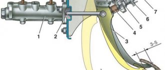
Drawing with the names of the elements of the steering column GAZ 3110
You can check the node yourself. To do this you need:
- Put the GAZ-3110 on the handbrake.
- Place supports under the rear wheels.
- Loosen the wheel on the left at the front.
- The front of the car should be raised and placed on supports.
- Remove the wheel.
- After this, remove the protective mudguard.
- In the Volga 3110 interior, completely disconnect the assembly shaft from the mechanism below.
- It is required to mark the position of the control shaft and bipod.
- Remove the bipod from the shaft.
- After removing the bolts, remove the mechanism.
This is interesting: Replacing the low beam headlight bulb GAZ-31105 2004 - 2009
Removal and installation of the steering mechanism of the Volga GAZ-3110 car
Removal
1. Set the vehicle to the parking brake.
2. Place chocks under the rear wheels.
3. Loosen the front left wheel mounting bolts.
4. Raise the front part of the car and place it on supports.
5. Unscrew the bolts and remove the wheel.
6. From the side of the wheel well, remove the mudguard from the left wheel by using a screwdriver to pry the caps securing it.
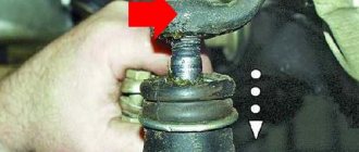
7. From inside the passenger compartment, unscrew the fastening nut 1, remove the wedge 2 and disconnect the worm shaft of the steering mechanism from the cardan joint 3.
Having previously marked the relative position of the bipod shaft 1 and the steering bipod 2, unscrew the fastening nut and press the bipod off the shaft.
Unscrew the four mounting bolts and remove the steering mechanism.
It is recommended to mark the bolts, as they are of different lengths
Disassembly
1. Clean the steering gear housing from dirt.
2. Drain the oil from the steering gear housing through the filler hole by unscrewing the plug.
It is advisable to do this immediately after the trip.
3. Clamp the steering gear housing in a vice by the boss to secure the housing to the body and set the roller to the middle position by turning its shaft 1.
Unscrew cap nut 2.
4. Remove lock washer 1 with gasket.
Unscrew adjusting screw 2.
Unscrew the four fastening bolts 3 and remove the side cover 4 with the bipod shaft assembly and the gasket.
Before removing the bipod shaft, thoroughly clean its lower end to prevent dirt from getting into the crankcase.
5. Remove side cover 3 from bipod shaft 1 together with bearing 2.
If necessary, press the bearing out of the side cover.
6. Unscrew four bolts 1 each securing the upper 2 and lower 3 crankcase covers and remove the covers together with the shim packs.
7. Remove the worm along with the roller bearings from the crankcase.
8. If necessary, remove the oil seals from the crankcase and the top cover.
Inspection and troubleshooting of steering mechanism parts
1. Check the steering gear housing.
If cracks or chips are found, the crankcase must be replaced.
2. If wear is detected on the bipod shaft bushings (the shaft has lateral play), it is necessary to replace the bushings or the crankcase with bushings assembly. 3.
Check the worm and roller.
If any chipping, cracks or dents are found, replace defective parts.
4. The bearings of the bipod shaft and the worm with the shaft should not have pitting, cavities or visible wear on the rolling surfaces.
5. If during operation traces of oil leakage were noticed, it is necessary to replace the oil seals installed in the crankcase and the top cover.
Assembly
1. The steering mechanism is assembled in the reverse order of disassembly.
Install lock washer 1 with its protrusion into the groove of adjusting screw 2, thereby securing the screw.
The lock washer itself is fixed with pin 3.
Axial play of the worm is unacceptable.
Elimination of play is carried out by selecting the thickness of the package of adjusting shims under the front crankcase cover, which ensures preload of the bearings.
In this case, the torque of turning the worm shaft should be in the range of 0.4–0.8 Nm (0.04–0.08 kgf m).
Pour 0.4 liters of TAD 17 oil into the crankcase.
Installation
Install the steering mechanism in the reverse order of removal.
In this case, the nuts securing the mechanism to the spar are tightened with a torque of 50–60 Nm (5.0–6.0 kgf m).
The bipod must be installed on the shaft in accordance with the marks.
When connecting the worm shaft to the cardan bearing, the front wheels and steering wheel must be set to the position where the vehicle is moving in a straight line.
After installation, adjust the mechanism.
Article: ShNKF.453461., additional articles: ShNKF453461.103
Order code: 029588
- Buy with this product
- show more
Steering mechanism GAZ-3110 with hydraulic booster BAGU
The design of the steering mechanism with hydraulic booster ShNKF 453461.103 (integral type) consists of a mechanical gearbox, a rotary-type hydraulic distributor and a built-in power hydraulic cylinder. Transmission type: screw - ball nut - piston rack - bevel gear sector. It differs from the steering gear with hydraulic booster ShNKF 453461.100 in improved information content regarding vehicle controllability and a reduced noise level during operation of the power steering system. Designed for installation on passenger cars. Installed on GAZ-31105, -3102 cars and their modifications.
- Maximum load on steered axle, kg: 1200
- Maximum torque on the output shaft of the mechanism at a maximum pressure of 10 MPa, Nm: 770
- Maximum permissible operating temperature of the working fluid in the vehicle's power steering system, °C: 90
- Ball screw helical groove direction: left
- Mechanism gear ratio: 17.3:1
- Full angle of rotation of the shaft sector, °: 80
- Hydraulic play, no more, degrees: 4
- Performance of the pump used with the steering mechanism, dm 3 /min: min 5 - max 7.5
- Weight, kg: 15
Information used: RUPP “Borisov plant “Autohydrousifier”.
Any motorist will say that the GAZ 3110 steering mechanism is one of the most important components of the car. Without this it is impossible to drive a car. If there is a problem with the steering mechanism assembly, then operating the GAZ-3110 is strictly prohibited. Even if there is play in the steering wheel, you need to pay attention to it. When a backlash is detected, the driver first goes to a technical inspection station to diagnose the Volga.
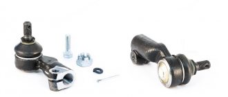
Parts for repair of the steering mechanism Gas 3110
When the cause is identified, there are 2 options for solving it. The first is to leave the car to professionals who will make the steering mechanism assembly for a fee, or figure it out yourself and eliminate the cause of the breakdown. In order to know how to fix the problem, you need to have an idea of what the GAZ-3110 steering system consists of:
Refinement of the GAZ 3110 power steering system
The car came stock with power steering... well, it would be better if it wasn’t there at all. The power steering gearbox was installed in the very first production of ShNKF 453465.100.
There were problems with the power steering system from the first day of owning the car... the pump was changed 3 times... the power steering was rebuilt 1 time... looking ahead, I’ll say that this gearbox was not completed before replacement for only 2 weeks and began to leak
There was an idea to buy this power steering kit from Avtodetalservis avtodetal.com/index.php?section=282 Here is a review from a person who bought and installed it for himself www.drive2.ru/cars/gaz/31...376151945221/#replieslist But I have to buy it like this and it failed... if only because of its cost in Ukraine. 5000 hryvnia is not a little, and that’s for Russian parts...
Well, since I couldn’t buy everything at once... I decided to take a more time-consuming and correct path.
I collected a few details like this:
1. I bought a used Volga 31105 power steering gearbox ShNKF 453461.103 link to technical specifications www.agu.by/index.php?module=view_id&vid=1299
2. Power steering pump bracket from the Avtodetalservice kit
3. Power steering pump from a Chevrolet Niva car, part number according to catalog 2123-3407012.
4. I bought a copper tube with a diameter of 13 mm, from which I bent an oil cooler for the power steering system
5. I turned a pulley of the required diameter, since it was not possible to find a ready-made one.
I also additionally bought hoses, metal corrugation, copper washers, adapters, clamps...
The purchased used power steering gearbox from the 105th Volga was sent for modification to the craftsmen at the hydrolab in Moscow (www.gidrolab.ru/price1.shtml). Such modification cost 3,500 rubles. rub. In principle, I have no complaints about them yet, but these guys did not return the bipod and driveshaft that were on the gearbox...
Came like this from Moscow
Stage No. 1 Installation of the power steering radiator: Radiator made of 13mm copper tube. is placed in place of the oil cooler. I bought good quality hoses and laid them in an iron corrugation so that the hoses did not fray or bend. The radiator is placed in the drain line from the gearbox to the expansion tank.
The radiator is fixed, the tubes are connected.
Stage No. 2 Preparing the pump for installation: Here I was faced with a choice for a long time: whether to take it from a Volkswagen, BMW, Audi or Chevrolet Niva
On the left is a pump from an Audi A6 on the right from a Chevrolet Niva... in this photo you can clearly see that they are very similar. There are differences in the angles of the hoses...
But when choosing a pump I encountered a number of problems. Firstly, the stock pressure of the Belarusian pump is 90 bar, for Audi and BMW it is 120 bar, for Niva it is 104 bar. I did not dare to take a pump with such a high operating pressure... Secondly, the cost of a good pump exceeds 3000 UAH, Chinese analogues and other fakes are no better than the Russian pump, but more expensive... In the end, I settled on a pump from a Chevrolet Niva, part number according to the catalog 2123-3407012
To install this pump on a 406 motor, you need a bracket like the one in the second photo from the top.
The Chevrolet Niva pump is sold without a pulley. And the stock pulley from this car will not suit us, because it is larger in diameter and fits a 5-ribbed belt. You need to order a turner to turn the pulley. Couldn't find a finished one. I think that no one will sell it separately during analysis... new ones, judging by Exist, have prices starting from 300 UAH. The work on making the pulley + materials cost 190 UAH.
And one more problem... The bolt that screws the high-pressure tube to the pump in the drain is 10 mm, and in the pump there is a hole for a 12 mm bolt. An adapter from one thread to another is needed... I managed to find one on the market... but the thing is very rare...
Pump assembly with bracket, pulley and adapter... ready-made design for installation on internal combustion engines
Stage No. 3 Removing the gearbox and bipod from the gearbox, more details here gazclub.ru/faq/?mess_id=450
When I removed the old gearbox... I need to remove the bipod from it, which needs to be installed on the new gearbox... those who have ever done this will understand that this procedure is more complicated than the process of removing the gearbox itself.
Damage analysis
To identify a malfunction, you need to check the crankcase. If there is a crack or chip on it, then it cannot be repaired; you need a new one.
The bushings look worn out. They also need to be replaced. You can find the crankcase assembly at points of sale of parts.
Worm and roller - if deformation is detected - replace. The bearing should be lubricated and without obvious flaws.
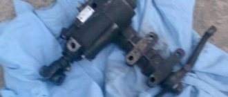
Steering columns removed from the car
If oil leaks occur from time to time, gaskets and seals need to be replaced. Reassembly is carried out in the reverse order, according to the marks made during disassembly.
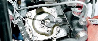
Adjusting the steering gear
Place the front wheels level. You need to place the screwdriver bottom on the steering wheel at the point at the top. Rotate the steering wheel until resistance appears. The wheels are in their original position. When finding a backlash, you need to mark the points.
If the play is 17 mm or more, you need to find this reason. If it is less than the specified distance, then the gap between the roller and the worm is simply adjusted. Remove the front wheel on the left. Using a 30mm wrench, unscrew the cap nut and remove the washer from there. Take a 12mm hex key and unscrew the clockwise adjustment screw a little. Thus, check the play on the steering wheel until it is less than 17 mm, reassemble in the reverse order.
When a crunching sound occurs in the steering wheel when driving on a bad road surface, or when driving over speed bumps. This occurs at low speeds or at high steering angles. A call to a car maintenance service is required. During diagnostics, a problem related to the steering gear may be identified.
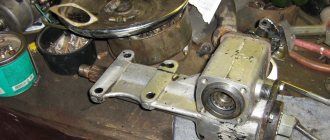
This is what the gas 3110 steering gear looks like
If you have enough money, you can leave the car in a repair shop, where the experts in their field will fix this problem by replacing it with a new one. But, if you don’t have trust or money, you can try to repair the steering gear yourself. This requires, first of all, compliance with safety rules. The presence of a pit in the garage, knowledge of the steering mechanism of the 31st Volga and all the necessary keys for disassembling and reassembling the mechanism.
The process of installing the steering column on gas 3110
Similar products
| Photo | Name | Order code | Manufacturer | Catalog number | Availability | Price, rub.) | Buy |
| Steering mechanism with power steering GAZ-3110,31105 (for spline) ShNKF.453461.103-10 | 24571 | BAGU | ShNKF.453461.103-10 | Stock | 11230 |
Pickup
- from the Auto Parts store at the address: Moscow, st. Kominterna, no. 20/2, directions ( CHECK AVAILABILITY BEFORE ). Our delivery rates
auto parts for individuals persons:
- in Moscow within the Moscow Ring Road, to the city: Mytishchi - 500 rubles.
- in the Moscow region - 500 rubles. + 40 rub. per kilometer.
- in Russia - at prices of third-party transport companies, TC "Energia" and others).
Delivery for legal entities with an order value of 15,000 rubles. in Moscow FREE
!
To pay by bank transfer, send us the details of your organization by e-mail.
Moscow, st. Comintern, 20/2. Tel.,
This is interesting: Disassembly and assembly of the oil pump drive of the Volga GAZ 31105
Steering column GAZ 3110 Volga
5.2.1 Steering column
Steering column 1 – steering wheel; 2 – nut; 3 – steering column shaft; 4 – ejector bushing; 5 – spring; 6 – contact ring; 7 – direction indicator switch; 8 – base of switches; 9 – retaining ring; 10 – washer; 11 – bearing sleeve; 1.
5.2.2 Removal
PERFORMANCE ORDER 1. Disconnect the wire from the negative terminal of the battery. 2. Remove the steering wheel (see subsection 5.2, points 2-5). 3. Unscrew the two fastening bolts and remove amplifier 1 of the instrument panel with the socket installed on it for carrying. Turned away
5.2.3 Disassembly
EXECUTION ORDER 1. Set the ignition switch to position “0” using the key, thereby disabling the anti-theft device. 2. Clamp the steering column in a vice by the eyes of the steering column pipe. Remove retaining rings 1 and washers from both ends of the steering column shaft.
5.2.4 Inspection and troubleshooting of steering column parts PERFORMANCE ORDER 1. Check the steering column pipe. There should be no cracks or dents on the pipe and bracket. Check the integrity of the welded connection between the bracket and the pipe. 2. Bearings should rotate freely by hand without noise or jamming. Check the integrity of the separators. .
5.2.5 Assembly Assembly of the steering column is carried out in the reverse order of disassembly.
5.2.6 Installation PERFORMANCE ORDER 1. Install the steering column in the reverse order of removal. Do not forget to install bushings between the steering column mounting eyes and the bracket. The tightening torques for the threaded connections securing the steering column to the bracket are 12–18 N·m (1.2–1.8 kgf·m), .
Source
Power steering repair technology
Many experts strongly recommend re-reading articles about power steering specifically for your car. Some hydraulic boosters can be disassembled almost completely, with the exception of the “ball nut - steering shaft screw” pair, while others are better left alone. Although, even if you accidentally unscrew the screw from the nut and the balls fall into the cavity of the gearbox, just do not lose them.
Read more: 1 Kilowatt is equal to ampere
Power steering repair steps:
1. To disassemble the part, take a very strong “6” hexagon, as well as a regular old tray into which ATP will begin to drain.
2. First remove the plugs from the fitting and lift the power steering above the bucket, rotating the bipod to drain the liquid.
3. Next, remove the bipod shaft and unscrew the four bolts that are mounted on the fixing mastic, and therefore are quite difficult to unscrew.
4. Unscrew the locknut of the adjusting screw, and then, turning the screw, screw it into the gearbox to push out the shaft along with the gearbox cover and bipod.
5. If you do not need to eliminate play in the bipod shaft or replace the cuff, then this bipod can be left alone and not removed. Unscrew the check valve plug.
6. Remove the spring and shake out the valve.
7. Unscrew the cover bolts and, carefully turning the shaft, make sure that it slightly pushes the cover out of the body. Be careful not to unscrew the shaft from the ball nut.
8. Pry up the resulting gap and pull the shaft along with the cover and piston out of the gearbox.
9. Remove the ball nut by unscrewing the shaft and collecting the balls.
10. Loosen the locknut and unscrew the bearing.
11. Remove the nut housing and bearings from the piston housing. Next, disassemble the nut by bending the bolt lock. Unscrew them, remove the bracket, as well as both parts of the ball guide channel.
12. We are looking for the cause of the breakdown. There can be several reasons for power steering play: gaps in the shaft-ball nut pair, in the shaft bearing unit (in the cover), as well as in the ball nut bearing unit in the piston body itself.
13. Adjust the gaps. They were formed, by the way, due to a banal loosening of the threaded connections that hold the bearing units. If play is detected in the shaft-cover assembly, then loosen the lock nut and tighten it so that the play disappears, but without fanaticism. Do not forget to carry out the “operation” cleanly, that is, the cleaned part should shine.
If you are doing this work for the first time, then do not be lazy to get detailed power steering drawings or take sheets of paper and lay out each spare part on a separate piece of paper, putting a number on it. It is ideal to work at a large table. This way you definitely won’t lose anything and will assemble the power steering without errors, and they don’t joke with the steering wheel, because this is your safety on the road, as well as your loved ones.
14. Reassemble the gearbox in reverse order, not forgetting to lubricate the parts with ATF.
Good luck, motorists, in repairing your power steering!
Do-it-yourself repair of GAS 31105
I bought myself a used steering wheel in working condition with 3110. The steering gearbox itself turned out to be 100, which has a problem with left turns, much more often than at 103m. I was thinking of sending the gearbox for modification to the hydrolab. But after reading on their website what exactly is the problem with this gearbox and what they are doing to solve this problem. I decided to try to do something myself, especially for free =). And I trust my hands more than any others.
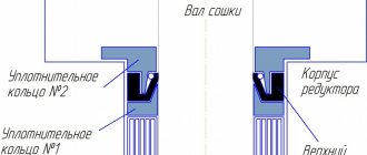
The problem is that the upper oil seal of the bipod shaft (in diagram C1, diagram from Saya Hydrolab) is cut off by high pressure (up to 100 atm) against a thrust metal ring. This is how the brain must work to make such a structure for such a loaded place. =). In the 103rd gearbox there is already a high-pressure bushing, and this problem is much less common.
After thinking a little, I decided to replace this ring with a less sharp, more regular fluoroplastic ring (you can also use caprolon). But after thinking for another day... a good idea came to me, is it possible to somehow reduce the pressure on the oil seal itself so that it is less loaded. I machined another sealing ring from fluoroplastic at the location in the gearbox housing.
It won't be entirely clear from the photo, so I sketched out a diagram.
And here are the rings and the seal themselves. The oil seal needs to be trimmed in height (from 10 to 7 mm painlessly).
Well, installed in place.
They fit tightly in the gearbox, and on the shaft itself, too, very tightly, thereby acting as the same oil seal. With this modification, there will not be such enormous pressure on the oil seal; it will be restrained by the upper ring.
I also replaced all fluoroplastic and rubber seals. I put a non-original rubber ring under the piston seal to make it tight.
After talking with one good person who is engaged in modifications, the guru advised us to seal drain cavities 1, 2, 3 (they are indicated on the gearbox diagram). And drain the area one way directly from the gearbox housing. These cavities are “parasitic.” Reduce the uniformity of pressure redistribution between the right and left working cavities. The left side already suffers due to the blunt design of the oil seal, plus the pressure in the left working cavity is reduced due to these drain cavities. To plug these drain channels, we cut threads in them and put bolts or something else on fum tape with a thread locker .
We plug the small hole in the bipod cover (this way we can block both the technological hole closed by the ball) and the mating part on the gearbox housing.
I'll tell you how I repaired the power steering pump. But first, a little background.
The steering wheel works without any complaints in a cold car in summer and winter. But as soon as the car warms up, especially in the summer, the steering wheel at idle becomes very tight, as if there is no power steering. In winter, this problem does not manifest itself as much, but it is still present. If you apply gas, the steering wheel immediately turns easier (though not quite ideally, but still easier). At the same time, the pump does not knock, does not ring, does not leak, etc... (the snotty rack is not taken into account) the oil is fresh and ideal (especially since, thanks to the condition of the rack, it is updated regularly!), the cardan is lubricated and does not stick!
Read more: Diagnostic connector gas 31105 zmz 406
In general, this is a clear sign of lack of performance of the power steering pump when the oil is hot at idle. I didn’t suffer for long, but in the end I decided to deal with this problem, spent a lot of time, scoured the Internet, understood the principle of the pump’s operation, found a similar description and decided to rebuild my “old” pump.
Disassembling the power steering pump
And so, first of all, we remove the pump, you need to drain all the liquid from it (I think everyone can figure out how to remove it and drain the liquid), and on the back cover of the power steering you need to unscrew the four bolts with a 14mm head.
After that, we begin to carefully remove the cover, try not to damage the gasket (this gasket has an internal rubber seal), in the power steering housing we leave the outer part of the “working ellipse cylinder” (hereinafter simply the cylinder). There is no need to be scared when the cover comes away from the body, it may seem that it is coming away due to the action of the spring, when reassembling it will seem to you that it does not fit into place, just continue to carefully and alternately tighten the bolts diagonally, then everything will fall into place .
Inspection and identification of defects
Carefully inspect the contents and remember (you can take a photo) what was placed where and how (more attention should be paid to the position of the cylinder). You can twist the power steering pulley and carefully use tweezers to check how the blades move in the grooves of the shaft.
All parts should be pulled out without effort, since they do not have any fixations, but the central axis is firmly fixed and cannot be removed.
We inspect the shaft from the reverse side, parts (power steering housing and cover wall) touching them, for burrs or grooves, everything is perfect for me.
Now we remove the entire internal economy onto “clean” rags and begin to study it.
We carefully examine the shaft; all its grooves have very sharp edges on all sides. One of the end sides of each groove has a pronounced sharpness inward, which, when moving the blade inside the groove with a constant slope towards this side, will greatly complicate its movement (this may be the first component of poor power steering performance). The side parts of the shaft grooves are also “sharpened”; this can be felt if you run your finger in different directions along the end (outer circumference), as well as along the side parts of the shaft in different directions. Otherwise the shaft is perfect, has no flaws or nicks.
Steering gearbox for Gazelle: diagnostics and repair
Today, the steering gear is installed on almost all modern models of Gazelle vehicles, regardless of the presence of power steering. The main function of the presented mechanism is considered to provide control of the machine, therefore the technical serviceability of the device directly affects the safety of the driver and passengers while driving.
Signs that repairs are needed
Gazelle steering gear repair
In any car, the steering parts are subject to the greatest degree of wear, since they bear heavy loads when driving on uneven roads, cornering, and sudden braking. Therefore, the Gazelle steering gear often fails, as a result of which it is urgently adjusted. The list of signs of malfunction of the unit in question usually includes:
- Vibration or knocking in the device transmitted through the steering wheel;
- Having difficulty turning the steering wheel;
- Presence of play in the gearbox;
- Oil leaks in the mechanism.
Sale of new SUVs
Repair instructions for power steering pump
As you might have guessed from the previous paragraph, if the power steering on a Gazelle does not work, then this is due to the pump. To repair this element in a car with your own hands, you will need to purchase a repair kit in advance. You can buy it at any themed store. The main difficulty in repair is that the pump is not dismountable.
The repair procedure is carried out as follows:
- Remove the pump and disassemble it according to the instructions included in the kit.
- Clean the device from dirt; there may be signs of the cause of failure on the case. Usually the problem lies in the wear of the oil seal, then it will need to be replaced. When installing a new oil seal, the shaft must be modified.
- The oil seal can be installed in several ways. You can build a special recess on the outer part of the element, drill a corresponding threaded hole in the wall of the device, and then secure the oil seal with screws. You can also fix this part in the middle of the pump using specially curved ends of the housing.
- When the replacement of the element is completed, it will be necessary to reassemble the system in the reverse order. Please note that after the repair is completed, you may hear uncharacteristic noise when the power steering is operating. This is the grinding in of the new oil seal, so there is no need to worry about this. When the repair is completed, it is necessary to change the oil in the system.
Device
Both the electric power steering on the Gazelle and the power steering are designed for more comfortable steering. First, let's analyze the power steering device on the Gazelle. We are talking about both the Gazelle Business with the 405 engine and other models in this line.
So, what is the system device:
- Power steering pump. This circuit element ensures optimal circulation of consumables in the system, as well as pressure.
- Steering gearbox with distribution element. This device allows you to provide the air flow necessary to direct the oil into the desired cylinder cavity or back into the tank.
- Another component of the system is the cylinder. With its help, the pressure of the consumable material is converted into the movement of the piston, as well as the rod.
- The consumable material itself, that is, oil. The fluid transmits force from the power steering pump to the cylinder. In addition, the oil provides lubrication of all rubbing elements of the device.