Purpose and principle of operation of the relay
What is a relay and what is it for?
Relay is an electrical device (switch) designed to close and open various sections of electrical circuits for given changes in electrical or non-electrical input quantities.
Types of relays may differ in the control signal and in design, we will not dwell on this, especially since all this is on the same Wikipedia. We only note that electric (electromagnetic) relays are most widespread. to understand why a relay is needed from the definition, so let’s break it down in simple words: The relay is designed for switching large load currents. In other words, it is a switch, or even simpler - the principle of operation of a relay - with a small current (for example, a button signal) to turn on circuits with a large current. And a relay is used when the actuator (starter, generator, fan, heated mirrors, horn, etc.) consumes more current (up to 30-40 amperes).
FOR EXAMPLE: In order to start the engine with a small button, it is necessary to turn on the starter, which consumes from 80 to 300 amperes. If you do not use a relay, then the button will not withstand high current and will melt, as well as the wiring, which is not intended for high currents. Therefore, a connection is made through a relay (a relay is installed between the button and the starter), which, based on a small current impulse from the button, closes powerful contacts within itself, thereby turning on the starter. How does this happen ?
Relay device
Relay characteristics and manufacturers
Contacts and operating principle of the relay
Some types of relays
- relay with five contacts (5-pin relay). If a signal is applied to the winding, then contact 30 is disconnected from 87a and connected to 87.
- relay with four contacts (4-pin relay). Contact 87a or 87 may be absent, then the relay will only work to turn on or off (close or open) the power circuit.
All relays have coil contacts (pins 85 and 86).
Relay circuit example
Features and service life of the relay
Features of the relay If the diode icon is shown on the relay body, then when turning it on, it is necessary to observe the polarity on the control contacts.
Relay service life If the relay has been operated for a long time when switching power circuits in extreme modes, then the spark that jumps when closing or opening the contacts creates carbon deposits between the contacts and because of this, the actuator may not work or will not work correctly. Poor contact generates heat. At the same time, the current consumption in the power circuits may increase (if the contact is poor, the current of the electric motor or light bulb becomes a pulse-start), which entails heating of the places of poor contact in the switched circuits and, as a result, melting of the plastic parts for fastening the contacts. When fastening parts melt, the contacts shift and a sparking process is added, which further heats the contact point.
The VAZ relay of the tenth family is located in various places, for example in the mounting block, on the starter, etc. Standard diagrams of the VAZ 2110 can be found here. In the comments you can post useful diagrams using relays.
How often does a relay fail in your car?
Fuse box diagram and location on VAZ-2114, 2115 and 2113
Remember one important thing, before you start disassembling the stove, wiper, headlight or anything else - make sure that the fuse responsible for this circuit has not blown. And in addition to the fuse, make sure that power is supplied to the non-working unit, because the mounting block and wiring of the car Over time, subject to external factors and influences, it may fail. The wire can most often suffer mechanical damage, the connectors can oxidize, but a track in the fuse block can burn out or even some of the conductive elements simply rot into dust.
By the way, it’s not for nothing that we focus on the latter - the location of the fuse box in the “chisel-samara” family is not entirely successful, water often gets on it, and due to the design features and its poor protection from moisture, various troubles are practically “guaranteed” by the manufacturer.
Today we will look at the diagram and location of fuses and relays VAZ 2113, 2114, 2115
VAZ 2114 fuse mounting block diagram
The fuse box in the VAZ-2114 is located under the hood, to the left in the direction of travel of the car, on the edge under the left wiper you will see a black box. To open it, you need to move two latches on the left. We remove the cover, there are relays and fuses.
There is a marking on the inside of the cover indicating the purpose of the relays and fuses.
Below are the assignments of all relays and fuses in the VAZ-2113 and 2114
K1 Relay for turning on the electric fan K2 Relay for turning indicators and hazard lights K3 Relay for windshield wipers K4 K5 Relay for turning on the power K6 Relay for turning on the sound signal K7 Relay for turning on the heated rear window K8 Relay for turning on the high beam headlights K9 relay for turning on the low beam headlights
Circuits protected by fuses
Fuse No. Protected circuits F1 (20A) Relay for turning on rear fog lights. Rear fog lamps. Rear fog lamp activation indicator F2(10A) Turn signal lamps. Relay-breaker for direction indicators and hazard warning lights (in hazard warning mode). Hazard warning lamp F3(10A) Interior lamp. Individual interior lighting lamp. Ignition switch illumination lamp. Brake light bulbs. Trip computer F4(20A) F5(20A) Sound signal. Relay for turning on the sound signal (winding). Relay for switching on the sound signal (contacts), Relay switching on the electric fan (contacts). Cooling system fan electric motor F6 (30A) Power window switches. Electric windows. Power window relay (contacts) F7 (20A) Heater motor. Washer motor. Rear window washer motor. Rear window wiper motor. Electric windshield wiper relay (winding). Glove compartment lamp F8(7.5A)Right fog lamp F9(7.5A)Left fog lamp. Relay for turning on fog lights (contacts) F10 (7.5A) Turn indicators in turn indication mode and the corresponding warning lamp. Fan motor activation relay (winding). Indicator lamp for fuel reserve, oil pressure, parking brake, brake fluid level. Battery charge indicator lamp. Instrument cluster.Voltmeter. Carburetor electro-pneumatic valve control system. Parking brake warning light relay breaker F11(7.5A) Side light bulbs on starboard side F12(7.5A) Right headlight (low beam) F13(7.5A) Left headlight (low beam) F14(7.5A) Left headlight (high beam) ). Indicator lamp for turning on the headlight high beam. F15 (7.5A) Right headlight (high beam). F16 (15A) Relay-breaker for turn signals and hazard warning lights (in turn signal mode).
Connection diagram inside the VAZ-2114 and VAZ-2115 fuse box
(the outer number in the designation of the wire tip is the number of the block, and the inner number is the conventional number of the plug)
Connection diagram of the VAZ 2114 mounting block
(the outer number in the designation of the wire tip is the number of the block, and the inner number is the conventional number of the plug): K1 – relay for turning on the headlight cleaners; K2 – relay-interrupter for direction indicators and hazard warning lights; K3 – windshield wiper relay; K4 – lamp health monitoring relay; K5 – power window relay; K6 – relay for turning on sound signals; K7 – relay for turning on the heated rear window; K8 – headlight high beam relay; K9 – relay for low beam headlights; F1-F20 – fuses
Pinout of VAZ 2114 fuse block connectors from the passenger compartment side, all connectors and pin numbers are labeled
Very often the source of the problem is moisture, especially if the storm drains are not cleaned during the operation of the car - water will then get into the engine compartment. The X11 connector especially suffers from this, up to the following consequences:
The board elements and soldering also fall into disrepair due to the systematic entry of water into the block:
What is noteworthy is that units were also produced in which the X11 connector is located not on the top, as in most cases, but on the side, here:
By the way, the circuit board of the mounting block - burnt tracks, peeling varnish, cracked soldering, oxides - everything can be restored, thereby saving quite a considerable amount, the fuse box is not a cheap pleasure. Here is an example of a restored and soldered board from block 2114 - BEFORE view:
And accordingly, after restoration work, which consisted of soldering, washing and partial replacement of connector elements + restoration of some tracks.
Well, to catch up, the left half of the circuit 2114 - 2115, thanks to which you can clearly understand the pinout of wires by color:
THIS IS INTERESTING: Bolt pattern on Lada Vesta
Electrical diagram of VAZ 2115 - 20 cars (left half):
1 – headlights; 2 – fog lights; 3 – air temperature sensor; 4 – electric motor of the engine cooling system fan; 5 – blocks connected to the wiring harness of the ignition system; 6 – engine compartment lamp switch; 7 – block for connection to a single-wire type audio signal; 8 – sound signal; 9 – washer fluid level sensor; 10 – front brake pad wear sensors; 11 – oil level sensor; 12 – generator; 13 – engine compartment lamp; 14 – coolant temperature indicator sensor; 15 – starter; 16 – battery; 17 – relay for turning on fog lights; 18 – coolant level sensor; 19 – brake fluid level sensor; 20 – reverse light switch; 21 – windshield wiper gearmotor; 22 – oil pressure warning lamp sensor; 23 – block for connecting to the rear window washer electric motor; 24 – windshield washer electric motor; 25 – instrument cluster; 26 – mounting block. Conventional numbering of plugs in blocks: A - block headlights; B — electric fuel pump block; C — blocks of the mounting block, ignition switch, windshield wiper gearmotor; D — interior lamp
Source: https://www.vazdriver.ru/blok_predohraniteley_2114/shema_i_raspolozhenie_predohraniteley_vaz_2113_2114_2115.html
How do relays work in a car?
This question sooner or later arises for almost all car owners. These little black boxes, scattered throughout the car, do something inside themselves, click, tick and sometimes break. What is a relay?
In general, relays are different. There are a huge number of relays, divided by type of operation, voltage, scope of application, and so on. But in this article, we will deal with conventional electromechanical relays that are used in any cars that you see around.
What is a relay?
A relay is a device that allows you to close or open an electrical circuit based on a specific signal. In the classic version, such a signal is a regular voltage, but applied to separate contacts. Why is this necessary?
Relays are used, firstly, so that powerful consumers of electricity can be controlled using weak control elements. Secondly, the relay makes it possible to turn on several consumers with one button.
Real life example: ordinary car headlights. Halogen headlight bulbs typically have a power rating of 55 watts. There are two of them, which means that the total power is already 110 watts. When you press a button in the cabin or turn the headlight switch, the light bulbs in the headlights light up and create a load in the wires just for these 110 watts. This power is not small, and without a relay all of it would pass through the switch. In order to implement this, it would be necessary to run thick wires into the interior, and the switch itself would be powerful and most likely ugly. It would hardly be possible to place it in the steering column switch (as, for example, on Japanese cars).
If we take into account that there are a lot of powerful consumers even in classic Zhiguli cars ( cooling fan , headlights, heated rear window, starter), then a huge number of thick wires would have to be installed into the cabin and powerful controls would have to be made.
The relay frees you from all this. To understand how it does this, let's look at its internal structure.
How does the relay work?
The basis of the relay is an electromagnet and a contact group. The contact group, in the simplest case, consists of four contacts. Two of them are power supply to the electromagnet, the rest are power supply to the consumer connected via a relay (for example, a heated rear window). These contacts have their own names - control circuit and power circuit (or control contacts and power contacts). Accordingly, the power circuit is powerful contacts that pass current through themselves to the consumer (for example, 110 Watts for headlights). The control circuit operates with a weak current and is designed to power an electromagnet. In this case, “plus” is applied to one (certain) contact of the electromagnet, and “ground” is applied to the second contact, that is, it is usually connected to the car body.
Powerful wires are connected to the power contacts, and it turns out that the relay, as it were, breaks these wires into two parts so that it is possible to control the current inside them.
igortimofeev › Blog › How automotive relays work and how to check them.
A relay acts as a remote power switch for turning on such serious current consumers in a car as a fan, radiator or glass heating.
Inside the simplest typical relay there is an electromagnet, to which a weak control signal is supplied, and a movable rocker arm, which attracts the triggered electromagnet, in turn closes two power contacts, which turn on a powerful electrical circuit. In cars, two types of relays are most often used: with a pair of normally open contacts and with three switching contacts. In the latter, when the relay is triggered, one contact closes to the common one, and the second one is disconnected from it at this time. There are, of course, more complex relays, with several groups of contacts in one housing - making, breaking, switching. But they are much less common.
The voltage indicated on the relay body is the average optimal voltage. Car relays are printed with “12V”, but they also operate at a voltage of 10 volts, and will also operate at 7-8 volts. Similarly, 14.5-14.8 volts, to which the voltage in the on-board network rises when the engine is running, does not harm them.
What is the ignition relay responsible for?
There is no power on the control wires of the main relay (GR), should it be off? From the ECU?
I don’t know what happened, but the control of the main relay did not receive the mass that I gave directly to this contact, and after that everything became normal again. The main relay is working. I checked the relay before, it worked properly, i.e. was not stuck, etc. And judging by the diagram, the mass is supplied to the control of this switch by the ECU.
serg_42
. And judging by the diagram, the mass is supplied to the control of this switch by the ECU.
Yes, there is a key in the ECU that connects this red-black wire to ground.
According to your mind, you need to pull out the ECU, pull out the relay and ring this wire. If it is in a cliff, look for where the cliff is. If the wire is intact, there is a problem in the ECU.
Well, screw it, the problem began to arise again, there is no negative from the ECU on the control wire of the main relay. Same thing again. Can this be somehow cured by soldering the key to the ECU? Someone else would show me exactly what to desolder as a replacement and solder a new one in place of the old ones
Z.Y. I found what needs to be replaced, this is TLE 6240GP, and then it will not be difficult to find it in the ECU diagram.
Z.Y. I found what needs to be replaced, this is TLE 6240GP, and then it will not be difficult to find it in the ECU diagram.
First you need to check the VD5 diode through which this switch is turned on:
Surely the diode is half dead. At the same time, ring the entire track from pin 14 of the ECU connector to pin 34 of the TLE 6240
Or will any similar diode work?
I wouldn’t hesitate to put something like KD209, 1N4007, etc. instead.
I wouldn’t hesitate to put something like KD209, 1N4007, etc. instead.
So, yesterday I opened the ECU, when the diode was tested with a Chinese tester in the resistance measurement mode, nothing happened, when the diode test mode was turned on, the diode rang as expected, after that I decided to attach the disassembled ECU to the car and check whether the minus appears on the 34th leg of the TLE, so the check failed because the minus went to the relay. And yet I think that the diode is really to blame for everything. I'll change it today. We'll see later. Why does the diode die?
Operating principle
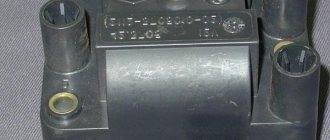
The VAZ 2114 ignition relay is structurally similar in design to other electronic relays.
Its main purpose is to start the starter and, as a result, initiate the start of the engine itself. At the same time, the relay is responsible for other equally important tasks, for example, for protecting the starter from too high voltage or, on the contrary, for starting the engine when the battery is dead (thus, it corrects the voltage in the power circuit going to the starter) .
In addition, by breaking the electrical circuit after starting the engine, the main relay thereby protects the ignition switch contacts from burning or even melting.
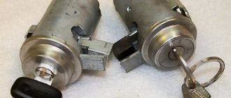
The most common ignition switch problems.
Many owners of "nines" note one unpleasant feature of their iron "horses" - that over time, the ignition switch in them simply begins to jam. Even if it was installed quite recently. Most likely, this defect is a manufacturing defect and you need to contact the store where you purchased the new ignition switch (for this purpose, it is better to save receipts for such purchases) to make a return. However, if this option is not available to you, do not despair!
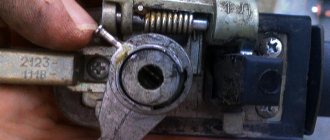
The fact is that when the ignition switch jams when starting the engine, voltage is supplied to the starter, which can lead to failure of this part. But this does not mean at all that you need to run to the auto store for a new part. In this situation, you can simply buy silicone grease and apply it inside the lock every time the lock jams.
Ignition switch consumers.
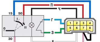
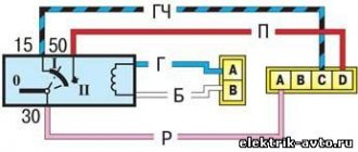
This article will be useful to those who want to upgrade the ignition switch (for example, start the engine with a button) or are experiencing problems with the lock. Only the electrical part of the lock is described. We will consider the ignition switch in the VAZ-2114 version. It, unlike the VAZ-2108 lock, works in conjunction with the ignition relay.
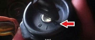
The lock has 4 positions, of which only 3 are actually used:
0 - all consumers are turned off (used extremely rarely) 1 - ignition is on 2 - starter is on 3 - parking (the key is removed from the lock) Voltage from the battery is always supplied to contacts 7 (pink) and 8 (brown) of the lock. These wires are connected in parallel and connected in the mounting block. The division into two wires was apparently done for reliability, or it may have developed historically - these wires can be replaced with one wire. The brown wire connects the ignition system (carburetor version), instrument panel and some other consumers. Pink is responsible for the rest of the load.
Signs of a relay malfunction
Sure signs that the relay has failed may include:
- interruptions in the operation of the stove fan;
- problems with turning on the windshield wipers and heated windows;
- failures to start the engine.
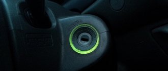
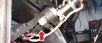
All these factors, and especially their combination, directly indicate that the device is broken and should be replaced. But before you begin the repair, you should find out where the ignition relay is located on the VAZ 2114? You should look for this electronic element under the decorative trim-casing, to the left of the steering wheel. In order to gain access to the relay, this casing must be removed.
In some cases, you can try to remove the relay without removing the casing. This can be done by carefully placing your hand underneath the casing. True, this method requires a certain skill and an accurate understanding of the location and method of attaching the relay. For this reason, when replacing the device for the first time, it is recommended to dismantle the casing.
Another, although less rare, but still common problem is overheating of the ignition relay. So, if after a long trip (during which many consumers were turned on, the operation of which is controlled by this relay - windshield wipers, glass heaters) it became very hot, then you should immediately begin searching for the cause, without waiting for the device to burn out or other problems in the on-board network.
As a rule, the high heating of the main relay is due to its low amperage in combination with a large number of consumers (the standard model 14 ignition relay is designed for a current of 70 Amps). In order to check this, it is enough to disconnect a number of devices from the relay (with the exception of the starter, of course) and check its condition after the trip.
If the relay remains cold, then the reason for overheating lies precisely in its low power. To solve this problem, you should install a new relay of a similar design, but designed for a higher current.
How to change the ignition relay
Since the ignition relay is an absolutely irreparable device, the only option for eliminating problems with it is replacement.
In order to replace the failed main relay of a VAZ 2114 with a new one (necessarily of a similar model), you will need the following set of tools:
- key to 10;
- crosshead screwdriver;
- slotted screwdriver with a thin narrow blade.
The relay replacement itself is performed in the following order:
- Disconnect the negative terminal from the battery.
- Unscrew the screws securing the protective cover of the steering column.
- Remove the casing.
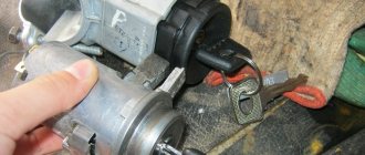
- Carefully disconnect the old relay from the block with wires.
- Connect the new relay to the block.
- Replace the protective cover and secure it.
It is worth noting that in some cases the installation location of the ignition relay may differ slightly. Sometimes, in order to get to this part, it may be necessary to dismantle not only the casing, but the entire dashboard.