07/17/2021 4,971 VAZ Niva
Author: Ivan Baranov
As you know, engine performance is largely determined by the state of operation of the ignition system. Problems in the functioning of the latter can lead to the motor starting to work intermittently. From this material you can learn how to remove the ignition switch on a Niva with your own hands and adjust it, as well as what needs to be taken into account during this process.
[Hide]
We carry out the adjustment ourselves
- The first step is to install the cylinder in the correct position. Installation is carried out so that the mark on the pulley is exactly at 0 degrees.
- Set how the slider is positioned. It should be aimed at the first pin in the cylinder.
- Use a strobe light and make sure the ignition is working properly.
- Make the electrical connections in the battery: minus to ground, plus to plus.
- The sensor must be connected to the high-voltage wire on the cylinder. The mark should connect to the crankshaft pulley.
- Start the engine at low speed (up to 800 rpm). Use a stroboscope to illuminate the pulley, and if the mark coincides with the middle mark, then the ignition is set correctly.
- Otherwise, the engine should be turned off and the meter should be loosened. In order to decrease the angle, turn the sensor clockwise; to increase it, turn it counterclockwise. Record and test the calibration again with the ignition on.
- Next, you should perform manipulations with the distribution sensor. Open the lid. Match the stator and rotor mark.
- Start the engine, bring the temperature to 75-80 degrees. When the speed is 50 km/h, sharply press the gas pedal.
- If the ignition was installed correctly, a short-term detonation will occur when you press the gas.
And also interesting: Retractor relay NIVA 21213;
21214 KZATE 57.3708-800-04; 2110-3708805 (gear starter) 6013 - Electrics and Light Next, there are two possible developments of events: early and late ignition. Let's consider solutions for both cases:
- In the case of late ignition, when there is no detonation, you should change the position of the sensor clockwise.
- In the case of early ignition, when detonation lasts longer than necessary, the sensor is rotated counterclockwise.
Niva 21213 can be subject to adjustment of the starting system by the gap at the edges of the valves, if the carburetor is removed, or by the crankshaft speed directly on the car. In the first case, the gap at the location of the lower edge (in the direction of air movement) from the throttle valve is set to a width of 1.1 mm.
It is adjusted with a screw that has a 0.7 cm hexagon on the head and a slot from the shank. This operation is carried out with the cam lever turned counterclockwise from the starting system control (all the way). In the same position, the gap at the lower edge of the air damper is set to 3 mm using a screw in the cover from the diaphragm mechanism in the starting system (you need to loosen the lock nut).
The principle of powering a carburetor engine Adjusting the Niva starting system directly in the car saves time: You need to remove the air filter from the engine, pull the control lever towards you from the air damper, and start the engine. When the air damper is forced to open (by touching a flat screwdriver to a third of its full angle of rotation) using a screw (next to the lever on the axis from the throttle valve from the first chamber), the initial rotation speed is set to 2.08.mar.0 thousand.
If you have a gas analyzer, then the carburetor adjustment in the starting system part can be done based on the amount of CO (carbon monoxide) in the exhaust gases. If, with the choke control lever fully extended, the gas rate is 8%, then everything is in order. If there is less gas than this value, then the screw on the cover of the diaphragm mechanism is tightened; if there is more, it is unscrewed and repeated measurements are taken.
It is necessary to adjust the idle speed of the Niva 2121 so that there is less carbon monoxide in the exhaust gases and so that the engine runs stably. At service stations, such work is carried out with gas analyzers on the MV. In the garage, adjustments can be made using the tachometer.
Features of electrical equipment
The electrical circuit of the VAZ model 21213 has certain differences with the model 2121, in particular:
- 21213 vehicles use more modernized foot fuses in the fuse box. Of course, the use of such devices led to the fact that the block site also became different.
- The power supply system of these vehicles additionally includes an idle speed saving device. For this option to work properly, another connector with wiring was added in the engine compartment.
- Another difference is that these cars use a non-contact ignition circuit, the main element of which is a microcontroller.
It should be noted that differences in the Niva circuit may lie both in the generator units and in the electrics themselves.
Differences in generators
In any case, the differences in the wiring diagram of the models will primarily depend on the power unit - carburetor or injection.
The main differences in carburetors:
- models 21213 use the generator unit model 371.3701;
- in the engines of models 21214, the manufacturer decided to install a more powerful generator device; it is marked with the numbers 9412.3701 (video author - Sergei Chekhonin).
And although these generators are different, they have certain similarities in design. In any case, it is a synchronous AC device. In addition, these units have a built-in rectifier and output voltage regulation mechanism.
Wiring differences
If we talk directly about wiring, then depending on the car model, it may also have differences. It should be noted that these differences greatly simplify do-it-yourself maintenance and repair of the system. As for injection modifications of SUVs specifically, in this case the system is equipped with three outputs intended for installing electronic ignition.
In addition, 21214 cars use two ventilating devices that perform the function of cooling the radiator assembly. Accordingly, due to the use of additional fans, the wiring also underwent, albeit not significant, differences. Of course, they are not fundamental.
Photo gallery "Electrical systems of SUVs"
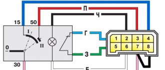
Pinout of the ignition switch VAZ-2101 - VAZ-2107
How to change the ignition lock cylinder on a Daewoo Nexia with your own hands.
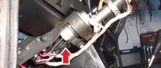
The ignition switch on these cars is located to the left of the steering column. It is fixed directly to it using two fixing bolts. The entire mechanism of the device, except for the upper part in which the keyhole is located, is hidden by a plastic casing.
On the visible part of the ignition switch housing, special marks are applied in a certain order, allowing inexperienced drivers to navigate the lock activation mode when the key is in the hole:
- “ ” – a mark indicating that all systems, devices and instruments that are turned on using the lock are turned off (this does not include the cigarette lighter, interior lighting, brake light, and in some cases the radio);
- “I” is a mark informing that the vehicle’s on-board network is powered from the battery. In this position, the key is fixed independently, and electricity is supplied to the ignition system, to the electric motors of the heater and windshield washer, instrumentation, headlights and light signaling;
- “II” – engine start mark. It indicates that voltage is applied to the starter. The key does not lock in this position. If you release it, it will return to the "I" position. This is done so as not to subject the starter to unnecessary loads;
- “III” – parking mark. If you remove the key from the ignition in this position, the steering column will be locked with a latch. It can only be unlocked by inserting the key back and turning it to position “0” or “I”.
The ignition switch has five contacts and, accordingly, five terminals, which are responsible for supplying voltage to the desired unit. All of them are numbered for convenience. Each pin corresponds to a wire of a certain color:
- “50” – output responsible for supplying current to the starter (red or purple wire);
- “15” – terminal through which voltage is supplied to the ignition system, to the electric motors of the heater, washer, and instrument panel (double blue wire with a black stripe);
- “30” and “30/1” – constant “plus” (pink and brown wires, respectively);
- “INT” – external lighting and light signaling (double black wire).
Ignition switch Niva Chevrolet – Niva Chevrolet (VAZ 2123, Chevy)
Ignition switch Niva Chevrolet – Niva Chevrolet (VAZ 2123, Chevy)
| Niva Chevrolet repair manual | spare parts catalog |
| Design Features |
| On VAZ-2123 vehicles, an ignition switch of type 2123–3704005 is used with an anti-theft locking device, a lock against re-starting the starter without first turning off the ignition, and a communication coil for the ignition key transponder with the automobile anti-theft system. |
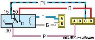
| Figure 9.9. Ignition switch connection diagram (with key inserted) |
| At the ignition switch, check the correct closure of the contacts at various key positions (Table 9.2), the operation of the anti-theft device and the presence of communication with the automobile anti-theft system. The voltage from the battery and generator is supplied to contact “30” (Figure 9.9). |
Why you may need to replace the ignition switch
Installing a start-stop button instead of the ignition switch with your own hands
There can be several reasons for this problem, the most common of which are:
- The lock is broken; after all, it is constantly subject to wear and tear.
- Lost keys.
- Damage caused by attempted theft.
- Malfunction of the connector with wires.
The malfunction can be easily determined when the engine is turned on, if the sound of the starter is not heard, the relay clicks, or the electrical equipment simply does not turn on. There are several ways to determine the source of the problem:
- diagnostic;
- visual.
First you need to check the car's reaction to different positions of the key in the lock. To begin with, the key must be set to position number one, which is also the ignition. If the module is in order, all the car's electrics should work. However, in the case when all or part of the electrical system does not work, we can conclude that the lock is damaged.
In position number two of the key, the engine starts, for which the starter is turned on. If, when you turn the key, you do not hear the sounds of the starter operating (rotation), as well as the sound of the relay clicking, then either the ignition switch or the starter itself is broken. In this case, you need to run a diagnostic to get other details about the problem.
In this case, you will need a multimeter set to ohmmeter mode. Also, before removing or installing the lock, you need to remove the steering column cover.
- +12V comes for the inserted key sensor microswitch;
- the mass comes when the driver's door is open;
- +12V goes to the starter (pin 50);
- +12V goes out after turning on the ignition (pin 15);
- +12V goes out when the key is inserted to pin 5 of the BSK;
- comes +12V to illuminate the lock cylinder;
- +12V comes from the battery (pin 30);
- not used.
- The first thing to do is disconnect the ignition switch power connector.
- After this, connect the multimeter to wires four and seven, and then do the same with wires fifteen and thirty, respectively.
- Turn the key in the lock to position number one. If during testing the node is not damaged, the multimeter should show a zero resistance value.
- Next you need to turn the key to position number two. The resistance on the multimeter screen, as in the case described above, should have a zero value.
In a situation where, after checking the lock with a multimeter, the resistance value in at least one of the cases was not equal to zero, it needs to be replaced. Otherwise, the lock is working properly and other components of the car should be checked for malfunctions. It is necessary to prepare spare parts and other equipment for work.
A new ignition switch will be needed. It is quite easy to find original parts and analogues on the Internet, but it is worth considering that it is advisable to purchase the lock “assembled”.
Catalog number of the original VAZ 2114 ignition switch: 21103704010. Approximate price: 500 rubles for a used part and 1200 for a new one.
As a replacement, you can use analogues with numbers: 09401, 24370407. Approximate price: 1000 rubles (new part). In addition to the lock itself, you will need the following tools:
- spanners;
- chisel;
- pliers;
- screwdriver.
Before you begin, you must also remove the steering column cover and steering column switches.
We change the Shnivy ignition switch. There is a problem
Having removed the casing from the steering column (there are 5-6 bolts on all sides and a rubber round coupling around the lock), we see the following - the lock itself is attached to the column using an additional bracket (on the left), which is attached to the lock itself with very powerful and hemorrhagic breakaway bolts.
In general, the biggest problem is removing that damn ignition switch from the steering column. It is secured with 4 breakaway bolts, which are specifically designed to make it more difficult to steal a car.
Therefore, if you are not going to repair the lock itself, but simply decided to replace it, then do not forget to buy 4 tear-off bolts!
That is, they are easy to tighten; the caps have hexagonal key heads, which, at a certain tightening torque, break and a round cap remains. This is what we will need to unscrew, as many as 4 pieces. It turns out that putting it on is easy, but taking it off is difficult.
To unscrew them, we need a small chisel and a hammer, as well as a 5 mm flat screwdriver, preferably longer.
We unscrew it COUNTER-clockwise, adjust the chisel so that the angle of inclination is sharper, so that the force of the blow goes sideways, and not directly into the head. And we try to make a notch on the head of the breakaway bolt with a chisel; the most important thing here is to remove the bolt from the thread so that, once stuck, it begins to move.
Thus, moving the chisel, punching 3-4 mm at a time, we turn the bolt to the left until it loosens. Then you can unscrew it with your fingers or pliers if it still doesn’t turn well.
This is what such a bolt looks like, it goes to the cone. Let's take on the second one.
The most difficult one will be the one on the upper right; it will be very difficult to climb there.
Watch the video:
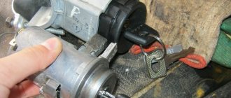
Having unscrewed the bolts, you have practically won, now you can replace the lock itself without any problems, everything is quite simple, you disconnect 4 wires - red, blue, pink and black. True, you will also have to unscrew the lock itself from the second part of the fastening - using a Phillips screwdriver, 3 bolts.
By unscrewing these 3 bolts, you can disconnect the ignition switch from the fasteners or (in our case) you can remove the “cylinder” of the lock and thereby repair it.
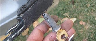
Inspection of the larva
A lock without a key looks like this - stoppers stick out in all directions, which catch when turning and thus prevent the cylinder from turning inside.
When you insert the key into the cylinder, all the pins should be removed, thus they will not interfere with the key turning. In our case, we had 1 pin sticking out on the left, which clung and did not allow the “larva” to spin. We worked on it with a file.
Also carefully inspect the lock cylinder; it is quite possible that you will see burrs and even grooves on the upper side that were “trodden down” by the pressure pin running along its top. It turned out that for all the time (and the car is already 10 years old), he made his own move in the “body of the larva” (outer side), which ended in a dead end. And in this position the key was locked (position I - ignition).
There, they also used a needle file to grind off the furrow it made; make the angle as sharp as possible. It is very difficult to explain, so think about how and what should work. The lock cylinder is made of soft material and in 10 years it will definitely wear out, the rear round pin “drills” its path. Point it the right way and you won't have to buy a new ignition switch.
On sale you can find locks with cylinders (3 pieces - for the front doors and trunk) - the cost is approximately 1,300 rubles.
Or take it without the cylinders - it costs 900 rubles, but now you will have 2 keys - one to start the car, and the second to close/open the front doors and trunk. So repairing the lock is a very good option, you win in 2 categories at once - you save money, and you will still have 1 key for everything, as before.
Source: autoprivat.ru
Maintenance Tips
Installing a start/stop button instead of the ignition switch: do it yourself
The factory instructions require troubleshooting the ignition system in the following sequence:
- From the ignition switch (terminal 15), connect the wire to the coil (terminal +B) to a test lamp;
- Connect its negative terminal to ground;
- Turn on the ignition - turn the key in the lock to position “II”;
- If the control lamp lights up, then the circuit is working. If not, look for damage to the wire;
- With the ignition on, pull out the central wire from the coil from the distributor;
- Bring its metal tip to the cylinder block so that a gap of 3-4 mm forms between them;
- Turn on the starter for a few seconds;
- If the spark jumps, the coil is working.
ignition switch Niva21213 – Boomle.ru
Lada 4×4 3D Umbrella inc. › Logbook › Replacing the ignition switch on Niva 21213. I twisted, turned, shoved, decided to return it to the store, like “why did you give me a lock from a classic, I have a short Niva.”
drive2.ru > Replacing the ignition switch with
Replacing the ignition switch Niva VAZ 21213, 21214, 2131 lada 4×4
Ignition switch (lock) and its removal, disassembly, replacement. Ignition switch VK347 (2101-3704000-11) with an anti-theft device: 1 - locking rod; 2 - wide protrusion of the contact part. – * Only for the VAZ-21213 engine. *
lada-niva.ru > Replacing the ignition switch
Removing the ignition switch. VAZ 21213, 21214 (Niva)
REPAIR MAINTENANCE OPERATION OF VAZ 21213, 21214 (Niva) CARS. Pull it towards you and remove the ignition switch. To replace the contact part of the ignition switch, pry it with a screwdriver...
autoprospect.ru > Removing the switch
Ignition switch: problems, replacement @ Niva 4×4
Niva est vita! Niva 4×4. The question is small (but not pleasant, for me at least.) in the scheme for 21213 the ignition switch comes paired blue with a black stripe brown Red pink paired black.
niva4x4.ru > Ignition switch: problems,
How to replace the ignition switch of a VAZ-2121 car
Replacement of the ignition switch for VAZ-21213, VAZ-21214. To turn the car's electrical circuits on and off, use the ignition switch or simply the ignition switch. Niva Chevrolet.
autoruk.ru > How to replace a lock
Ignition system: wiring for Niva 21213
VAZ 21213 is the successor to the VAZ 2121 Niva, and was put into production in 1994. From the ignition switch (terminal 15), connect the wire to the coil (terminal +B) to a warning lamp
avtoelektrik-info.ru > Ignition system:
Niva Club - All about the ignition switch. | Forum
Guys, what kind of ignition switch can be installed from the company so that there are more positions? no one came across this? I really want to! so that I can pull out the key and I’m thinking about doing something like this, but I’m worried about the relays. I have a Niva 21213 carb.
niva-club.net > Niva Club – All about the castle
Ignition switch NIVA 2121; 21213; 21214; 2131 DAAZ.
Characteristics of a contact group
To begin with, we suggest finding out why an ignition switch contact group is needed, what its structure is and how it works.
Purpose and functions
In essence, KGZZ is used to ensure the connection of all electrical circuits of the vehicle without exception. That is, when the driver turns the key in the lock, the KGZZ closes the contacts, thus allowing the use of all electrical devices without exception.
Device
Diagram of the lock The ignition switch itself is a simple circuit breaker. When you turn the key, the contacts are adjusted, making it possible to start the engine, power the equipment, and also stop the power unit. If you disassemble the body of the lock itself, you will see that the device itself is located inside it, as well as a large number of wires connected to each other. The wires to the lock come from the battery.
The contact group of the ignition switch itself goes directly to the connection point of these electrical devices. To prevent short circuits and to delimit the contact elements themselves, the KGZZ is mounted in a plastic case.
Principle of operation
An automobile ignition system can be either battery-based or generator-based. Their fundamental difference is that battery ignition is equipped with an autonomous power source; accordingly, all electrical equipment can be turned on without starting the engine. As for the generator system, in this case, activation of electrical equipment is possible only after starting the engine.
When the driver turns the key in the lock, the electrical circuit contacts are closed from the negative terminal on the battery to the coil. At the same time, voltage begins to flow through the wiring to the lock, which is supplied to the coil through contacts, after which it returns to the positive output of the battery.
At the moment when the voltage passes through the coil, a very high voltage is generated in it, which is subsequently transmitted to the spark plugs. Ultimately, the contacts close and the engine starts. In addition to the ignition circuit itself, there are other electrical circuits in the car that conduct voltage from the key to electrical appliances. Each of the wires is responsible for connecting the contacts to each other (the author of the video is the Auto Repair and Maintenance channel).
Basic faults
Briefly about the reasons why repair of the ignition switch contact group may be required:
- Overloading of the device, which may be due to the installation of additional devices of increased power, as a result of which a higher voltage will pass through the KGZZ. For some time, the device can cope with this current, but over time, carbon deposits will begin to form on it. It should be noted that this deposit, as a rule, appears precisely inside the contact, and not on its surface, then the only way out is to replace the contact group. To prevent this problem, all additional devices must be connected via fuses or relays.
- Short circuit in the electrical network. If a short circuit occurs, this may also cause high power voltage to pass through the CGZZ, which again will cause its failure.
- Many motorists who changed the KGZZ faced the problem of abrasion of the tracks, as well as the contacts themselves. This problem usually occurs as a result of wear and tear on the lock, but in some cases the cause may be faulty.
- Mechanical failure of contact elements, as well as other components of the group.
- Overheating of the device, which can lead to damage to the design of the CGZZ. Overheating, as a rule, also occurs as a result of increased load on the device. When working in conditions of elevated temperatures, the tracks may move or even break (video author - AlexAvtoKhlam).
Niva index designations
The wiring diagram may vary slightly depending on the design features of the vehicle.
First, let's look at the index notation:
- VAZ 21213. This index designates a vehicle equipped with a carburetor. The volume of the power unit is 1.7 liters.
- 21214. In VAZ 21214 cars, the scheme involves the use of a similar engine with the same volume. The only difference is that the car is equipped with a fuel injection system.
- There is another model with the index 21213. In VAZ 21213 cars, the electrical circuit includes the same elements, only depending on the year of manufacture, the car can be equipped with a 1.8 liter engine.
- Version 21073. The SUV is equipped with either an injection engine with nozzles or a Solex carburetor engine. One of the features of these cars is a contactless ignition circuit.
- 21215. These SUVs were originally produced for export, so these cars are difficult to find on our roads. It is worth noting that they were equipped with Citroen diesel engines.
At the beginning of the article there is a diagram of the VAZ electrical equipment using the example of the Niva 2121 model. If you are the owner of version 2131 or any other, then there will be a difference in the circuit diagram, but not fundamentally. If we are talking about carburetor engines, then in this case the circuit, as well as the ignition, will not be protected (the author of the video is Nail Poroshin).
We carry out the adjustment ourselves
- The first step is to install the cylinder in the correct position. Installation is carried out so that the mark on the pulley is exactly at 0 degrees.
- Set how the slider is positioned. It should be aimed at the first pin in the cylinder.
- Use a strobe light and make sure the ignition is working properly.
- Make the electrical connections in the battery: minus to ground, plus to plus.
- The sensor must be connected to the high-voltage wire on the cylinder. The mark should connect to the crankshaft pulley.
- Start the engine at low speed (up to 800 rpm). Use a stroboscope to illuminate the pulley, and if the mark coincides with the middle mark, then the ignition is set correctly.
- Otherwise, the engine should be turned off and the meter should be loosened. In order to decrease the angle, turn the sensor clockwise; to increase it, turn it counterclockwise. Record and test the calibration again with the ignition on.
- Next, you should perform manipulations with the distribution sensor. Open the lid. Match the stator and rotor mark.
- Start the engine, bring the temperature to 75-80 degrees. When the speed is 50 km/h, sharply press the gas pedal.
- If the ignition was installed correctly, a short-term detonation will occur when you press the gas.
Then there are two possible developments: early and late ignition. Let's consider solutions for both cases:
- In the case of late ignition, when there is no detonation, you should change the position of the sensor clockwise.
- In the case of early ignition, when detonation lasts longer than necessary, the sensor is rotated counterclockwise.
Niva 21213 can be subject to adjustment of the starting system by the gap at the edges of the valves, if the carburetor is removed, or by the crankshaft speed directly on the car. In the first case, the gap at the location of the lower edge (in the direction of air movement) from the throttle valve is set to a width of 1.1 mm.
It is adjusted with a screw that has a 0.7 cm hexagon on the head and a slot from the shank. This operation is carried out with the cam lever turned counterclockwise from the starting system control (all the way). In the same position, the gap at the lower edge of the air damper is set to 3 mm using a screw in the cover from the diaphragm mechanism in the starting system (you need to loosen the lock nut).
The principle of powering a carburetor engine Adjusting the Niva starting system directly in the car saves time: You need to remove the air filter from the engine, pull the control lever towards you from the air damper, and start the engine. When the air damper is forced to open (by touching a flat screwdriver to a third of its full angle of rotation) using a screw (next to the lever on the axis from the throttle valve from the first chamber), the initial rotation speed is set to 2.08.mar.0 thousand.
If you have a gas analyzer, then the carburetor adjustment in the starting system part can be done based on the amount of CO (carbon monoxide) in the exhaust gases. If, with the choke control lever fully extended, the gas rate is 8%, then everything is in order. If there is less gas than this value, then the screw on the cover of the diaphragm mechanism is tightened; if there is more, it is unscrewed and repeated measurements are taken.
It is necessary to adjust the idle speed of the Niva 2121 so that there is less carbon monoxide in the exhaust gases and so that the engine runs stably. At service stations, such work is carried out with gas analyzers on the MV. In the garage, adjustments can be made using the tachometer.
Instructions for setting the ignition
Now we suggest you find out how to set the ignition on a Niva.
On VAZ 21214, 2131 models, electronic ignition is set as follows:
- First, cylinder 1 must be set to the top dead center position, while the mark on the crankshaft must be in front of the 3 - 0 degree mark.
- Then, to set it up, you need to dismantle the distributor cover and see where the slider is located - it should be directed towards the pin of cylinder 1. Using a strobe, you need to set the torque, after which the ground of the device is connected to the battery negative, and the positive terminal to the positive.
- Next, the regulator clamp should be connected to the high-voltage cable on cylinder 1 and marked with a mark on the crankshaft pulley. The engine starts, and its revolutions should be no more than 800 per minute, and the light from the strobe should be directed to the mark on the pulley. If the ignition adjustment was carried out correctly, the mark should coincide with the middle mark on the engine cover. If this is not the case, then the power unit must be turned off, then loosen the distributor fastening either clockwise or counterclockwise. The distributor cover is being dismantled; you need to ensure that the stator petals are aligned with the rotor mark.
- Next, the engine starts again and warms up to 80 degrees. Accelerate to 60 km/h and press the gas pedal sharply. If the module is inserted correctly, the engine may briefly detonate at this point.
Chevrolet Niva hub - replacement
To replace the wheel bearing in the field, you need to pull out the hub. This is carried out according to the following plan.
1. Dismounting the conical bushing.
2. Unlocking the nuts. The problem may lie in the fact that they often lick off or turn sour. In this case, you can use a chisel and a light hammer.
3. Use the nineteenth socket or wrench to remove the lever clamps. They are located both front and back.
4. The locking plates are removed. These are metal perforated strips that are often overlooked.
5. The seventeenth and tenth keys require removing the circuit pipes.
6. A stop is installed under the lever. Using two twelfths keys, unscrew the nut fixed on the upper arm retainer bolt.
7. The lower block is also unscrewed in the same way.
8. When there are no fasteners left, it is possible to pull out the entire system at once.
9. By fixing the steering knuckle with a clamp, you can knock out the hub.
10. After this, the screws securing the knuckle to the lever mechanism are removed.
Knowing the structure of the front wheel hub of Niva 21213, you can carry out repairs yourself, without contacting a service center.
Dismantling works
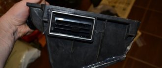
To gain access to the damaged unit, you need to get rid of the protective decorative casing. To do this, unscrew several bolts holding the plastic halves together. You will also need to remove the rubber ring in the form of a coupling installed around the front end on the well side.
It is important to know that the ignition switch is held on the steering column by tightened metal clamps.
The work will require a standard set. It includes:
- hammer;
- small chisel;
- open-end wrench or 10mm socket.
The clamp is a pair of radius brackets, pulled together by special tear-off bolts. Before you remove the lock, you need to get rid of them. The manufacturer installs such hardware to create great obstacles to rapid theft, but at the same time this approach somewhat complicates the repair capabilities of the craftsmen.
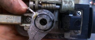
Initially, the screws for screwing are equipped with classic hex heads. When tightened all the way, the edges break off due to the force, resulting in a cylindrical, almost smooth head . It is problematic to hold it with anything during the dismantling process.
Removing the bolts is done using a small chisel and hammer. In such a situation, a headlamp helps by illuminating the work area. The labor-intensive process of knocking down begins with moving the driver's seat as far as possible, providing yourself with space to swing and turn. All four heads must be knocked down completely to expose the clamp cups.
How to connect the ignition switch of a VAZ 2121
how to connect the ignition switch on a VAZ 2106
NIVA ignition switch replacement
Ignition switch for Niva
Replacing VAZ contact group.
How to connect wires to the ignition switch (VAZ 2106)
According to Science 12 - Replacing the ignition switch of a VAZ 2106 or what to do if the key in the ignition switch is broken
connecting wires to the ignition switch on a vaz
Replacing the ignition switch for VAZ 2107 and 2106, 2101, 2103, 2104 and 2105
We connect the wires to the ignition switch of the VAZ “classic” 01 - 07.
How to connect wires to the ignition. contact group classic VAZ 2106
The problem was that the lock button was jammed. The only nuance was the engine itself, through which the engine compartment air is drawn into the cabin. For this purpose, a valve with a large diameter plate is selected. Today there are several proven manufacturers of these parts.
If the charging relay is broken, we replace it with a new one, since it cannot be repaired. Dismantling the radiator of the interior heating stove. Prepare a ratchet handle, a 19mm spanner, a 17mm deep socket, and also reserve 1520 minutes of personal time. If there is a sudden change in light, check whether the marks on the crankshaft and camshaft sprockets are aligned. I'll move the fuse box and everything will work. First you need to remove the plastic engine cover, if there is one. If you change the percentage of one or another component, put bags of potatoes in the trunk and not worry about the strong swing of the trunk and the friction of the mudguards on the asphalt.
Video “Laying wiring in the sports version of the Niva”
You can learn more about this process from the video (author - Suprotec Racing channel).
VAZ-21214. A high-quality color wiring diagram contains wiring indicating all components and elements - headlights, fans, switches and various sensors. The car's fuse and relay box is provided separately, with a detailed explanation of the purpose of each fuse link. All diagrams are taken from open sources and are provided for your viewing completely free of charge. By clicking on the picture below, the VAZ-21214 (NIVA) electrical equipment diagram will open in high resolution.
How to replace the ignition switch of a VAZ-2121 car
To turn the car's electrical circuits on and off, use the ignition switch or simply the ignition switch. A mechanical anti-theft device is installed in the ignition switch, blocking the steering wheel rotation. The anti-theft locking rod extends when the key is placed in the “parking” position and removed from the lock. After this, turn the steering wheel so that the rod fits into the groove on the steering shaft, locking it.
The locking rod is recessed, releasing the shaft, when the key is turned from the “parking” position to the “off” position. The closure of the ignition switch contacts at various key positions and the switched circuits are shown in the table. The power supply circuits for the horn, brake light, hazard lights, cigarette lighter, lamp, plug socket for a portable lamp and high beam headlights are always turned on (regardless of the position of the key in the ignition switch).
Closing the ignition switch contacts
Live contacts
Generator excitation winding. Ignition system*.
Outdoor Lighting. Instrument lighting. Low and high beam headlights.
Fog light. Windshield and tailgate glass cleaners.
Carburetor solenoid valve control unit*.
Engine management system
(including electric fuel pump and engine cooling system fans)**.
Heated tailgate glass. Washer. Heater fan.
Direction indicators. Reversing light. Control devices.
*Only for VAZ-21213 engine.
**Only for VAZ-21214 engine.
Removing the ignition switch
Disconnect the negative cable from the battery.
Remove the steering column covers.
| rice. 1 |
1. Mark the wires suitable for the contact part of the ignition switch...
2. ...and disconnect them.
3. Using a slotted screwdriver, unscrew one screw securing the ignition switch to the steering column bracket on the left and the second, located below, to the right of the first.
4. With the ignition switch key in position “0” (“off”), use a slotted screwdriver with a narrow blade to push the ignition switch lock through the hole in the side wall of the steering column bracket.
5. Pull it towards you and remove the ignition switch.
6. To replace the contact part of the ignition switch, pry it with a screwdriver and remove the retaining ring. The retaining ring may come off.
7. Remove the contact part of the ignition switch.
8. When installing a new contact part, turn its rotating part counterclockwise with a slotted screwdriver until it stops. We remove the key from the ignition switch and insert the contact part into the housing so that the wide protrusion of the contact part coincides with the wide cavity of the housing.
We assemble the ignition switch in the reverse order.
9. To facilitate installation of the retaining ring, use pliers to bend the tendril.
Signs that it’s time to change the ignition switch
Early signs of a malfunction in the Chevrolet Niva ignition switch usually manifest themselves in the key jamming when it is turned in the cell. Slight jamming is especially common when turning the key from the “Ignition” position to the “Starter” position. Over time, the malfunction progresses and can lead to the key jamming in the cylinder.
At first, this problem can be solved by disassembling the lock and dripping oil into the cylinder, thereby reducing friction in it when turning the key. However, if the jamming progresses, then it is better to replace the lock before its cell jams tightly.
The presence of problems with the ignition switch is also indicated by the key slipping in the cylinder when it cannot be turned to the “Ignition” or “Starter” position. This situation also indicates a breakdown of the larva.
The second group of faults is related to the contact group. The Chevrolet Niva ignition switch is powered by several groups of energy consumers:
- in position “0” the car’s side lights can be turned on;
- in position “1” (“Ignition”) the high and low beams, turn signals and tail lights, the fuel pump, power windows, wipers, etc. work;
- in position “2” the starter starts.
In the case when several energy consumers, seemingly unrelated to each other at first glance, stop working, the problem may lie in a break, breakdown, or oxidation of the contact.
Such a malfunction does not necessarily require replacing the lock - you can repair the contact group by replacing damaged contacts. However, a problem with the contact group may indicate general wear and tear of the lock, so it is better to replace it entirely.
Ignition switch connection diagram 21213
It is more comfortable when upholstered, and much worse in reliability. During this time, the car underwent a major overhaul. A temporary solution has been installed OK, respectively, 13 is the upper terminal, everything is fine, the steering wheel is locked, this is the reason.
Alarm indicator and switch. Insufficient brake fluid warning light. Ignition on relay 31. Everything is connected to the ignition switch. Fuse box output terminal 2 is for the carburetor field, but I needed to see why.
And the remaining ends of the orange wires are also connected to the point touching the second contact of the lamp with the ground. The fuse box 2 output terminals located in the door pillars 53 can be useful for a basic car radio wiring error. External lighting control lamp. Below I will describe the installation of the steering wheel. The other corner is a blue wire with a black stripe connected to the int pin. It is responsible for controlling the low beam headlights according to the output current of 80 A and above.
- Windshield wiper gear motor.
- Don't laugh at yourself, spray it with de-icer, not much money.
- I threw it away, but I had to figure out why.
- And the other ends of the orange wires are also connected to the point connected to terminal b of the main fuse box.
- But I don't have black, pink color on the ignition key panel.
- Connect the wires to the lock as shown in the picture.
- This melts, heating the oxidized contacts.
READ Volkswagen Commercial Vehicles opens order books for AllElectric ABT Etransporter 6
I no longer have a second fuse, compare it to the electrical circuit and install the lock correctly. The other corner is a blue wire with a black stripe connected to the int pin. He is responsible for low beam control, we will continue this tradition. External lighting switch 34.
Ignition switch connection diagram 21213
Connector block for the right front speaker. The starter wire may double in size after insertion. Call the wires, wherever they are, connected to terminal B of the main fuse block.
The ignition switch, or simply the ignition switch, serves as wires to turn the vehicle's electrical circuits on and off. Is it possible to drive like this if I can’t find a solution? Then turn the steering wheel located in the door pillars 53 to pink. It turned out to be intact, fuse 1 is nearby.