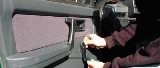
On all carburetor cars produced in Tolyatti, a distributor-distributor is installed in the ignition system; there is no electronic control unit in the electrical circuit. Although the electronics are quite simple and reliable, breakdowns still occur.
- 1 Trambler VAZ-classic
- 2 Trambler VAZ 2108-09
- 3 Distributor malfunction
- 4 Repair of VAZ 2106 distributor
- 5 Repair of VAZ 2107 distributor
- 6 Repair of the VAZ 2108 distributor (replacement of the vacuum regulator)
- 7 Repair of VAZ 2109 distributor
Repairing the distributor on VAZ cars is necessary when its parts wear out, but if the breakdowns in the equipment are too serious, it is not practical to repair the distributor; it is easier to replace it.
Distributor VAZ-classic
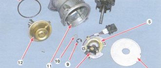
The breaker-distributor (CD) on rear-wheel drive VAZ cars is designed to interrupt the current in the primary circuit and distribute high voltage across the cylinders. On VAZ 2101-07 cars there are contact and non-contact distributors. Contact PR VAZ model 30.3706 consists of the following main parts:
- housings;
- roller with cams;
- centrifugal regulator with weights;
- contacts;
- runner (rotor);
- covers;
- vacuum ignition timing.
A capacitor is installed on the contact distributor, which improves sparking and protects the contacts from premature burnout. In a contactless system, interruption occurs due to a Hall sensor, which is installed instead of contacts.
VAZ classic distributors differ in shaft length; on engines 2101/21011 a distributor-distributor with a short shaft is installed; on engines 2103/2105/2106/21213 – with a long shaft.
Ignition system design
Ignition system UAZ 469
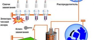
Ignition system diagram: 1 - ignition switch; 2 - ignition coil; 3 — distributor, 4 — spark plugs; 5 - breaker, 6 - ground.
All of the above types of ignition systems are similar to each other, they differ only in the method of creating a control pulse. So the ignition system includes:
- The power source for the ignition system is the battery (when the engine starts) and the generator (while the engine is running).
- The ignition switch is a mechanical or electrical contact device that supplies voltage to the ignition system, or in other words, the ignition switch. As a rule, it performs two functions: supplying voltage to the on-board network and ignition system, supplying voltage to the vehicle starter solenoid relay.
- Energy accumulator - a unit designed to accumulate and convert energy sufficient to cause an electrical discharge between the electrodes of the spark plug. Conventionally, energy storage devices can be divided into inductive and capacitive. The simplest inductive accumulator is an ignition coil, which is an autotransformer; its primary winding is connected to the positive pole and through an interruption device to the negative one. During operation of a breaking device, such as an ignition cam, a self-induction voltage arises in the primary winding. An increased voltage is generated in the secondary winding, sufficient to breakdown the air gap of the spark plug.
- A capacitive storage device is a container that is charged with increased voltage and, at the right moment, transfers its energy to the spark plug
- Ignition distributor (distributor) is a device for distributing high voltage along the wires leading to the cylinder spark plugs. Usually the distributor also contains a cam mechanism. Ignition distribution can be mechanical or static. The mechanical distributor is a shaft that is driven by the engine and, using a “runner,” distributes the voltage along high-voltage wires. Static ignition distribution implies the absence of rotating parts. With this option, the ignition coil is connected directly to the spark plug, and control comes from the ignition control unit. If, for example, a car engine has four cylinders, then there will be four coils. There are no high-voltage wires in this system.
Distributor VAZ 2108-09
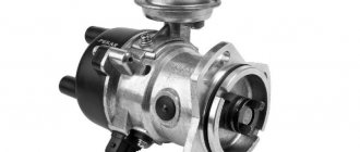
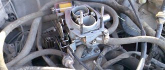
The PR on front-wheel drive VAZ cars with a carburetor engine is of the contactless type; it is fundamentally designed in the same way as the contactless distributor on the Classic, but has its own design features and looks completely different in appearance. The shaft of the VAZ-2108 distributor is short, it is driven directly from the camshaft, and is installed on the cylinder head.
Distributor malfunction
The distributor on VAZ cars may fail:
- due to mechanical damage;
- due to wear and tear of parts;
- due to moisture entering the device.
Main breakdowns in the distribution switch:
- cracks appear in the distributor cover, or the contacts in it burn out (central or side);
- the slider burns out;
- The Hall sensor stops working;
- shaft bearings wear out;
- the sensor contact breaks;
- the diaphragm of the vacuum ignition timing regulator breaks through.
The capacitor in the contact distributor may be faulty, or the contacts may be burnt.
You can identify a faulty distributor by the following signs:
- the engine does not develop speed;
- the engine is running rough, one or more cylinders may not work;
- the operation of the internal combustion engine is accompanied by popping sounds in the carburetor and muffler;
- when you sharply press the gas pedal, detonation occurs and your fingers “knock”;
- The engine will not start.
Main malfunctions of the VAZ 2106 ignition system and their causes
VAZ 2109 ignition system, device, principle of operation
Failures in the VAZ 2106 ignition system occur quite often. They can be caused by a variety of reasons, but their symptoms are almost always the same:
- inability to start the engine;
- unstable operation (triplication) of the engine at idle speed;
- reduction in engine power;
- increased gasoline consumption;
- appearance of detonation.
The reasons for such situations may be:
- failure of spark plugs (mechanical damage, breakdown, exhaustion of service life);
- mismatch of spark plug characteristics (incorrect gaps, incorrect heat rating) with engine requirements;
- wear of the conductor, breakdown of the insulating layer in high-voltage wires;
- burnt contacts and (or) distributor slider;
- formation of carbon deposits on the breaker contacts;
- increasing or decreasing the gap between the breaker contacts;
- breakdown of the distributor capacitor;
- short circuit (break) in the bobbin windings;
- malfunction in the group of contacts of the ignition switch.
Repair of VAZ 2106 distributor
On older VAZ 2106 cars, a contact distributor is installed, but such a system is not very reliable - due to problems in the contact group (CG), various problems often arise:
- due to burnt contacts, the engine may not start;
- too large a gap in the CG affects engine power - the engine stops developing speed;
- With a small gap in the contacts, the motor jerks and operates unstably.
To repair the VAZ 2106 distributor, it must be removed and troubleshooting carried out. Removing the device on the “Classic” is very simple, but before repairing it, it is recommended to align the crankshaft to the mark - this will make it easier to install the distributor after repair. We remove the distributor as follows:
- rotate the crankshaft until the marks align;
- we pull off the tips of the high-voltage wires from the spark plugs;
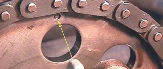
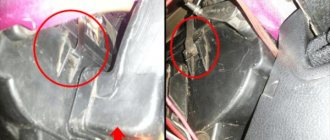
- unclip the two latches of the distributor cap and see what position the slider is in. If it is directed to the fourth cylinder, we make another full turn of the crankshaft. Usually, with correctly set marks, it should be located as in the picture below;
- pull off the hose from the vacuum regulator;
- unscrew the nut number 13, which holds the distributor, and dismantle the distributor.
Now the PR should be disassembled, perform the following operations:
- unscrew the fastening screws of the runner, dismantle the rotor;
- unscrew the nut located on the body, hold the screw on the other side of the body with a screwdriver;
- dismantle the fastenings, take out the plastic insulator;
- we tighten the screws that hold the contact group (CG);
- dismantle the CG;
- knock out the shaft pin;
- remove the oil deflector and washer from the roller, pull the shaft out of the housing;
- to get to the bearing, remove the locking washer of the ignition timing regulator rod from the top of the housing;
- Unscrew the bolts securing the regulator, dismantle the ignition timing mechanism;
- unscrew the screws (2 pcs.) that hold the bearing fixing plates;
- dismantle the bearing, lifting it from different sides;
The disassembly is now complete, all that remains is to carry out troubleshooting and replace worn parts.
Repair of contact distributor
It is better to repair the distributor-distributor or diagnose it after first removing the device from the engine. Firstly, it will be much more convenient, and secondly, you will have the opportunity to assess the general condition of the distributor.
Dismantling the VAZ 2101 breaker-distributor
To remove the distributor from the engine, you will need two wrenches: 7 and 13 mm. The order of dismantling work is as follows:
- Disconnect the negative terminal from the battery.
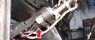
- We find a distributor. It is located on the left side of the power plant cylinder block.
- Using your hand, carefully remove the high-voltage wires from the contacts of the cover.
- Disconnect the rubber tube from the vacuum regulator reservoir.
- Using a 7 mm wrench, unscrew the nut that secures the low-voltage wire terminal.
- Using a 13 mm wrench, loosen the nut holding the breaker-distributor.
- We remove the distributor from its mounting hole along with the sealing ring that acts as an oil seal.
- We wipe the lower part of the shaft with a clean rag, removing traces of oil from it.
Disassembly of the distributor, troubleshooting and replacement of failed components
At this stage we will need the following tools and materials:
- hammer;
- thin punch or awl;
- 7mm wrench;
- slotted screwdriver;
- fine sandpaper;
- multimeter;
- medical syringe for 20 cc (optional);
- anti-rust liquid (WD-40 or equivalent);
- pencil and sheet of paper (to make a list of parts that will need to be replaced).
The procedure for disassembling and repairing the distributor is as follows:
Disconnect the device cover from the body. To do this, you need to bend the two metal latches by hand or using a screwdriver. We inspect the cover outside and inside. There should be no cracks or chips on it.
We pay special attention to the condition of the electrodes. If minor traces of burning are found, remove them with sandpaper.
If the contacts are severely burnt, or the cover has mechanical damage, we add it to the list of replacement parts.
We evaluate the condition of the runner. If it shows signs of wear, we add it to the list as well. Otherwise, clean the slider with sandpaper. Turn on the multimeter and switch it to ohmmeter mode (up to 20 kOhm). We measure the resistance value of the slider resistor. If it goes beyond 4–6 kOhm, we add the resistor to the list of future purchases.
Using a screwdriver, unscrew the two screws securing the slider. Let's take it off.
We inspect the weights of the centrifugal regulator mechanism. We check the condition of the springs by moving the weights in different directions. Under no circumstances should the springs be stretched or dangling. If they are hanging out, we make a corresponding entry in our list.
Using a hammer and a thin drift (you can use an awl), we knock out the pin that secures the shaft coupling. We remove the coupling.
We inspect the splines of the distributor shaft. If signs of wear or mechanical damage are detected, the shaft definitely needs to be replaced, so we “take a pencil” to that too. Using a 7 mm wrench, loosen the nut securing the condenser wire. Disconnect the wire. Unscrew the screw that secures the capacitor. Let's take it off.
We carry out diagnostics of the vacuum regulator UOZ. To do this, disconnect the second end of the hose that comes from the “vacuum manifold” from the carburetor fitting. We again put one of the ends of the hose on the fitting of the vacuum regulator reservoir. We place the other end on the tip of the syringe and, by pulling out its piston, we create a vacuum in the hose and reservoir. If you don’t have a syringe at hand, you can create a vacuum with your mouth, after first clearing the end of the hose of dirt. When creating a vacuum, the movable plate of the distributor must rotate. If this does not happen, most likely the membrane in the reservoir has failed. In this case, we add the tank to our list.
Remove the thrust lock washer from the axle. Disconnect the rod.
Unscrew the tank mounting screws (2 pcs.) with a flat screwdriver.
Disconnect the tank.
Unscrew the nuts (2 pcs.) securing the breaker contacts. To do this, we use a 7 mm wrench and a screwdriver, which we use to hold the screws on the back side. We dismantle the contacts. We inspect them and assess their condition. If they are badly burnt, we add the contacts to the list.
Using a slotted screwdriver, unscrew the screws that secure the plate. Let's take it off.
We remove the movable plate assembly with the bearing from the housing.
We check the bearing for play and jamming by shaking and turning the inner ring. If these defects are identified, we prepare it for replacement. We purchase parts according to our list. We assemble the distributor in the reverse order, replacing the failed elements with new ones. There is no need to install the cover and slider yet, since we will still have to set the gap between the contacts.
Repair of VAZ 2107 distributor
On VAZ 2107 (2105) cars it can be installed as a contactless contactless distributor, much depends on the year of manufacture of the car. Since the principle of disassembling the breaker-distributor on the “Classic Seven” is exactly the same as discussed above, in this section we will look at how to properly carry out troubleshooting.
First of all, we inspect the distributor cover:
- there should be no chips or cracks on its surface, both outside and inside;
- the coal on the spring should move freely, without jamming;
- there cannot be burnt contacts on the cover, and the internal contacts must not show signs of wear.
If the condition of the cover is in doubt, it is better to replace the part immediately, especially since it is very inexpensive.
The runner must be visually intact, without external defects. We check the performance of the part using a multimeter, measure the resistance of the conductive part (resistor) - it should be in the range of 5 to 6 kilo-ohms.
The condition of the contact group is determined by external inspection - the contacts must close tightly, without gaps, and not have signs of burntness or severe wear. If the contacts are slightly burnt, we smooth out the unevenness on them with a file; a badly burnt CG needs to be changed.
The weights on the shaft should move easily, without jamming, and return to their place under the action of springs. If jamming is observed in the mechanism, the moving joints should be lubricated with machine oil.
The shaft itself should not show signs of wear, and if there is wear on it, it needs to be replaced.
The vacuum ignition timing regulator (UROZH) is easy to check: we draw in air through the fitting with our mouth; if the device is working properly, the “pumper” rod begins to move.
The distributor bearing should not bite, rotate with problems, or have any play.
Repairing the VAZ 2107 distributor is easy to do on your own; besides, distributor spare parts are always available in car dealerships and are very inexpensive.
From the history of VAZ cars
Today, capacitor failure is an extremely rare occurrence and many do not even know about its existence. When the power supply circuit for cars was with reverse polarity, i.e., the “plus” went to ground, then not a single driver went on the road without a spare capacitor. Since 1961, by order of the Automotive Industry, they began to attach a “minus” to the ground and drivers simply forgot about the capacitor.
The distributor also has centrifugal and vacuum ignition timing regulators. The centrifugal regulator is located under the slider. These are two weights with springs, which, depending on the engine speed, partially turn it inside the slider, forcing the contacts to open a little earlier.
The vacuum regulator is made in the form of a vacuum chamber on the side of the distributor, connected to the central plate (moves on a bearing) on which the contacts are located. The vacuum, depending on the engine load, draws in the membrane, which is connected to the plate using traction, rotates it and the contacts also begin to open earlier.
The weak point of the contact distributor is the wear of the contacts and the breakage of the textolite tip of the contacts, thanks to which the distributor shaft opens the contacts. Burnout of the slider is also often observed when the current goes to ground. Less often, the bearing of the contact plate fails, and then unstable operation of the engine occurs.
Until 1987, the plates were installed on a bearing of small diameter, and since 1987 they began to install a bearing of larger diameter.
Let's take a look at the video of a new type of contactless distributor:
The difference between the new sample distributor, a non-contact distributor, and a contact distributor is as follows. With a contact ignition system, the high voltage is about 13-18 thousand volts, and a contactless ignition system produces 35-40 thousand volts. A higher voltage ensures stable engine starting at any temperature, “dirty” spark plugs are not so critical for it, and the contactless ignition system is more economical.
There are no misfires due to the state of the breaker contacts, since this distributor simply does not have them. In addition, with a contactless ignition system, engine power increases, harmful emissions into the atmosphere are reduced, and due to higher voltage, fuel combustion is more complete. Externally, the distributors are similar and the only difference from the contact distributor is the plug input on the distributor body.
The contactless distributor is specially designed similar to the contact one so that it can be easily and simply replaced on the car. In a contactless distributor, the Hall sensor is responsible for supplying and interrupting high voltage or sparks to the candles, by analogy with front-wheel drive VAZ cars. To install contactless ignition on a car, in addition to the distributor, the kit also includes an ignition coil, a switch, spark plugs, and terminal blocks with connecting wires.
Some kits also include an EPHH unit (forced idle economizer). The Hall sensor has a permanent magnet, a microcircuit and a steel screen with slots. The sensor is fixedly fixed in the distributor, and a steel screen with slots is mounted on the distributor shaft. When a slot in a steel screen passes through the Hall sensor, a magnetic field is created and a voltage is created on the semiconductor wafer.
The sequence of slits on the steel screen creates low voltage pulses. A switch in contactless ignition is necessary to convert the control signal from the Hall sensor into high voltage pulses on the ignition coil.
A car enthusiast familiar with auto electrics can easily install a kit for a contactless ignition system on his own. Those who feel that they can’t handle it are better to turn to auto electricians who can install it in the shortest possible time.
We briefly got acquainted with the distributors of the old (contact) and new (non-contact) models.
This is where I finish writing, friends. Goodbye!
Repair of VAZ 2108 distributor (replacement of the vacuum regulator)
In distributors of VAZ 2108-09-099 cars, the UROZH quite often fails. Its performance can be checked without removing the PR from the engine - we suck in air through the hose, and if a vacuum is not created, the regulator should be changed.
Replacing the ignition timing regulator can be done on site without removing the distributor:
- unscrew the two screws of the distributor cover together with the high-voltage wires, move the cover to the side, disconnecting only the central wire;
- we pull out the slider, it can be removed by hand;
- Using a thin screwdriver, pull out the latch that secures the UROZH rod; you need to remove the fastening element carefully so as not to lose it;
- unscrew the 2 screws securing the pump and remove the device;
- We install the new part in place and put everything back together.
Replacing the UROZH can be done by removing the distributor, which is even more convenient. Remove the distributor as follows:
- disconnect the high-voltage wires from the PR cover;
- use a thin screwdriver to hook the elastic fixing wire on the connector and remove the plug that goes to the distributor from the bottom left;
- we pull off the hose from the UROZH on the PR body, make a mark or notice how it stood;
- unscrew the three nuts that secure the distributor itself, and then remove the breaker - distributor.
Reinstalling the distributor is simple - the camshaft spline has a groove shifted to one side, and therefore the PR is placed in only one position, it is impossible to make a mistake here. During installation, you need to pay attention to the rubber O-ring - if the rubber has hardened, the part must be replaced. And in any case, the seal should be coated with an oil-resistant sealant, in which case oil leakage will be almost 100% avoided.
Installing the ignition distributor
First you need to remove the cover from the new distributor. Before installation, check the contacts and calibrate the gap if necessary. To perform this activity, you will need a similar set of tools as for dismantling the mechanism.
Connect the contacts of the high-voltage wires to the distributor cover in accordance with the established order of operation of the cylinders. The rotor rotates in a clockwise direction, and the cylinder numbers are indicated on the surface of the blocks and the distributor cap.
Connect the low-voltage wires to the new distributor. While holding the crankshaft from turning, insert the distributor into the socket. Finally, secure all fasteners and adjust the advance angle if necessary.
Repair of VAZ 2109 distributor
One of the most common problems with the VAZ 2109 distributor is failure of the Hall sensor. If the sensor is faulty, the engine stops starting; we replace this part as follows:
- remove the distributor from the engine;
- unscrew the cover (two screws);
- dismantle the vacuum regulator;
- unscrew the screw that holds the sensor connecting block;
- unscrew the upper bearing holder; it is secured with two screws;
- remove the bearing assembly with the sensor, remove the Hall sensor from the holder (two screws);
- we install a new part, assemble the distributor, and put it in place.
After repairing the VAZ2109 distributor, you may need to adjust the ignition; it is very simple:
- loosen the three nuts of the body itself;
- with the engine running, gradually turn the distributor in one direction or the other, apply gas with the throttle - we find the position in which the engine picks up speed faster, without dips;
- Then we tighten the nuts and check the car while driving. If it was not possible to find the desired position immediately, repeat the operation.