Cars admin26.02.2020
Any owner of a VAZ car has probably encountered problems with the emergency stop button .
The most important of them is the inconvenient location of the standard emergency lights on the steering casing, which is difficult to get to without distracting your eyes.
This is especially inconvenient and even dangerous while driving.
Problems often occur with the built-in lock, when when the alarm is turned on, it is then difficult to turn it off because the button gets stuck. Then you have to completely remove the emergency gang and adjust the latch.
All these difficulties can be easily solved by the new euro button, which can be purchased at any online store. After reading this article, replacing the hazard warning button will not be difficult even for a beginner.
How to remove and connect the euro hazard warning button on a VAZ
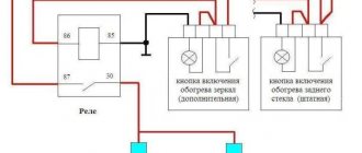
Before you begin installing the emergency lights, you should familiarize yourself with the connection diagram for the Euro button on the VAZ-2114 (2115) , which we will use as an example.
This scheme allows you to avoid the use of relays and interference with standard wiring.
- The connected contacts of the old connector “1” and “3” - to terminal “2” on the emergency button;
- Pin “2” on the button goes to pin “D”;
- Contact “7” – to contact “1” on the button”;
- Pin “B” – to the backlight;
- Conclusions “A” and “C” are mass;
- Pins “8” and “4” in the block of the old connector are bridged.
To replace the hazard warning button we need the following:
- Euro button with a block for it;
- Two 1N4007 diodes;
- Soldering iron;
- Flux LTI-120;
- Screwdriver;
- Two terminals.
Having prepared all the necessary tools, we proceed to replacing the old emergency light using the example of a VAZ-2114 (2115) car and the hazard warning switch 2515 996.3710-07.10 based on the diagram above.
First you need to disassemble the emergency button in the following sequence:- Using a screwdriver, disassemble the steering casing;
- We remove the chip from the old switch and the switch itself from the casing;
- Unscrew the two screws and remove the side panel on the driver's side;
- We extend the freed chip into the window where the on-board computer is usually located;
- We disassemble the old emergency button using a flat screwdriver - it has two grooves, by prying it you can separate it into two parts;
- We keep the block of the old hazard warning connector for ourselves, we can throw away the spring - we won’t need it anymore.
- Then we proceed to connecting new contacts and the switch:
- To obtain a reliable solder, the contact surfaces must first be tinned with LTI-120 acid;
- Contacts “4” and “8” of the chip are immediately connected to each other using wiring;
- To the same chip, to contacts “1” and “3”, we solder two diodes with cathodes to it, and connect the anodes to each other;
- We solder the wires of the new switch from pins “2” and “D” to the free anodes of the diodes;
- In order for the triangular alarm indication icon to flash, we bring the wire of contact “2”, designated in the diagram as “to the dash”, to the instrument panel and connect it to a free contact (do not forget to insert a light bulb into the dash, since it is not provided by the factory);
- We solder the wire going from contact “1” of the emergency button to contact “7” on the chip;
- The remaining contacts of the connected switch “A” and “B” go to ground and backlight, respectively. Take two wire terminals and solder them to pins “A” and “B”. If necessary, this will allow you to remove all the new wires without affecting the old wiring;
- We connect the new wiring harness to the wiring, and connect the free ends of contacts “A” and “B”, to which the terminals were soldered, to the loosely dangling chip on the fog lights.
Connect the ground and backlight, insert the button. All is ready!
VIDEO INSTRUCTIONS » alt=»»>
Note that the bridged contacts “4” and “8” in the block of the old hazard warning switch connector allow you to use the emergency lights even when the ignition is turned off.
This is the only side effect of this connection, but it is insignificant, because no one forces you to turn on the emergency signal when the ignition is turned off.
There is no need to use a relay and, as mentioned above, the button can be disconnected at any time painlessly for factory wiring.
Even a person who is far from such connection diagrams can independently replace the alarm button on a VAZ. Financial costs are minimal, the time for the procedure is a maximum of 30 minutes. Ultimately, your car will have a modern emergency warning system located in a convenient location.
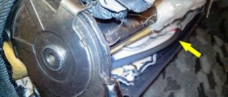
Replacing the column casing
As already mentioned, when removing the old button from the steering column housing, a large hole remains in the latter. Of course, it will not interfere with the operation of the machine, but it is still better to replace the casing.
When choosing a new one (and you will have to select it from other VAZ models), you should consider the following points:
- presence of all necessary holes for control elements;
- their location;
- the size of the hole for the steering wheel (for example, on the casing for Kalina it is very large).
The optimal one, according to the reviews of car enthusiasts themselves, is a standard casing (not “euro”!) for the 10th model.
Scheme for switching on headlights, side lights and turn signals for VAZ-2113, 2114 and 2115
Headlight switching diagram for VAZ-2113, 2114 and 2115
Scheme for switching on headlights and fog lights:
1 – headlights; 2 – mounting block; 3 – headlight switch; 4 – ignition switch; 5 – external lighting switch (fragment); 6 – fog lamps in the internal rear lights; 7 – fog light switch with control lamp; 8 – indicator lamp for high beam headlights in the instrument cluster; K8 – headlight high beam relay; K9 – relay for low beam headlights; A - the order of conditional numbering of plugs in the headlight block; B - to power supplies
Scheme for switching on the side lights of VAZ-2113, 2114 and 2115
External lighting switching diagram:
1 – side light lamps in headlights; 2 – engine compartment lamp; 3 – mounting block; 4 – engine compartment lamp switch; 5 – ignition switch; 6 – external lighting switch (fragment); 7 – indicator lamp for external lighting in the instrument cluster; 8 – side light and brake light lamps in the external rear lights; 9 – license plate lights; 10 – instrument lighting regulator; 11 – brake light switch; 12 – on-board control system unit; K4 – relay for monitoring the health of lamps (contact jumpers are shown inside the relay, which must be installed in the absence of a relay); A - to power supplies;
Materials
1. Electrical tape (preferably blue, as it is especially durable) 2. Four-pin contact turn signal relay from VAZ 2106 3. Connector for relay 4. Six-pin button to turn off/off the alarm 5. Connector for the button 6. Wire for installation and connection the above. Tools: 1. Pliers with wire cutters 2. Flat-head screwdrivers 3. Phillips screwdrivers 4. Open-end wrench 10 5. Knife For those who want to save money at the expense of manufacturability: you can use the original relay from the VAZ 2101, but in this case it will work adequately not guaranteed as this relay is very sensitive to load changes. For this reason, the following installation method involves replacing the relay with a more modern one. Let's get started, unscrew the nut securing the turn signal relay and disconnect three multi-colored wires from it. Next, we determine where to install the hazard warning button. Here we give freedom to our imagination, but a lot also depends on what kind of panel is installed in your car. To the second contact of the relay we connect the wire removed from the contact of the old relay, marked with the letter “L”, and connect all this to the seventh contact of the alarm button. We connect the first contact of the emergency light relay to the fourth contact of the button. We connect the third contact of the relay with the wire removed from the “P” contact of the old relay. We attach the wire coming from the fourth contact of the relay to the car body. The optimal solution would be to secure the wire under the fastening nut of our relay.
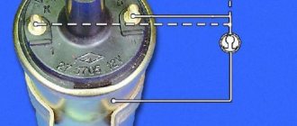
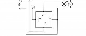
Scheme of emergency lights (hazard warning lights) for VAZ 2101 cars
Now tighten the relay mounting nut with moderate force so as not to break the plastic mount. Then we connect the second contact of the button to the positive wire of the old relay. We connect the first and third contacts of the button to the steering column turn signal switches in any order. The eighth contact of the button is connected to a constant “plus” (independent of the position of the key in the ignition switch). It is advisable to protect this circuit with a fuse. The most suitable would be to install a fuse rated 8A. Next, you should wrap the wires with electrical tape and secure them so that they do not dangle, and install all the previously removed casings and panels. Now we have a full-fledged alarm system and can live a new, full life. The entire procedure for installing an alarm system on a VAZ 2101 takes 2-3 hours.
Lighting devices
7.18.
Scheme for switching on headlights and fog lights: 1 – block headlights; 2 – mounting block; 3 – headlight switch; 4 – ignition switch; 5 – external lighting switch (fragment); 6 – fog lamps in the internal rear lights; 7 – fog light switch with control lamp; 8 – indicator lamp for high beam headlights in the instrument cluster; K8 – headlight high beam relay; K9 – relay for low beam headlights; A - the order of conditional numbering of plugs in the headlight block; B - to power supplies To turn on the headlights, relays of type 90-3747-11 or 904.3747-10 are used, installed in the mounting block. The same relays are used to turn on the sound signal, heated rear window and the electric motor of the engine cooling fan.
The relay switching voltage at a temperature of (23 ±5) °C is no more than 8 V, and the winding resistance is (85 ±8.5) Ohm.
The headlight switching circuit is shown in Figure 7.18. The high and low beam headlights are switched on using auxiliary relays K8 and K9. The control voltage to the relay windings is supplied from the headlight switch 3 if the right button of the external lighting switch 5 is pressed.
Regardless of the position of the switch keys 5, you can briefly turn on the high beam headlights by pulling the headlight switch lever 3 towards you. In this case, voltage is supplied to contact “30” of switch 3 from contact “30” of ignition switch 4.
7.19. Scheme for switching on fog lights: 1 – fog lights; 2 – relay for turning on fog lights; 3 – mounting block; 4 – switch for fog lights with a control lamp (on the left) and a backlight lamp (on the right); 5 – external lighting switch (fragment); A - to power supplies; B - to the instrument lighting regulator
On cars in a variant version, fog lights can be installed in the front bumpers. The diagram for switching on fog lights is shown in Figure 7.19. The headlights are turned on by switch 4 using auxiliary relay 2 type 113.3747-10 installed in the engine compartment on the left mudguard. The fog lights can only be turned on if the exterior lighting is switched on with switch 5.
7.21. Scheme for switching on direction indicators and hazard warning lights: 1 – direction indicator lamps in the headlights; 2 – mounting block; 3 – ignition switch; 4 – alarm switch; 5 – side direction indicators; 6 – direction indicator lamps in the external rear lights; 7 – instrument cluster with turn signal indicator lamps; 8 – direction indicator switch; K2 – relay-interrupter for direction indicators and hazard warning lights; A - to power supplies
The diagram for switching on the direction indicators and hazard warning lights is shown in Figure 7.21. The turn indicators on the right or left side are turned on by switch 8. In emergency mode, switch 4 turns on all turn indicators. The blinking of the lamps is ensured by the relay-breaker K2 in the mounting block.
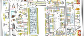
The domestic car VAZ 2114 (Samara-2) is built on the VAZ 21093 platform and is an improved version of it. The interior features a new instrument panel, a new steering wheel, an adjustable steering column, power windows and a new heater. All diagrams are taken from open sources and are intended to help in self-repair of the electrical equipment of this car. Enlarge images by clicking. The VAZ 2114 fuse box is located in the passenger compartment under the dashboard. When checking the electrical circuit of a VAZ-2114 car, you cannot check the serviceability of the circuits for a “spark” - this can lead to burnout of the current-carrying paths of the mounting block.
Recommendations
Comments 50
The other day I installed the same button from VAV-21123. I didn't connect the indicator. The wiring marked “Dimensions” is also not connected anywhere, but the emergency lights are working (all turn signals and repeaters are blinking, the arrows on the dash are blinking, the light in the button is blinking, there is a clicking sound). What is this wiring for (“Dimensions”)?
Then some miracles began. The day before yesterday the following happened several times: arbitrary single clattering of the turn signal while driving (the sound was heard, but I did not notice whether the turn indicator (arrow) was blinking), as well as some kind of grinding noise (as if it was shorting) after turning off the turn signal (had to several times pull the handle back and forth to make it disappear). This happened several times.
Yesterday all this no longer happened, but on one of the turns the car simply passed out - it stalled, but continued to roll. Turned the ignition off and on - it started and drove on. Today this happened again while overtaking, blinking in the other direction. It feels like it was switched off when the turn signal was turned on.
Whether all these events are related to the installation of a new button, or whether it was a coincidence, I don’t know, but it’s disturbing in any case.
>> What is this posting (“Dimensions”) for? In order for the button illumination indicator to glow green when the side lights are turned on)) Most likely a coincidence (I’m talking about a stalled engine). But what is clicking... maybe something is wrong with the relay or the power supply to pin 13 of the relay.
Since then there haven’t been any more such quirks - apparently the button has caught on