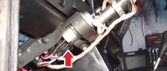
Illumination of the instrument board, how the panel is arranged
Any modern car must have lighting for both the instrument panel and other buttons and switches located on the car’s dashboard. Illumination of the ignition switch is a very common occurrence in imported cars. Our manufacturers have not thought of this, so many drivers improve their iron horse on their own. Such lighting will give your car a special charm at night, and it’s convenient to see where to insert the key.
It is not difficult to install, and its service life is very long. The most important thing is that when choosing such lighting you don’t need to invent anything. Car dealerships, as a rule, sell standard types of backlights that have only one bulb and can only shine at a point. For VAZ cars, they began to produce ready-made elements for illuminating the ignition switch, which are conveniently mounted and do not require alterations or cutouts in the plastic of the car’s steering column.
Pinout of lock VAZ-2108, VAZ-2109, VAZ-21099
Pinout according to the old type
Daewoo Nexia Capricious girl Logbook Unloaded the Nexia ignition switch
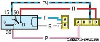
Pinout of the VAZ-2109 ignition switch with unloading relay:
- comes +12V in position I, II, III (parking)
- comes +12V in position I, II, III (parking)
- comes +12V in position III (parking)
- position I, +12V goes out after turning on the ignition (contact 15/2), disappears at start (II);
- position I, +12V goes to the starter (pin 50);
- position I, +12V goes away after turning on the ignition (pin 15), does not disappear when starting II;
- +12V comes from the battery (pin 30);
- comes +12V constantly.
New pinout type
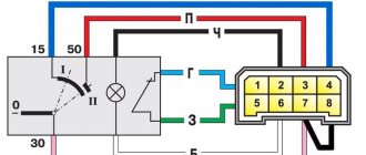
Pinout of the new VAZ-2109 ignition switch:
- comes +12V constantly
- comes +12V constantly
- +12V arrives after turning on the ignition (pin 15), does not disappear when starting II;
- +12V arrives after turning on the ignition (contact 15/2), disappears at start (II);
- position I, +12V goes to the starter (pin 50);
- +12V arrives after turning on the ignition (pin 15), does not disappear when starting II;
- +12V comes from the battery (pin 30);
- comes +12V constantly.
Possible faults
Malfunctions at the lock occur due to the failure of one of the parts. This may be one of the following cases:
- the larva breaks, which manifests itself in wear of the seat of one of the pins, weakening of the springs, etc.;
- the locking rod is damaged or the spring squeezing it out loses its functionality;
- contacts oxidize, become mechanically damaged or burn.
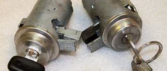
To replace the cylinder, you will need to get rid of the plastic casing and the bolts securing the metal clamp. Included with the new lock are special hardware, which after installation must be torn off the edges with a key.
The current pinout of the VAZ-2101 ignition switch is shown in the picture. It is necessary to observe the sequence of contacts, and also carry out work on the folded battery terminals. Otherwise, a short circuit may occur.
Wiring sequence
When the ignition switch is turned on, the starter does not turn. Why does the starter not respond to turning the ignition key? It also happens
If you are lucky and have a special chip for connecting the lock, everything is simple. But if such an element is missing, then the wiring will have to be connected one by one. To do this, you need to take the terminal block of the inserted lock so that one double-type terminal is located on the right and stands vertically. The top of this terminal should have black wire attached to it.
Next, you should work in the direction of movement of the clock hand. The pink wire will be connected second, followed by blue, brown, and the whole thing will be completed by a red wire. It should be noted that on the rear block of the lock near the terminals there are numbers, each of which corresponds to a specific wire.
Remember that the bottom area of the double view terminal must be left empty. So, the contacts are connected.
VAZ-2105 diagram
Information on the “five” schemes is intended for self-repair of a car in case of minor problems with electrical equipment. The electrical circuits are divided into several blocks (for ease of viewing via a computer or phone), there are files in the form of a single picture with a description of each element - for printing on a printer. Years of production of this model: from 1979 to 2010. At the end of December 2010, AvtoVAZ stopped producing it due to low demand for the VAZ-2105 model. By this time, 2 million cars had already been produced.
Scheme of carburetor VAZ 2105
This is a color diagram of the electrical equipment of the VAZ 2105. At the top of the image on the right are the colors of the wires, at the bottom are the designations of the elements.
1 – block headlights, 2 – side direction indicators, 3 – battery, 4 – starter activation relay, 5 – electro-pneumatic valve for the carburetor forced idle economizer, 6 – starter, 7 – carburetor microswitch, 8 – generator 37.
How does the ignition switch circuit work?
How to remove the cylinder from the Toyota ignition switch. How to remove the cylinder from the ignition switch
The scheme is very simple. The ignition switch has two parts.
- Firstly, the mechanical one, this is the lock itself, which is presented in the form of a cylinder, this is where the key is inserted - an analogue of a crooked key.
- Secondly, the electrical part, which has several contact wires that close when needed after turning the key in different directions.
Without modern anti-theft devices it was more difficult. The only way to protect your car from theft was to remember to take the keys out of the ignition. This meant that the hijackers needed to close the wiring correctly. After which the car could move. It was this circuit that protected the car.
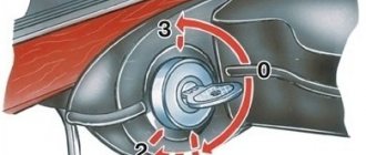
The ignition switch can have four positions. It is how it is located in the system that determines how the car will drive after itself. When all devices are turned off, it means there is no key in the system. In the position numbered one, it is designated as inserting the key into the lock, so you can turn on the radio. Position number two connects all elements that need electricity. In some cars, this position in the form of two levels is sufficient. But there is also, for example, the “start” position, when only the starter is turned on, while no power is supplied to other systems that require a lot of energy.
When the engine is running, you can go back to position “number two” when all systems are working. This way you can look at the time on the display, listen to the radio, see how the backlight worked and other nuances. Their designation is clearly visible on the panel. If the ignition switch is completely turned off, the power will still be supplied. This is possible thanks to the battery. Its core powers some elements of the car. We are talking about side lights, high beams, hazard lights, cigarette lighter, control unit, security system.
To summarize, let's say that the ignition switch has a mechanical and electronic circuit, as well as a whole description of the wires, which are also called a contact. They allow you to start the car by supplying direct current to the volatile elements. If the car does not start, then most likely some contacts have burned out. They need to be found and replaced. A multimeter is used for this. It should show "zero". You can replace the entire group, or you can only replace the damaged wire.
Let's consider. We will talk about using the locking rod
It is also important to use a housing that will allow the ignition to turn on. You still can’t do without a roller, contact disk and bushing
You can also move without pads.
Only after you know how this system circuit works, as well as all kinds of springs and core, can you say that you can replace the lock yourself.
Installing the "Start" button
Some Kopek owners tune the ignition system of their cars by installing a “Start” button instead of the standard ignition switch. But what does such tuning give?
The essence of such modifications is to simplify the process of starting the engine. With a button instead of a lock, the driver does not need to poke the key into the lock, trying to get into the cylinder, especially without the habit and without lighting. In addition, you don’t need to carry the ignition key with you and worry about losing it. But this is not the main thing. The main thing is the opportunity to enjoy the process of starting the engine with one press of a button, and also to surprise the passenger with this.
Using this button, you can start the engine without the ignition switch and key.
In automobile stores you can purchase a kit for starting a power unit from a button for about 1,500–2,000 rubles.
A kit for starting an engine with a button can be purchased at auto stores.
But you can save money and assemble an analogue yourself. To do this, you only need a toggle switch with two positions and a button (not recessed), which will fit the size of the ignition switch housing. The simplest connection diagram is shown in the figure.
The toggle switch and button can be installed in any convenient place
Thus, by turning on the toggle switch, we supply voltage to all devices and to the ignition system. By pressing the button, we start the starter. The toggle switch and the button itself, in principle, can be placed anywhere, as long as it is convenient.
As you can see, there is nothing complicated either in the design of the VAZ 2101 ignition switch or in its repair. If it breaks, you can easily repair or replace it.
The engine start on the domestic “classic” from the Volzhsky Automobile Plant is carried out by turning the key in the ignition switch. This closes the necessary contacts to start the starter. In more modern cars, this option has evolved into remote start from the key fob or start from the Start/Stop button. Drivers who prefer to drive a car that is as close as possible to the factory original tend to restore the original configuration in case of breakdowns.
Lock - ignition
Ignition switch 15 is designed to turn on and off the low voltage current circuit and turn on the starter during engine starting.
The ignition switch is designed to turn on and off the current in the primary winding circuit of the ignition coil.
The ignition switch is installed to prevent an unauthorized person from starting the engine. To do this, it has a special key, which, to prepare the engine for starting, must be inserted into the slot of the lock, pressed and turned to the right, after which the battery current will be closed to the primary winding of the induction coil. When the engine is not running, to turn off the ignition, the key must be turned back and removed from the lock, otherwise unproductive current consumption for heating the wires is inevitable and damage to the induction coil is possible due to overheating of the winding.
The ignition switch is often combined with the light switch in one combination switch (Fig.
The ignition switch device is shown in Fig.
When the ignition switch (starter button) is turned on, the starter armature does not rotate.
When the ignition switch is turned on (the starter button, the drive gear does not engage with the engine flywheel ring.
To the ignition switch terminals, which are closed when the key is turned to the Ignition on position, connect an electrical outlet, preferably a car type, with insulated wires, and secure it in any convenient place, for example, under the instrument panel.
When the ignition key is turned to the Starter position, current from the battery begins to flow through the windings of the starter traction relay. The relay armature is retracted and the relay contacts are closed. At the same time, the relay armature moves the overrunning clutch with the gear through the lever, which, turning with the hub on screw splines, engages with the flywheel ring gear. When transmitting rotation from the starter to the flywheel crown, the rollers are wedged between hub 8 and cage 5, transmitting rotation.
On motorcycles, a combination switch (ignition switch and light switch) is often built into the headlight housing; The low and high beam switch is also built into the headlight and activated by a cable connected to the steering wheel or made in the form of an electric rocker switch mounted on the steering wheel. In this case, it is often combined with an electric horn button (Fig.
Checking the operation and technical condition of the ignition switch, water temperature indicator, oil pressure, fuel level in the tank, sound signal, turn indicators, brake light, lamp, light switches, instrument panel lighting, sidelights and headlights, rear plug socket.
From the positive pole of the battery through the ignition switch, electric current flows into the winding of the bimetallic indicator plate.
The supply voltage of the device is removed from the ignition switch terminals.
| Electrical diagram of the PC950 turn signal switch. |
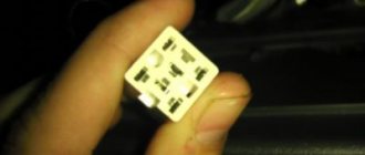
The starter activation relay is designed to relieve the ignition switch contacts from the starter traction relay current.
Underhood wiring
Design features and self-repair of the VAZ 2107 distributor
The electrical circuit of the iconic car is distinguished by simple placement and reliable operation. The wires are connected to the corresponding sensors, devices and components. Connection tightness is ensured by convenient quick-release plug connections.
The entire electrical wiring system can be divided into six bundles of wires:
- front;
- rear;
- right and left;
- clusters of headlights and side turn indicators;
- battery cables;
- instrument panel wires.
A complete replacement of the engine compartment wiring is necessary if there are numerous twists in the old cables
Under-hood wiring includes the front bundle of wires, wires for the turn signals and battery. The main sensors and instruments are located in the engine compartment:
- battery;
- starter;
- generator;
- ignition module;
- high-voltage wires and spark plugs.
Neatly laid wires under the hood speak of the driver’s love for the car.
The thickest wires connecting the car body with the battery and engine serve as the power source for these devices. These wires carry the greatest current when the engine starts. To protect electrical connections from water and dirt, the wires are equipped with rubber tips. To avoid scattering and confusion, all wires are collected into bundles and divided into separate bundles, which are easier to replace if necessary.
Complete replacement of the braid will eliminate loss of tension due to poor contact and numerous twists
The harness is wrapped with adhesive tape and secured to the housing, which prevents individual wires from hanging freely and being caught by moving parts of the power unit. At the location of a specific device or sensor, the harness is divided into independent threads. The harnesses provide a certain order for connecting devices, which is reflected in the electrical diagram.
A detailed diagram allows you to find a section of wires with poor contact
Position numbers of electrical circuit elements on the VAZ 2101 headlight connection diagram:
- Headlight.
- Battery.
- Generator.
- Fuse box.
- Headlight switch.
- Switch.
- Egnition lock.
- High beam indicator.
The latches on the plastic blocks of the plug connectors ensure a reliable connection, preventing accidental loss of contact due to vibration.
Honda Civic ignition switch repair
We often receive requests for ignition switch repairs like the following. In one yard, two attempts to steal a car of the same brand Honda Civic were recorded at once (this happens). The first application was accepted to remove and replace the ignition switch. Upon arriving and examining the lock, our auto electrician discovered minor damage to the lock itself, as well as to the driver's door. It was clear that there had been an attempted theft. The original key was not inserted into the lock, and the owner decided to replace it. After removing and examining the lock, he told the owner that it was possible to repair and restore the functionality of the ignition switch. And, having weighed all the pros and cons, he agreed to the repair, since replacing the lock means, first of all, a long wait for the ordered lock itself, transporting the car to the dealership, re-chiping the key, replacing the door and trunk cylinders, and, naturally, a big waste of money. The repair and installation of the ignition switch was completed within one day. High-quality repair of the ignition switch cost the owner faster, and much cheaper than if he had contacted the dealership to replace the ignition switch, considering that they simply do not deal with such trifles as repairing the ignition switch. The next day, a similar application for a similar brand with a similar problem was received from the same yard. Arriving at the scene, the auto electrician saw the same situation with another Honda Civic, standing at the next entrance. Filmed like a carbon copy. The same damage and the same error. Inability to bypass the standard immobilizer. The owner, already familiar with the neighbor’s experience, asked to repair the ignition switch. The castle was completely renovated, saving the owner money and time. We successfully carry out repairs of a wide variety of brands and models of cars, including repair of the ignition switch 2112, Honda civic 4d, vw caddy, w164, Audi, BMW, VAZ 2106, VAZ 2109, VAZ 2110, VAZ 2115, Granta, Daewoo Nexia, Kalina , Kia Rio, Kia Sid, Kia Sid 2008, Lancer 9, Mercedes, Mercedes 124, Mercedes 210, Mercedes w212, Mitsubishi Lancer 9, Mitsubishi L200, Mitsubishi RVR, Niva Chevrolet, Opel Astra H, Opel Vectra A, Passat B3, Peugeot 307, Priora, Renault, Renault Logan, Sum Orbit 50, Toyota, Fiat Albea, Fiat Ducato, Volkswagen Polo sedan, Ford Focus 1, Ford Focus 2, Hyundai Getz, Honda, Honda Accord 7, Honda Odyssey 1998, Honda SRV, Honda SRV 3rd generation, Honda Fit, Honda Civic 4D, Hyundai Re, Skoda Octavia A5.
How to connect a new ignition switch instructions
The set of necessary tools is minimal - you only need a Phillips screwdriver and a small slotted screwdriver.
Work order:
- All work related to repairing or replacing electrical equipment in a car must be carried out with the battery disconnected. Connecting the ignition switch is no exception to this rule, so first turn off the engine and disconnect the power cable from the negative terminal of the battery.
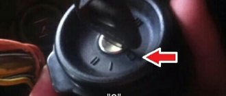
- Set the key in the ignition switch to position “0”, that is, so that its head is in a horizontal position.
- Remove the five screws securing the two parts of the plastic casing that hides the steering shaft underneath. Separate these parts and remove them.
- There are two screws holding the ignition switch in place - find and unscrew them.
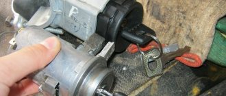
- Using a small slotted screwdriver, press the latch that holds the ignition switch in place and pull the lock toward you.
- Following the lock, wires coming from the common wiring harness of the instrument panel will also follow. All these wires connected to the ignition switch must be collected in a single adapter block - motorists often call it a chip.
- If the chip is in its proper place, connecting the new ignition switch will be very easy, you just need to simply disconnect the chip and attach it to the new ignition switch in the only possible way. In this case, you don’t have to read points 8, 9 and 10, since for you the work of connecting a new lock is almost complete.
- If for some reason the block is missing and the wires are connected to the ignition switch directly, each in its own socket, then before disconnecting the wires, be sure to draw a diagram of their connection to the lock contacts. To do this, sketch out the location of the contact plates in the lock on a piece of paper and mark what color wire fits each of them - for ease of connection, all wires have a braid of different colors. After drawing up the diagram, disconnect the wires from the ignition switch terminals.
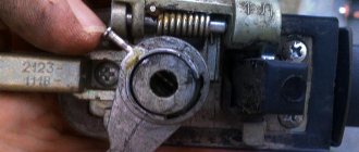
- The situation is even worse if you have to change the ignition switch in your car after an unsuccessful attempt to steal it by thieves who tried to start the car without a key, directly by tearing out the wires from the ignition switch. In this case, in order to connect the wires correctly, use the following hint: on the back of the ignition switch there are small print marks for all terminals. Each terminal corresponds to a wire of a certain color:
- terminal 15 – blue wire with a black stripe;
- terminal 30/1 – brown wire;
- terminal 50 – red wire;
- terminal 30 – pink wire;
- terminal "INT" - black wire.
Connect all wires in the correct order to the terminals of the new ignition switch. A little advice: in order not to do all this extra work in the future, buy a plastic block in the store - the trick that was described earlier. In the manner described above, connect the wires to it, and not to the lock itself, and connect this entire connector assembly directly to the new ignition switch.
Once the wires are properly connected, install the new lock in place, secure it with screws, and reassemble the plastic steering column cover. Then connect the battery and test the operation of the new ignition switch.
To ensure that the new lock works properly in the future, start the car correctly. How to do this is described in our article How to start a car correctly.
Find articles on the procedure for carrying out other repair work on our website in the Car Repair section.
Wiring harness in the cabin
The front wiring harness, located in the engine compartment, is the main electrical system. The front beam enters the car interior through a technological hole with a seal under the instrument panel. The front end electrical system connects to the dash wires, fuse box, switches, and ignition. In this part of the cabin, the main electrical circuits are protected by fuses.
The new cable will provide sufficient voltage to power current consumers in the cabin
The fuse box is located to the left of the steering wheel. Auxiliary relays are attached to the bracket behind the block. The reliable operation of the VAZ 2101 depends on the proper functioning of electrical devices and relays. Fuses protect the electrical circuits of the VAZ 2101 from short circuits.
Simple fuses are a reliable safety element in the event of a short circuit
List of electrical components protected by fuses:
- Horn, brake lights, interior lamps, cigarette lighter, portable lamp socket (16 A).
- Heating motor, wiper relay, windshield washer motor (8 A).
- Main beam of the left headlight, high beam indicator lamp (8 A).
- High beam of the right headlight (8 A).
- Low beam left headlight (8 A).
- Low beam of the right headlight (8 A).
- Side light of the left sidelight, side light of the right rear light, size indicator lamp, instrument panel light, license plate light, trunk light (8 A).
- Side light of the right side light, side light of the left rear light, cigarette lighter lamp, engine compartment light (8 A).
- Coolant temperature sensor, fuel level sensor and reserve indicator lamp, oil pressure lamp, parking brake lamp and brake fluid level indicator, battery charge level lamp, direction indicators and their indicator lamp, reversing lamp, glove compartment lamp ) (8 A).
- Generator (excitation winding), voltage regulator (8 A).
Video: replacing an old VAZ 2101 fuse box with a modern analogue
Switching of instruments in the cabin is made with low-voltage wires with elastic oil- and gasoline-resistant insulation. To facilitate troubleshooting, the wire insulation is made in different colors. For greater distinction, spiral and longitudinal strips are applied to the insulation surface to eliminate the presence of two wires of the same color in the bundles.
On the steering column there are contacts for switches for the direction indicator, low and high beam, and sound signal. In the assembly shop, the contacts of these switches are lubricated with a special conductive grease, which must not be removed during repairs. Lubrication reduces friction and prevents oxidation of contacts and possible sparking.
If the order of connecting elements is violated, traffic participants may be misinformed
Position numbers of electrical circuit elements on the turn signal connection diagram:
- Sidelights.
- Side direction indicators.
- Battery.
- Generator.
- Egnition lock.
- Fuse box.
- Relay interrupter.
- Power indicator.
- Switch.
- Rear lights.
The intermittent signal of the turn signals is determined by the breaker relay. The ground connection is provided by black wires, the positive connection is provided by pink or orange wires. Inside the car, the wires are connected:
- instrument panel and indicator lights;
- headlight clusters;
- direction indicators;
- interior lighting;
- wiper;
- foot-operated windshield washer.
The rear wiring harness runs along the left side of the cabin under the floor mats. A thread runs from it to the light switch in the door pillar and the parking brake lamp switch. The branch to the right lamp runs behind the rear beam along the floor of the body, where the wires connecting the level indicator and fuel reserve sensor are located. The wires in the bundle are secured to the floor with adhesive tape.
The procedure for connecting wires to the ignition switch
Let's consider all stages of work one by one. First, remove the casing from the top and bottom of the steering column. Now, using a marker or regular paint, we mark the wires connected to the rear lock, after which they can be carefully disconnected.
Using a cross-head screwdriver, unscrew a pair of screws located below and directly securing the locking device:
Now we insert the key and turn it to the zero position to disable the anti-theft device that blocks the steering. At the same time, use a thin awl or a screwdriver to press on the fixing element, with the help of which the lock is held in place:
After completing these steps, pull the key to remove the locking mechanism from the bracket:
To install a new lock, all operations should be performed in reverse order.
Post navigation
Accordingly, the key closes the contact elements of the electrical circuit, helping to start the power unit of the machine. This refers to the windshield wiper system, washer motor, generator unit, heater fan, control panel devices, turning lights, ignition system, sound devices. It's easier to buy a new group in the store. The two parts of the lock are connected to each other by means of a leash.
There is a flat slot on it; you need to insert an awl or a prepared nail there.
Conclusion When replacing this element, you should be very careful, since if it is connected incorrectly, the entire ignition circuit will stop working and you will not be able to start the engine.
But, if, nevertheless, a replacement is necessary, then let's figure out how to do it correctly. We suggest the following sequence of actions that will help you easily connect the ignition switch to a VAZ: Insert the key and turn it to the zero position. The secret itself is not repairable, and in the event of such a malfunction, the VAZ ignition switch will eventually need to be replaced
Disassembly consists of the following steps: Turn the lock with the back side facing you and remove the retaining ring, prying it off with a flat-head screwdriver.
On the driver's side, the mechanism has a key hole. Repair LuAZ 969/ Ignition switch LuAZ 969 M, wire in the lock - how to connect correctly
Replacing the ignition switch
To solve all these problems, the surest solution is to replace the ignition switch. Many motorists are in no hurry to immediately contact a car service center, but try to repair their beloved child with their own hands. Is it possible to replace the lock yourself without having special abilities and skills? Yes, this is quite possible, and any real man can do it.
Wiring ringing
So, depending on the cause of the malfunction, replacement may be:
- Complete lock replacement
- Replacing the lock cylinder
- Replacing the contact group.
You can check the serviceability of the contact group without removing the ignition switch. To do this, you will need a multimeter, ohmmeter or any other device for testing wires. The contact resistance must be zero, otherwise they are faulty. And then it is necessary to replace the contact group of the ignition switch.
Dismantling the lock
To partially or completely replace the ignition switch, it must be removed. To do this, we may need a minimal set of tools.
The ignition switch on all classic VAZ car models is located below, on the left of the steering column. So, our actions:
Disconnect the battery to de-energize the ignition switch.
Unscrew the screws securing the plastic casing and remove it. Unscrew the pair of screws that secure the ignition switch to the bracket.
Disable the anti-theft device. To do this, insert the key and turn it to position zero. Using an awl, press the latch and remove the lock.
In the “classic” models (2101-2107), the wires are connected to the ignition switch not using a solid chip, but each separately. Therefore, before removing the lock, when disconnecting its contact group, it is advisable to use markings to mark the correspondence of each wire to the number of the contact to which it is connected. Otherwise, you may get them mixed up when you put the lock in place.
Let's disassemble the castle itself
Once you have the lock in your hands, you can replace its faulty part or replace it with another working ignition switch. If you replace the contact part, you will need to find the retaining ring - it is located at the bottom of the lock - and remove it (you can do this with an awl or a thin screwdriver). Then, after installing the working part, return it to its place. Before installing the aftermarket ignition switch, turn the key inserted into it to position “I” so that the latch that blocks the steering shaft is pushed into the lock body.
It is done. Now, using the previously marked markers, we attach the new contact part of the lock in the same way as the previous one was attached.
We tighten the screws securing the lock, fixing it, put the decorative casing in place - and the dismantling is complete! You can now turn on the engine to ensure that all contacts are active and the job is successful.
Later VAZ models
If we consider later VAZ models, then their ignition switch is mounted on the right side of the steering column using a bracket clamped with mounting bolts. The most difficult thing in dismantling a lock is unscrewing the bolts, which are made specifically in such a way as to complicate the task of removing the lock, thereby reducing the likelihood of hacking. To overcome this difficulty, it is recommended to use a chisel and pliers. Using a chisel, carefully loosen the bolts, being careful not to damage their heads.
Then we unscrew them with pliers. When all four bolts are unscrewed, remove the clamp and, accordingly, the lock. The repaired or replaced lock is reattached with four break-away bolts, which are disposable to prevent tampering.
Difficulties may also arise if your immobilizer is activated (an anti-theft device that is equipped with new VAZ cars). This problem is mainly electrical, so to solve it, you may have to use the help of an auto electrician to help you recode the immobilizer. If it is turned off and a regular alarm system is installed on the machine, then no difficulties should arise during the dismantling process.
If, after completing all the steps to replace the lock, you were unable to start the car, or the car started and stalled, it means that an error was made in the process, which you can correct yourself, or seek help from specialists. With a little ingenuity and patience, you can do minor repairs yourself. Good luck.
Removing and installing the lock
Removing this element from the car is quite simple and all you need is a Phillips screwdriver and a thin flat-head screwdriver or an awl. Before starting work, be sure to disconnect the negative terminal from the battery.
To get to the fastening of this element, you will first need to unscrew the bolts securing the lower facing panel of the steering column, and then remove it.
Removing the ignition switch
Afterwards, you need to unscrew the two bolts securing the lock, which hold it in its seat. In the same seat there is a small technological hole. By inserting a thin screwdriver into this hole, you need to press the latch that holds the lock, and then push it out of its seat.
Only then disconnect all the wires. On some models, the wiring going to the lock is collected in a chip that is put on the contacts of the lock. This feature will greatly facilitate the installation of a new element, since such a VAZ-2101 ignition switch does not require a wiring diagram.
How to remove the lock
| Remove the two screws securing the ignition switch (bottom view). | Insert the key into the ignition switch, turn it to position “0” (turning off the anti-theft device), press the lock with a screwdriver through the hole in the bracket and... |
| ...remove the switch from the bracket and the key from the switch. | Label (or remember the connection order) the wires and terminals of the ignition switch. Disconnect the wires from the switch. |
But there are also versions of the car in which the wiring is directly connected to the contacts, and when installing a new element with this type of wiring connection on a VAZ-2101, an ignition switch circuit will be required.
If the lock assembly is replaced, then you can connect the wiring to the new one, install it in place, secure it and cover it with a decorative panel.
If only the contact group is changed, then the removed lock is disassembled. The contact group is fixed using a locking ring, which must be pryed off with an awl or screwdriver and removed. After this you can remove the group. A new one is installed in its place and secured with the same retaining ring. After this, everything is put in place and the VAZ-2101 ignition switch is connected.
Reasons for replacement
Many problems associated with the ignition switch can be eliminated by replacing only individual parts, and not the entire switch as a whole. You can buy a contact group or a lock cylinder separately. That is why repairs should begin with high-quality diagnostics. Main malfunctions and their symptoms:
- The starter does not respond to turning the key. The reason is most likely in the contact group. To verify this, check whether power is supplied to the starter relay after turning the key to the On position (starter activation mode). If the relay clicks, it means that the system “sees” the key being turned and there can be no complaints about the components of the electrical circuit of the lock. On vehicles that are not designed to have a starter relay, the power should be checked at the corresponding terminal of the solenoid relay. For diagnostics, you can use a multimeter or a tester (one lead to ground, the other to the retractor contact coming from the ignition switch). If the retractor and wiring are in good condition, then the contact group has failed;
- the key moves with a wedge. The problem is in the lock cylinder, as over time the mechanism wears out and becomes clogged. In this case, aerosol lubricants can only temporarily eliminate the malfunction;
- The key does not turn to all positions. The reason is mechanical damage to the lock cylinder. It may also be due to jamming of the anti-theft locking mechanism of the steering shaft;
- the key turns, but power does not come to the corresponding groups of contacts. The reason is in the contact group. The pinout of your vehicle's ignition switch can be found in the repair and maintenance manual.
Features of the VAZ-2101 electrical circuit
For the VAZ-2101 there is also a standard electrical diagram compiled by specialists from the manufacturer of this car. Its main features are as follows:
- The DC electrical circuit is single-wire.
- The direct current connection is carried out from the “ground” to the “minus” terminal of the current source (on the VAZ-2101 such a conductive line “ground - minus” is the entire body, that is, all devices that consume electricity are connected by one wire to the “ground”-body) .
- The DC source is a battery with the following characteristics:
- brand – 6-ST-55 EM;
- voltage – 12 V.
- Alternator with the following characteristics:
- brand – G221;
- power – 500 W;
- the presence of selenium rectifiers (they are built into the back cover of this device);
- rated current – 42 A;
- maximum current at permissible load – 53 A (at 5,000 rpm);
- voltage – 14.5 V.
- Voltage regulator with the following characteristics:
- brand PP380;
- automatic adjustment (two-stage type).
- Battery with the following characteristics:
- capacity – 55 Ah;
- discharge mode – 20 hours.
All of the listed elements are connected to the VAZ-2101 using a parallel type.
For the VAZ-2101, a circuit of fuses has also been developed, which are needed to prevent a short circuit in the electrical circuit in a certain closed section (it is this that is sketched on the electrical circuit). For convenience and quick search for a failed fuse, the entire graphic diagram is divided into ten parts. This is exactly the number of fuses used on the VAZ-2101. They are also marked in different colors and numbered according to the actual data.
If one of the elements of the vehicle's electrical wiring is in poor condition, it will require immediate replacement. In this case, you cannot do without knowledge of the electrical circuit.
https://youtube.com/watch?v=CykyUv0BPY0
Replacing the contact group of the VAZ ignition switch
- Replacing the ignition lock cylinder
- When is it necessary to replace the ignition switch cylinder?
- Materials for replacing the ignition lock cylinder
- How to replace the ignition switch cylinder yourself?
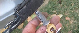
Worn parts (namely pins) of the cylinder in combination with the wear of the ignition key are quite often the cause of a jammed ignition switch. If for a domestic car it is easier/cheaper to replace the ignition switch assembly, then with a foreign-made car everything is somewhat more complicated - the cost of the ignition switch is steep, and there is not much chance that the ignition switch will be available.
Buying a used lock is also not a great solution - the lock has worked for about the same amount of time as yours, and the chances that it will last much longer are not very many. Not always, but in most cases the solution to the problem is to replace the ignition switch cylinder. As a rule, the larva does the bulk of the work in the lock, and, accordingly, also wears out the fastest.
Is it necessary to remove the ignition switch to replace the cylinder? Usually, replacing the cylinder does not require dismantling the ignition switch.
However, on some car models (for example, the Mercedes family, the ignition switches of Mercedes cars have fairly good protection against hacking, there is no way to do without removing the lock) it is not possible to replace the ignition switch cylinder without dismantling the lock.
When is it necessary to replace the ignition switch cylinder?
1. Attempted theft by breaking the ignition switch.
2. Loss of all duplicate keys.
3. Failure of the contact group.
4. Due to the poor quality of the metal, grinding of the internal elements occurred, so the key does not cause the pins to move.
5. The key broke right inside the lock, and it is impossible to remove it.
6. Poor contact in the lock prevents the engine from starting normally.
— cylinder complete with new keys;
- thin watch screwdriver;
How to replace the ignition switch cylinder yourself?
1. Disconnect the negative cable terminal from the battery. Remove the screws connecting the steering column housings. Two of them are located near the steering wheel and two are located near the instrument panel.
2. Unscrew the screws securing the lower and upper steering column casing. Remove the covers. The ignition switch lock is accessible. In principle, the lock cylinder can be obtained already at this stage. To do this, pull out the side pin that holds it in the lock. This can be done with a thin watch screwdriver and tapping it with a small hammer. If the pin does not come out, try carefully drilling out the cylinder with a thin drill.
3. If you decide to remove the ignition switch before changing the cylinder, then to do this, first unscrew the bolts securing the ignition switch. This must be done with a hammer and chisel, since their heads are cut off. Loosen them slightly and then unscrew them with pliers. Remove the bracket and ignition switch from the steering column, disconnect the electrical connector.
4. Unscrew the self-tapping screw securing the ignition relay, remove it from under the panel and disconnect the connector. Disconnect the relay ground wire. Using a Phillips screwdriver, unscrew the self-tapping screw, press out the latch, remove the cover and contact group. So you've removed the ignition switch.
5. Remove the cylinder from the ignition switch lock as described in point 2. Replace it. Check the operation of the lock with a new cylinder by turning the ignition key. Install the ignition switch by performing all steps in reverse order. Replace the steering column. Don't forget to connect the terminal to the battery. Check the operation of the ignition switch and other electrical equipment of the vehicle.
Electronic ignition device VAZ 2106
As well as homemade versions of the electronic ignition circuit VAZ 1 ignition system - generator; 3 — ignition distributor; 2 — ignition switch; 5 — spark plugs; 4 — breaker cam; 6 — ignition coil; 7 - 12 volt battery Scheme of the classic contact ignition system KSZ for various VAZ models 1 - spark plugs; 2 - distributor; 3 - capacitor; 4 — breaker cam; 5 - coil; 6 — mounting block; 7 - relay; 8 - switch; A - to terminal “30” of the generator Scheme of the contactless ignition system BSZ VAZ 1 - spark plugs; 2 — sensor-distributor; 3 — screen; 4 — non-contact sensor; 5 - switch; 6 — ignition coil; 7 — mounting block; 8 - relay; 9 - switch; A - to the thirtieth terminal of the generator. In this case, you need to tighten the contacts and clean the terminals from oxidation. A thin-section secondary type wire winding containing up to 30 turns is placed on the core, designed to increase the electrical potential. If the wires are normal, then the marks are not aligned. If the engine volume is 1.5 liters, then this part is missing and this step is skipped. As for the VAZ injector ignition coil, a distributor-breaker is not used in engines of this type. Then a short-term pulse of up to 24 thousand is formed in the secondary. By this we will exclude the remaining elements of the ignition system and we will be sure that it is the ignition module that is faulty. The price of a new such part is about rubles, or even a little cheaper. The connection diagram of several elements is as follows.
Selecting an ignition coil for VAZ 2106
Otherwise, the module must be replaced. Next, a spark is formed at the electrode of this spark plug, igniting the fuel-air mixture. Achieve the most stable operation of the motor and tighten the nut. Ignition distributor sensor: Contactless distributor type
The cable with connectors is used for reliable connection of the terminals of the ignition distributor and the switch. The 1.5 liter VAZ valve injection engine used the same non-contact ignition system as the 8-valve engine, but a different ignition module was installed. In ohmmeter mode, install one multimeter probe on the central terminal, the second on the metal body.
Remove the central high voltage wire from the distributor cover clamp and set the gap mm. The network voltage is tested by a special controller. Drill and attach the commutator next to the coil. Also disconnect all power wires from the coil contacts. The high voltage output is connected to another contact of the secondary winding and a high voltage wire contact leading to the breaker distribution element, which, with the rotational movement of the slider, distributes the high voltage current to the spark plugs. UAZOBAZA # 73 Continuing the topic of ignition for UAZs - ignition coils