Purpose and principle of operation of the DPRV
The position sensor is designed to determine at a specific moment in time the position angle of the timing shaft. The obtained indicators are sent to the control unit, and after their processing, the operation of the automobile engine is adjusted to increase the efficiency and completeness of combustion of the combustible mixture. The result of the device is an increase in vehicle power, economic indicators and improvement of other characteristics.
DPRVs differ not only depending on the make and model of the car, but for different engines, for example, for eight- and sixteen-valve internal combustion engines.
To get an answer to the question of where the camshaft sensor (phase sensor) is located on a VAZ 2112 16 valves, just open the hood and carefully examine the internal combustion engine - it is located in the area of the timing shaft.
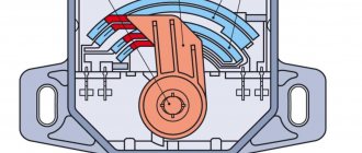
A rotor made of ferromagnetic material rotates together with the camshaft. Between the rotor and the permanent magnet is a Hall IC. When the protrusion passes by the DPRV element, the level of magnetic field strength changes, a voltage of a certain strength is induced and a signal is created, which is sent to the ECU for subsequent analysis.
What does code P0340 mean?
Depending on engine speed and load, the engine control unit controls the timing and quantity of fuel injection, ignition timing, and in the case of engines with variable valve timing (VVT), adjusts the intake and exhaust valves.
The two main timing and position sensors used by the ECU are the crankshaft position sensor (CPS) and the camshaft position sensor (CSP). If a VVT equipped engine has two cylinder banks, there will be two camshaft position sensors.
The DPRV reacts to the gear on the camshaft, providing the ECU with constant information about its speed and position. Of course, the sensor is located on the engine, usually somewhere on the cylinder head, so it transmits data using wires.
If the ECU detects an interruption in the CVS signal, it will set a code P0340 or P0345 - Camshaft Position Sensor Circuit Malfunction.
- Trouble Code P0340 – Camshaft Position Sensor A Circuit Malfunction (Bank 1)
If your engine only has one VCR (four-cylinder engine), then the only code available is P0340.
On the other hand, a V6 or V8 engine has two banks, Bank 1 and Bank 2, and will therefore have two VDPs, so the P0345 code will refer to Bank 2.
Sensor A indicates that a malfunction occurs in the camshaft position sensor circuit, which relates to the intake camshaft. Sensor B codes refer to the exhaust camshaft.
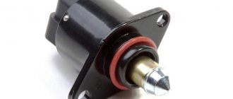
What is a phase sensor?
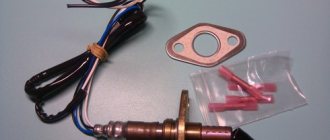
Appearance of the phase sensor from a VAZ-2112 car
The value of the phase sensor speaks for itself. So, he is responsible for the correct operation of the cylinder phases.
This is the only sensor in the internal combustion engine, which, if it breaks down, causes the engine to stop completely and it is no longer possible to get to the garage or parking lot.
Featured Posts
Hello. Help me to understand. Delivered January 5.1 261. 3763 00-01
112298 ___- 41 ELKARovsky, date of issue 09.18.2009. firmware a5_05n35
If the camshaft timing sensor is working properly, it comes out at 2000 rpm.
error, P0340 incorrect signal from the RV phase sensor. Engine 2112 at 2000 rpm. troit,
The failure during acceleration is very noticeable. Phased injection switches to parallel in pairs, with a decrease in 2000 rpm. work is being restored.
Replacing the RV phase sensor and firmware for 41 did not give any results. With another BU M 1.5.4N everything works OK. I checked the marks on the pulleys.
Hello.
Help me to understand. Delivered January 5.1 261. 3763 00-01 112298 ___- 41 ELKARovsky, release date 09/18/2009. firmware a5_05n35If the camshaft timing sensor is working properly, it comes out at 2000 rpm.
error, P0340 incorrect signal from the RV phase sensor. Engine 2112 at 2000 rpm. troit,
The failure during acceleration is very noticeable. Phased injection switches to parallel in pairs, with a decrease in 2000 rpm. work is being restored.
Replacing the RV phase sensor and firmware for 41 did not give any results. With another BU M 1.5.4N everything works OK. I checked the marks on the pulleys.
make an indicator on an LED, connect it to the df signal pin and watch the signal at the rpm.
If the signal disappears, then the phase sensor is at fault. Well, if there are impulses, then the block “plants” the signal.
Look at the sensor's power supply!
If the signal disappears, then the phase sensor is at fault. Well, if there are impulses, then the block “plants” the signal.
Look at the sensor's power supply!
Thank you for the hint.
There are pulses from the sensor throughout the entire speed range, it looks like the unit is “planting” the signal.
There is power to the sensor.
Can you tell me what way out in this case there is, other than redoing it on....61st. The store doesn't want to accept it under warranty. They say prove that the unit is faulty, they don’t take your word for it.
I don’t really want to give up phased injection.
I had the same nonsense, I also checked everything and didn’t fix it, then I spat on everything and turned it off in the firmware and I’m happy. CONSUMPTION IS LESS IN THE CITY THERE IS 6.8-7.5 AT THE SAME TIME I PRESSURE ON THE SLIDER UP TO 5000 REV THE ROAD IS 4.8-5.2 AT 100-120 KPH on diagnostics, the injection time dropped to 1.9-2.0 ms, this is all without DF, that is, with pairwise parallel injection
Well, if you don’t want to switch to pairwise parallel injection, then in the firmware uncheck the flag for PHASE SENSOR ERROR and phased injection will work
I had the same nonsense, I also checked everything and didn’t fix it, then I spat on everything and turned it off in the firmware and I’m happy. CONSUMPTION IS LESS IN THE CITY THERE IS 6.8-7.5 AT THE SAME TIME I PRESSURE ON THE SLIDER UP TO 5000 REV THE ROAD IS 4.8-5.2 AT 100-120 KPH on diagnostics, the injection time dropped to 1.9-2.0 ms, this is all without DF, that is, with pairwise parallel injection.
Well, if you don’t want to switch to pairwise parallel injection, then in the firmware uncheck the flag for PHASE SENSOR ERROR and phased injection will work
Yes, I’m getting closer to the idea of throwing out the RV phase sensor. Is it necessary to disable the sensor in the firmware? According to the idea, the block itself should react and divide the injection in half. And pay off the check with a tick. During acceleration and at 1850 rpm, the engine shakes terribly. And if the flow rate and dynamics do not disappear, remove the sensor, of course the solution.
Yes, I’m getting closer to the idea of throwing out the RV phase sensor. Is it necessary to disable the sensor in the firmware? According to the idea, the block itself should react and divide the injection in half. And pay off the check with a tick. During acceleration and at 1850 rpm, the engine shakes terribly. And if the flow rate and dynamics do not disappear, of course remove the output.
At first it won’t run very well, but after adapting to the mixtures it will be restored to factory parameters - before removing the terminal from the battery.
micljevsergey , so it’s easier to change it by flashing good ones.
At first it won’t run very well , but after adapting
to the mixtures it will be restored to factory parameters - before removing the terminal from the battery.
Let it be to you.., what other adaptations for DF in I 5.1? It will simply automatically switch to pairwise-parallel, and that’s it..
Let it be to you.., what other adaptations for DF in I 5.1? It will simply automatically switch to pairwise-parallel, and that’s it..
there are no phase sensor adaptations. After switching to partial injection, the engine will need to adjust the mixtures to this mode. The calibrations include -add. injection time in pp mode. Perhaps because of this coefficient, adjustment is needed.
Is everything somehow limited to the LED? Normal diagnosis!
During acceleration and at 1850 rpm, the engine shakes terribly.
Is this true both with and without a sensor?
I propose a more complex diagnosis. Oscilloscope, open block and consistently look where the DPRV goes at speed. I believe that the low signal level is being licked. When there is no zero. Sometimes it is enough to load the sensor itself with a resistor to ground and everything returns to normal. OR in the block, the very first comparator processing the signal has a failed lower key. Either replace the m/sx, or use the same resistor to ground. I repeat, you cannot check with an LED, only with an oscillation.
Were the signals from DPKV and DPRV simultaneously viewed by an oscil? Is the signal from DPRV not “delayed”?
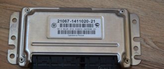
Camshaft sensor (phases) VAZ-2112 16-valve. (SOATE) 2112-3706040-01
Both RRP prices (recommended retail price) or the one indicated below are available for ordering.
| Internal code | 12171 |
| vendor code | 2112-3706040-01 |
| Brand | SOATE |
| Type | Camshaft phase sensors |
| car brand | Lada(VAZ) |
Characteristics Camshaft sensor (phases) VAZ-2112 16-valve. (SOATE) 2112-3706040-01
| Express delivery | from 300 rub. * | from 1 day * | Buy with delivery |
Your review will be published after being moderated
Thank you for your attention to the project. Together we will make dvizhkom.rf better. After correcting the inaccuracies, we will send you an email telling you about the changes.
Unfortunately, now you can order more if you call us at 8-800-775-7556
The quantity to order an item must be a multiple of
We have sent you a password to the specified email address. You can change your password or other registration data in your personal account settings
Hereby, in accordance with Federal Law No. 152-FZ “On Personal Data” dated July 27, 2006, you confirm your consent to the processing of personal data by RAT LLC: collection, systematization, accumulation, storage, clarification (updating, changing), use, transfer solely for the purpose of fulfilling your order and informing about it, as well as promotions and campaigns of RAT LLC, including blocking, depersonalization, destruction. We, RAT LLC, guarantee the confidentiality of the information we receive. The processing of personal data is carried out for the purpose of effective execution of orders, contracts and other obligations accepted by RAT LLC as binding on you.
This consent applies to the following personal data: last name, first name and patronymic, email address, postal address for delivery of orders, contact phone number, payment details.
How does it work
This mechanism works quite simply. At the same time, his role in the whole process is very large. Therefore, it is necessary to monitor the serviceability of the sensor. It forms a pulse that is sent to the electronic unit. As a result, the motor is controlled. At the same time, the amount of gasoline supplied and the opening and closing of the exhaust valves are strictly controlled.
The phase sensor allows you to set the motor operating cycles as accurately as possible. Clearly determines what kind of impulse has been formed and how well it meets the requirements. Install this device next to the cylinder head. The latter is located on the engine where the air filter is located.
Signs of DPRV failure
Over time, the phase sensor on the VAZ stops functioning correctly. Natural wear and tear is the main, but not the only reason for device failure. Signs of malfunction are easy to identify. It is enough to pay attention to how the car engine works. The first start of the internal combustion engine will be difficult and, instead of the usual “grabbing”, it will occur after a long period of torsion of the starter. During the operation of the vehicle, its power noticeably decreases, during acceleration “dips” in dynamics are observed, and instability in engine operation is periodically felt. In addition, motor fuel consumption increases significantly. This happens because the “electronic brain” issues commands for the fuel supply system and the moment of its ignition, based on incomplete data, thereby fuel injection is carried out under non-ideal operating conditions. Also, the “SNACK” signal will light up on the dashboard, which indicates the need to conduct a computer check of the vehicle systems. On some vehicles it is possible to lock the gearbox in one position.
These symptoms indicate problems that have arisen in the operation of the internal combustion engine, and the need for urgent comprehensive diagnostics to identify the exact cause of their occurrence.
When diagnosing a car with a computer, a phase sensor error will be indicated by one of the following codes stored in memory: P0300, P0340, P0341, P0342, P0343, P0344, P0365.
How to understand when replacement is needed
VAZ-2112 engines 16 valves: characteristics, 124 and 2112
There are several main symptoms that allow you to recognize a malfunction in the sensor:
- The Check Engine light came on on the dashboard. Often such problems are accompanied by the number 24.
- The engine stalls while driving.
- Information from the speedometer is transmitted in jerks or waves.
- The odometer stops working.
Where to look for a speed sensor
Replacement is needed if after checking it becomes clear that the cause of the malfunction is in the sensor. Photo: mymechanic.ru
The sequence of work will be as follows:
- We take a set with keys and equipment.
A new speed sensor can be purchased for a minimum cost of two hundred rubles. You cannot do without a good and high-quality sealant.
The hood of the car opens and the required device is located under it. Usually it is located somewhere in the center. Just look behind the power unit. Next you need to find the power connector. It comes with a harness of wires that are also connected to the sensor. All that remains is to disconnect the connector itself. To do this, you just need to press on the special “antennae”. Then we need to unscrew the speedometer itself. In this case, you do not need to use any keys. You need to start rotating the device itself manually, in a direction that goes in the opposite direction from the normal movement of the hand on the clock. The key can be used if the device is stuck in place too tightly. It is recommended to remove the old sensor and immediately inspect the surface for obvious defects. You can safely throw it away if the fault is confirmed. Next comes the installation of the new device, its connection to the wires
This part of the job requires the utmost care. The rod of the device may break off if you move it too suddenly.
Then he will just stay inside. To extract a part, you will have to spend a lot of time and effort. Therefore, when carrying out repair work, there is no need to rush.
- If the problem still appears, you need to take a 10mm wrench. At the next stage, unscrew the nut. It is completely removed, along with the washer. After this, you can begin installing the device. If this does not work, you can use a key of 14. You must make sure that the knot becomes loose in its position. And then just try to perform the action again. When the rod ends up in the gearbox, it is impossible to do without disassembly, as well as a complete repair.
- At the next stage, they proceed to installing a new rubber seal. The rod is treated using sealant.
- The wire must be well heated, otherwise it will not be possible to get a fragment from a broken rod. The part is changed completely if no action helps at all. This completes the sensor replacement.
Watch the video guide to see how the replacement procedure works:
About the sensor pinout
Speed sensors are divided into several groups depending on how exactly they are connected to other parts. To perform the correct pinout of the device, it is recommended to select devices with the following digitization of the contact group:
- –
- A
- +
They are easy to see on the inside of the device. They replace the usual numeric designations like 1, 2 or 3. The metal type stem is recommended in most cases. Plastic is also used, but it cannot boast of a long service life.
Additional Tips
Here you see the connection diagram for the VAZ 2110 speed sensor. Photo: agoj.ru
The main thing is to remember the pinout inside the block. To determine which wires should go to which connectors, simply connect a multimeter. The polarity definitely needs to be changed if the device is connected to one sign, but itself shows another. Therefore, it is advisable to purchase a block with the appropriate designations. But you can take the usual one if the corresponding option could not be found.
At the last stage of work, it is necessary to additionally check the drive. And how the vehicle itself works after the replacement.
Reasons for sensor failure
A DPRV malfunction can occur for several reasons, and replacing it will not always solve the problem. The reasons why the device does not work may be the following:
- lack of contact between the device and the signal wire;
- the presence of moisture at the connection point of the DPRV;
- violation of the integrity of the wire, including its short circuit;
- incorrect power connection;
- axial timing runout;
- steel shavings on the device body;
- violations in the operation of the internal combustion engine control unit;
- incorrectly set gap.
How to check the phase sensor
Before taking measurements and performing replacement work, it is worth visually inspecting the position sensor and checking the wires for integrity. If, as a result of the inspection, no malfunctions that could affect the operation of the device are identified, it is necessary to check the DPRV.
To find out whether the phase sensor is working or not, you will need some knowledge and ability to use a multimeter. Diagnostics can be carried out in several ways, so as an example, we will consider diagnostic methods for various DPRVs.
- Two-wire device. Operating procedure:
- start the internal combustion engine;
- switch the voltage measurement mode on the multimeter to the AC voltage position;
- Connect both wires from the electrical meter to two different terminals on the camshaft sensor. If the voltage fluctuates up to 5 V, then the part is serviceable; if there is no voltage, then replacement is necessary.
- Three-wire device. Operating procedure:
- start the internal combustion engine;
- switch the electrical measuring device to constant voltage mode;
- connect one contact of the multimeter to the black wire on the part, and the second to its power wire. If the voltage indicator is missing, then replacement is made. For a specific car model, the voltage value is indicated in the instruction manual.
The part is non-repairable, therefore, if it is found to be faulty, it is replaced with a new one.
Examination
Before you can check it, you first need to get to it. And the device is located in a not very convenient place on the engine. So be prepared to spend some time on this.
Now to the question of how to check it. Let's look at the two most common situations, but first, let's remove the element.
- The sensor is removed with a 10 mm wrench;
- Be sure to make special marks on the crankcase and sensor before removing. This will allow you to return it to its original place, or install a new regulator in the correct position;
- If there is no external, visible damage to the crankshaft sensor, then you need to use a multimeter;
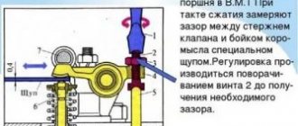
- Don't forget to measure the distance between the sensor and the timing disk. In the normal position, the gap ranges from 0.6 to 1.5 millimeters.
First way to check
In this case, you will need an ohmmeter, which you will use to replace the resistance on the winding. According to the manufacturer's standards, the indicator ranges from 550 to 750 Ohms.
It's okay if your numbers are slightly different from the norm. If the deviations are serious, you will definitely have to replace the sensor.
It should be noted in fairness that the crankshaft position sensor on VAZ 2110 models rarely breaks down. Among the main reasons for its failure to function normally is the accumulation of dirt, mechanical damage, as well as banal factory defects.
Second method
Here you will need a voltmeter, a transformer and an inductance meter. It is advisable to measure resistance under compact temperature conditions.
Once the ohmmeter readings are obtained, arm yourself with an inductance measuring device. Normally, the device should show from 200 to 4000 units (millihenry).
Replacing the phase sensor on a VAZ-2112 16 valves with your own hands
Replacing the phase sensor on a 16-valve VAZ-2112 engine is as easy as replacing the knock sensor. So, any car enthusiast can carry out this process without much effort.
The video describes the process of checking and selecting a new phase sensor for 16-valve cars of the VAZ 2110-2112 family:
The video material will tell you about the process of replacing the phase sensor, give some recommendations, and also talk about the nuances.
Checking the DPKV for serviceability
Also, the motorist should not forget to measure the clearance between the synchro disk and the sensor before dismantling, which cannot go beyond the size of 0.6-1.5 mm. If there are no mechanical damage such as scratches, dents, or damage to the material structure, the sensor is checked using other measuring instruments:
checking with an ohmmeter. In this case, it is necessary to measure the resistance of the sensor winding
Since the standard value of this indicator, set by the manufacturer, ranges from 550 to 750 Ohms, going beyond the specified limits indicates the malfunction of this device, which is important for the correct operation of the car - which means it is faulty. It is worth noting here that the manufacturer still allows a slight discrepancy in resistance with the nameplate values, but in any case they must correspond to the data specified in the machine’s operating instructions; checking with a voltmeter, inductance meter and transformer
This method is more complicated, but more effective - the resistance is measured with the same ohmmeter, after which the inductance is checked (should be from 200 to 4000 millihenry), with a sensor winding voltage of 500 Volts. Next, you need to measure the resistance with a megger and make sure that it does not exceed 20 MOhm.
If the sensor still does not pass these tests, it must be replaced. During this procedure, it is necessary not to forget about the distance between it and the synchronization disk regulated by the manufacturer, as well as alignment with the marks on the crankcase that were made on the previous device. Before installing a new sensor, be sure to check it, since even if all installation procedures are followed correctly, it may not work properly.
A new DPKV is checked according to the same procedure as a supposedly faulty one, and based on the test results, the device can be installed instead of the previous one or rejected. When installing, the bolts are tightened with a torque of 8 to 12 Nm. However, in any case, before carrying out all the actions to replace a rather expensive and hard-to-reach component, you should definitely make sure that it is the one that has failed, because cars produced by our automotive industry can often bring unpleasant surprises.
First way to check
In this case, you will need an ohmmeter with which you will replace the resistance on the winding. According to the manufacturer's standards, the indicator ranges from 550 to 750 Ohms.
It's okay if your numbers are slightly different from the norm. If the deviations are serious, you will definitely have to replace the sensor.
It should be noted in fairness that the crankshaft position sensor on VAZ 2110 models rarely breaks down. Among the main reasons for its failure to function normally is the accumulation of dirt, mechanical damage, as well as banal factory defects.
Features of testing on other cars
As for other cars, for example, VAZ-2109 with an injection engine, VAZ-2112 and VAZ-2114, their check is carried out identically to the VAZ-2110 car.
It is noteworthy that for VAZs, when checking the resistance of the crankshaft sensor coil, an additional check can be carried out.
But to do this, the multimeter must be switched to voltmeter mode with a measurement limit of 200 mV.
Then connect the probes to the DPKV terminals and pass them with any metal object, for example, a screwdriver, at a short distance from the core.
If the sensor is working properly, it will react to metal, the multimeter will show voltage surges on the display. The absence of these bursts will indicate a faulty element.
As for a car like the Reno Logan, the difference from the VAZ in this car comes down to slightly different readings of the resistance of the sensor coil when measured with an ohmmeter.
A working Logan DPKV has a normal resistance of 200-270 Ohms.
For Daewoo Lanos, the coil resistance should be in the range of 500-600 Ohms.
But on the ZMZ-406 engine, installed on Volga and Gazelle cars, the normal coil resistance is in the range of 850-900 Ohms.
Second method
Here you will need a voltmeter, a transformer and an inductance meter. It is advisable to measure resistance under compact temperature conditions.
Once the ohmmeter readings are obtained, arm yourself with an inductance measuring device. Normally, the device should show from 200 to 4000 units (millihenry).
A megger measures the resistance when the crankshaft position sensor winding is powered at 500 volts. Under normal conditions, the readings will be no more than 20 MΩ.
Finding the problem
Before replacing this element, it is necessary to determine the presence of a problem and make sure that the vehicle malfunction is based specifically on a violation of the functionality of this device.
Article on the topic: Interior improvements on the VAZ 2110
Symptoms of a malfunctioning camshaft sensor may be as follows:
- The engine does not start, or the engine starts with difficulty;
- The speed fluctuates, there are jerks, the car is unstable at idle;
- At high speeds, jerking is observed while driving;
- The engine sometimes stalls at the most unpredictable moment.
Replacing the DPRV
Replacing the phase position sensor of a VAZ 2112 16 valves is not difficult. Fastening to the internal combustion engine is carried out with two bolts, which are unscrewed with a 10mm socket wrench. Let us consider the replacement process step by step.
- We de-energize the car by removing the ground from the battery.
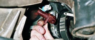
- Remove the terminal block from the sensor.
- Unscrew the fastening bolts with a socket wrench.
- Carefully pull the part and remove it.
- We install a new DPRV and carry out the work in the reverse order.
For proper operation of the position sensor after replacement, the mounting gap must be within 0.5–1.2 mm.
The camshaft sensor for a VAZ is inexpensive, but if you operate a car with a faulty device, this will lead to more complex and expensive breakdowns to repair.
Changing the oil seal
Below is a step-by-step manual for changing the camshaft oil seal for a VAZ 2110 car. The instructions are relevant for 16- and 8-valve engines. If you notice a new knocking noise coming from the camshaft, then, apparently, you need to disassemble it. Most likely, the knocking will go away after replacing the element. The part itself must be purchased in accordance with the manufacturer's specifications.
As for the characteristics themselves, the component must correspond to the dimensions of the part installed in a given car model. If the specifications are not met, you may have to go to the store for a new oil seal in the midst of repairs.
Articles
Instead of the numbers 2112-3706040, the article number 21120-3706040 is found. Both designations are correct. You can also find an article with the numbers -00, -01, -02... This is how the manufacturer is designated: 01 and 03 - “SOATE”, 00 - “Autoelectronics”, etc.
Parts with article number 2112-3706040-04
Recently, flexible lead sensors have been launched. The length of the wires is 15 cm. So far there is nothing like this in retail. But the article numbers remained the same - 2112-3706040-XX.
VAZ-2112 sensors 16 valves and their location: diagram, photo, video
Replacing the temperature sensor on a VAZ 2110 in 5 minutes! The efficient operation of the injection engine is ensured by a set of sensors. They all connect to the ECU. Lada hatchbacks of the 2112 family were produced only with injection engines, and two varieties of these internal combustion engines are 16-valve. We will talk about them further. All VAZ-2112 sensors, their location and appearance will be shown in the photo.
The excess oil pressure sensor, which is not connected to the ECU, is shown in the video.
Understanding the oxygen sensor
It is necessary to determine the sensor articles not by the engine model or even by Euro standards, but only by the ECU unit.
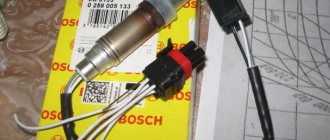
The number of oxygen sensors can be two or one - it all depends on environmental standards. AvtoVAZ also used two types of sensors - 0 258 005 133, 0 258 006 537 (BOSCH part numbers). The first of them are compatible with BOSCH M1.5.4, MP7.0 and January 5.1 controllers. Newer sensors were connected to the BOSCH M7.9.7 ECU (January 7.2). The two different types of sensors differ even in appearance.
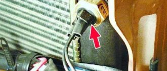
The ECU unit in “Dozens of VAZs” is located under a plastic cover. It is located near the front passenger's foot.
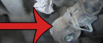
The red arrow marks the first, that is, the main sensor. The top photo corresponds to engine 21124 (1.6 l).
VAZ-21120 engines (1.5 l) could meet the Euro-3 standard, and then an “extended” catalyst was welded behind the main sensor. The second sensor was located behind it, that is, behind the “can”. Let's clarify:
- The Euro-2 standard corresponds to a design with one sensor (main);
- During the transition to Euro-3 standards, a second sensor was added (blue arrow).
By the way, the 24th engine can meet Euro-4 standards.
Which VAZ engines have a phase sensor
Main set of sensors for 16-valve VAZ-2112 engines
The ECU must control many parameters at once
The most important information will be the position of the crankshaft. You can turn off all sensors except the DPKV, and this will not lead to the engine stopping
Let's list all the elements one by one:
Let's take a look at how all the elements look in real life. Shown are pictures of VAZ-2112 sensors (16-valve internal combustion engine).
Everything said above is true for two engines at once - for units 21124 and 21120 (1.6 and 1.5 l).
You cannot unscrew the DTOZH sensor without draining the coolant. And to disconnect the sensor means to disconnect the connector, but not to dismantle the sensor itself.
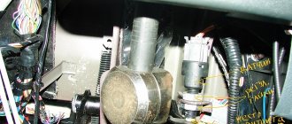
Where is which sensor located - engine compartment diagram
Let's look at another picture.
It is important to understand where the following elements are located:
The location of the phase sensor is indicated in the previous chapter.
How to check Niva Chevrolet phase sensor
Never unscrew the speed sensor. It will be difficult to install it in a way that maintains a seal.
Articles
For oxygen sensors, the designation 21120-3850010 was first used. Then an article appeared with the numbers 1118 (see photo). It appears to be a new type of sensor. It will be easier to use BOSCH articles.
We list the article numbers of the remaining sensors:
- Mass air flow sensor (21124 or 21120): 21083-1130010-01, -10, -20;
- Mass air flow sensor (motor 21120 with ECU January 4.1): 2112-1130010, -01;
- DPDZ: 2112-1148200;
- РХХ: 2112-1148300-02;
- DPKV: 2112-3847010, -01, -03, -04;
- DTOZH: 2112-3851010, -01, -02, -05;
- Speed sensor: 2110-3843010-13, -18;
- DPRV: 2112-3706040, -02, -03;
- DD: 2112-3855020, -01, -02, -03;
- Oil pressure sensor: 2106-3829010, -01, -02;
- Antifreeze level sensor: 2110-3839310-10, -11, -12, -13, -14;
- Coolant temperature indicator sensor: 2101-3808600, -02, 2106-3828010.
The last three sensors are not connected to the ECU. However, a rough road sensor (2123-1413130) can be connected. It affects the operation of the engine, although it is attached to the body.
Engines with ECU January 4.1 do not have oxygen sensors.
In general, on VAZ-2112 hatchbacks, sensors may be different from those indicated in the list. But then we are talking about an 8-valve engine. And everything that we indicated applies to 16 valves, here is a diagram of this engine.
Checking the coolant temperature sensor VAZ 2110
Camshaft sensor
Purpose
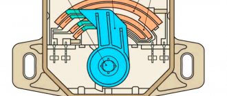
The components of the camshaft are elliptical cams, each of which acts on its own personal valve, that is, the task assigned to the camshaft is to control the exhaust and intake valves.
Although it is driven by a belt drive from the crankshaft, its speed is half the speed of the crankshaft. Appearance
Unfortunately, it is impossible to determine which phase of engine operation is currently in operation only by the position of the crankshaft (the compression stroke with the accompanying ignition of the fuel mixture or the moment of exhaust gas emission), then the camshaft position sensor helps the electronic control unit determine the desired phase gas distribution mechanism. The photo below shows how the camshaft acts on the valve: The camshaft cam (1), rotating, acts on the valve (4) through the pusher (2) and the spring (3), the valve seat (6) opens and through the channel (5) the exhaust gases/fuel mixture moves from/to the chambers/combustion chamber (7).
Operation of the gas distribution mechanism
Principle of operation
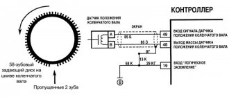
In the domestic automotive industry, sensors that help the engine control system determine the desired phase of the gas distribution mechanism began to be used in contactless ignition systems of carburetor “eights”. It was installed in a distributor, and its operation was also based on the so-called Hall effect. This sensor removes and transmits to the commutator the signal received from a metal shutter that has one slot, which is attached directly to the crankshaft gear (1).
The relative position of the metal disk and the phase sensor
That is, the curtain itself (2) is constantly located between the magnet and the sensor (3) that reads its signals, thereby preventing it from reading the magnetic lines. The slot (4) serves to generate and supply a pulse from the sensor to the electronic control unit (switch). The presented design is designed in such a way that the phase sensor informs the switch with a pulse precisely at the moment when the compression stroke occurs in the first cylinder. Pulse parameters: slot opposite - the voltage is almost zero, slot to the side - the voltage is almost equal to the voltage in the on-board circuit.
Sensor differences
The above-described design is called slotted and is used in the control system of a 16-valve engine on a VAZ 2112/2110. On a VAZ 2115, replacing the camshaft sensor is somewhat different, since VAZ engines of the 2111 and 21214 series are equipped with end-type phase sensors. It also works on the principle of the Hall effect, only its design does not use a slot, but a special setting mark. In this case, the pulse passes when the tag approaches the phase sensor. Since the distance between them is much smaller than between the sensor and the camshaft itself, when approaching, the magnetic field of the sensor changes, which contributes to the formation of a synchronizing pulse. On engines of the 2111 series, this mark is located on the camshaft itself, and on the 21214 series - on its drive pulley.
Symptoms of a problem
Most often, malfunctions in the camshaft timing sensor occur due to simple contamination of the contacting surfaces and a break in the power circuit, in which case:
- The “CHECK” indicator light is on;
- The engine starts only after prolonged rotation by the starter (about ten revolutions);
- Power drops slightly with a simultaneous increase in fuel consumption (problematic to determine);
- Deterioration in dynamics, dips appear during acceleration.
These failures won’t be able to cause anything catastrophic to the engine, but it’s still advisable not to delay repairs, since the cost is low.
Lada 2110 21114 1.6 8V 2007 MT › Logbook › Error P0340 2110 phase sensor DF, DRV
A check was displayed, after connecting the laptop the program showed an error - P0340 for the phase sensor or as it is also called the camshaft sensor. I decided that the sensor had died and replaced it with a Kaluga one purchased on the market. The error went away, I sighed. About a month later, the same situation, again an error in DF. I removed the terminal from it and saw that the positive contact i.e. the middle one has oxidized. I picked up contact cleaning aerosols from the market, treated it, and let it dry for 15 minutes. And since the contacts themselves were already approaching, I decided to press them a little with a screwdriver, somehow it was possible... but not of good quality due to the design of the contact itself. I put the sensor back and decided to observe. I started it, drove about 50 meters, the check light came on, I think everything is repeating itself again, after driving a little more, the car warmed up to operating temperature and the error disappeared, I think miracles! After traveling for a couple of days, the situation is the same. I think DF has given a long life again. I bought a new sensor, again from Kaluga, but in a different market. I installed it, the error went away, but I think I found the problem, as a version - in the oxidized contact, because of this, the sensor died, and the error went away after the engine warmed up, because along with the warming up, both the sensor and the contact warmed up. After riding for three weeks this time, this error came to me again
Finding the cause of error P0340
Using a diagnostic scanner, you need to make sure that there is an error. After this, you can begin to search for the culprit of its appearance:
- Check the DPRV wiring (between the connector and the sensor) for damage, short circuit or corrosion.
- Check the sensor connector for mechanical damage or corrosion.
- Check the wiring from the connector to the ECU for damage, short circuit or corrosion.
- Eliminate the causes of other errors that are stored in the ECU memory, which may be related to the operation of the DPRV.
- Use a scanner or oscilloscope to check the voltage of the DPRV for compliance with performance indicators (individually for each car).
- If the DPRV voltage readings are incorrect, the sensor must be replaced.
- If the voltage reading is within the normal range, the engine control module may be faulty. It may need to be replaced or reprogrammed.
Common mistakes when diagnosing P0340
Before replacing the DPRV, it is very important to carefully check the wiring and connectors of the sensor to eliminate these causes of malfunction. Very often this is not done, and replacing the sensor does not help solve the problem.
Another common mistake is that the diagnostician does not take into account the problem with the presence of misfires or a malfunction of the crankshaft position sensor (CPS). These factors can cause the P0340 code to appear.
Read all the details about checking the camshaft sensor in our article - https://autofakty.com/datchik-polozheniya-raspredvala-raspolozhenie-neispravnosti-proverka/