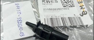
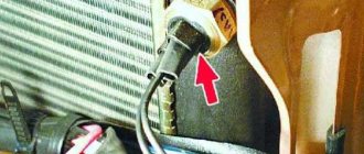
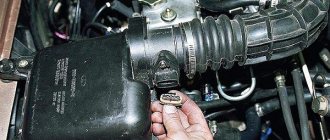
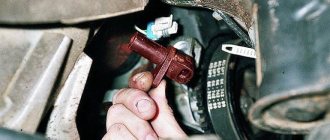
When signs of a faulty camshaft sensor appear, most often the engine begins to operate in pair-parallel mode when fuel is supplied. This leads to the fact that each of the nozzles begins to work 2 times more. As a result, more fuel is spent on vehicle operation, and a double portion of toxic exhaust is released into the environment. Self-diagnosis may be difficult. If the sensor has become unusable, do not delay replacing the element.
Main function of the sensor
Before moving on to the symptoms of a faulty camshaft sensor, it is useful to consider what the device is. The main option of the sensors is to determine the localization of the mechanism that distributes gases in a certain period of time. This is required so that the electronic control unit promptly sends a command to supply fuel. In addition, the sensor determines the location of the cylinder. Another equally important function is ignition synchronization. The sensor works in conjunction with the crankshaft position sensor.
Phase sensors are used on engines with distributed phased injection. They are also used on engines that use a variable valve timing system. In this case, separate sensors are often used for the camshafts that control the intake and exhaust valves.
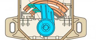
Modern devices operate by using a physical phenomenon called the Hall effect: current flows in a semiconductor wafer. When it moves in a magnetic field, a difference between potentials occurs. The sensor contains a magnet, which looks like a rectangular plate. It uses semiconductor material. The contacts are connected to all 4 sides, the first pair works as an input, the second pair as an output. Voltage is applied to the first ones, and the signal is eliminated to the second ones. The entire process is carried out on the basis of received commands that arrive from the electronic control unit in a certain period of time.
It is customary to distinguish two types of sensors:
Slotted.
Tortsevoy.
The difference is only in the form, and the work occurs according to the same algorithm. There is a benchmark or mark on the surface of the camshaft. As it begins to rotate, a magnet built into the sensor body begins to record how it passes. There is also a system in the housing that converts the signal into information that the control unit can recognize.
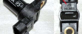
The second type of sensor has a constantly working magnet at the end, which establishes the passage of a reference point near the element. The first type uses the “P” shape. The reference point on the distribution disk passes between two “slots”.
In injection gasoline engines, the master disk and the phase sensor are adjusted in such a way that a pulse from the sensor is generated and transmitted to the ECU at the moment the first cylinder passes its top dead center. This ensures synchronization of fuel supply and the moment of spark supply to ignite the air-fuel mixture. Obviously, the phase sensor has a direct impact on the operation of the engine as a whole.
Signs of a faulty phase sensor
If you have the following symptoms, then the phase sensor (dph) is most likely faulty.
- When starting the engine, the starter spins for 3-4 seconds, then the engine starts and the check engine lights up. In this case, during startup, the computer waits for readings from the phase sensor, does not wait and switches to engine operating mode relying on the ignition system (according to DPKV).
- Increased gasoline consumption. (Also read: Reasons for high fuel consumption on VAZ).
- Self-diagnosis mode failures.
- Reduced engine dynamics. (the reason may also be the mass air flow sensor and low engine compression).
The main “symptoms” of a malfunction
If the sensor fails partially or completely, the electronic control unit begins to forcibly transfer the engine to the stage of paraphase fuel injection. That is, fuel injection is carried out in accordance with information taken from the crankshaft. Therefore, each injector begins to inject fuel 2 times more often. This is necessary to ensure that the air-fuel mixture will be formed in each cylinder. But this does not happen at the right time, so the engine power begins to gradually decrease, and as a result, more fuel is wasted.
A faulty camshaft sensor has the following symptoms:
increased fuel consumption;
the level of toxicity of exhaust gases increases, so an unpleasant specific smell will be felt. Especially if the catalyst is knocked out;
engine operation ceases to be stable, most often this can be seen at idle speed;
the acceleration dynamics of the car begins to decrease, as does the engine power;
The “Check Engine” sign lights up on the dashboard. While performing a scan, error p0340 occurs;
when the engine starts, the starter starts idling the engine for 3-4 seconds, and then the engine starts to start. This is due to the fact that in the first seconds the electronic unit does not receive the necessary information from the sensor, and then goes into emergency mode automatically based on the data transmitted by the crankshaft.
A malfunction of the phase sensor can lead to difficulties in the process of self-diagnosis of the vehicle. When starting the engine, the driver must turn the starter longer, most often 6-10 seconds are enough. Depends on the make and model of the car. At this moment, activities related to self-diagnosis of the electronic control unit take place. Therefore, errors occur and the engine begins to operate in emergency mode.
Operating principle of the camshaft sensor
Functionally, the camshaft sensor is tightly connected to the crankshaft rotation sensor. The camshaft sensor has a permanent magnet that creates a magnetic field. The voltage change occurs in the semiconductor.
When the reference point closes the magnetic gap, the magnetic field changes. A reference point (this is a metal tooth or pin), which is located on the master disk attached to the camshaft or on the camshaft gear.
The engine control unit, receiving signals from the camshaft sensor, reads the position of the piston of the 1st cylinder at TDC, then the control system provides sequential fuel injection and ignition of the mixture in accordance with the operating order of the engine cylinders.
The operating principle of the sensor automatically gives answers to questions about where the camshaft sensor is located and what the camshaft sensor is responsible for.
What happens if the camshaft sensor fails? The warning lamp turns on and the control unit switches the timing belt from the phased injection mode to the reserve mode. This means that fuel is supplied to all cylinders at the same time. Accordingly, fuel consumption increases. The only solution is to replace the faulty camshaft sensor.
Expert opinion Ruslan Konstantinov Expert on automotive topics. Graduated from Izhevsk State Technical University named after M.T. Kalashnikov, specializing in “Operation of transport and technological machines and complexes.” More than 10 years of professional car repair experience.
Problems with the camshaft position sensor cannot be determined visually, and special equipment will be required to check the device. However, a sensor malfunction is easily determined by computer diagnostics; if you have a special adapter and an application on your smartphone, you can carry out diagnostics and identify the malfunction yourself.
Typically, problems with the DPRV arise either due to a malfunction of the sensor (short circuit, wear and breakage of the disk teeth), or due to high temperature (with systematic overheating of the engine), as well as if the sensor has moved due to broken fasteners. Sensor malfunctions are characterized by symptoms that could theoretically indicate other problems with the internal combustion engine:
- increased fuel consumption;
- the ECM is operating in emergency mode;
- The "Check Engine" light is on on the dashboard.
In addition, many motorists are faced with a loss of power (the car simply cannot accelerate), the engine may stall, popping sounds appear in the exhaust pipe, etc. Some cars with an automatic transmission may experience problems with the transmission (locking in one of the gears), The problem goes away for a short time if you turn off and start the engine again. On some cars, malfunctions of the camshaft position sensor can negatively affect sparking, as a result of which the engine cannot be started at all.
The occurrence of breakdown of sensors on cars with LPG
It was noted that the manifestation of signs of a malfunction of the camshaft sensor with a diesel or gasoline engine is not so acutely noticed. As a result, drivers continue to operate the car for some time after the sensor has stopped working normally. But in the case when the car is equipped with gas equipment above the fourth generation (where smart devices operate), the engine begins to work intermittently, and discomfort appears while driving.
This includes a significant increase in fuel consumption and a significant reduction in engine power and dynamics. All this happens due to a mismatch in the operation of the program of the electronic engine control unit and the LPG control unit. Based on this, when using gas-cylinder equipment, it is recommended to change the phase sensor immediately after identifying a malfunction. Using a machine with a damaged camshaft position sensor harms not only the engine, but also the gas equipment itself and its control system.
Phase sensor error
If the sensor malfunctions, the check light comes on and error P0340 pops up - “Phase sensor error” or “camshaft position sensor is faulty.” But as was already said from the very beginning, the description of the problem is different, but the essence is the same: (I repeat once again) the phase sensor and the camshaft position sensor are the same sensor. For more information about the occurrence of the error and how to resolve it, read the article: Phase sensor error Most often, repairs are simple: you need to replace the sensor with a new one (How to replace a phase sensor?).
Why do breakdowns occur?
The causes of the camshaft sensor malfunction primarily lie in the appearance of wear, which is a natural process. Even the highest quality parts gradually deteriorate and require replacement. Most often due to the influence of high temperature when the engine is running, the effects of vibrations present in the housing sensor. As a result, contact damage occurs. The magnet gradually demagnetizes, and mechanical damage to the housing appears.
Another reason is problems with the wiring in the sensor. For example, the signal wires or power supply are broken, so the sensor stops supplying voltage or the signal does not pass through the wire. Sometimes there is a mechanical breakdown on the “ear”. Even less often, the fuse that is responsible for the operation of the phase sensor breaks.
How to choose a phase sensor
The phase sensor, otherwise called the camshaft position sensor (abbr. DF and DPRV, respectively) or CMP, is one of the most important elements of the engine management system that uses diesel or gasoline fuel. It is this sensor that is responsible for taking into account the position of the timing electronics and allows other control elements to monitor the operation of the entire system. Functionally, the sensor is connected to the DPKV (crankshaft position sensor), the features of which were described in this material. Working in tandem, these sensors send data to the control unit, which gives impulses to both fuel injection and ignition operation in each of the engine cylinders. About the design of the phase sensor, its malfunctions and selection features - in the material Avto.pro.
Basic check options
To check the operation of the internal combustion engine phase sensor, special equipment is used, including an electronic multimeter. The device can operate in constant voltage mode. As an example, we can take the phase sensors of the VAZ 2114 vehicle. On 16-valve modifications, a 21120 sensor is installed, and on an 8-valve version, 21110.
Before you begin to carry out diagnostic measures, you need to dismantle the sensors from their location. Next, a visual inspection of the phase sensor housing, contacts and block is carried out. If accumulations of dirt and dust are found, you need to use gasoline or alcohol to remove the dirt.
To check the sensor on an 8-valve modification, it is connected to a battery and a multimeter.
In the future, the algorithm of actions will be as follows:
The supply voltage is set in the range of 13.5 Volts (acceptable error is ±0.5). To organize power, it is enough to use an ordinary car battery;
The voltage between the power wire and ground should not be less than 90% of the supply voltage. Otherwise, if the value tends to zero, it means the sensor is faulty;
a steel plate is brought to the end of the sensor;
when the sensor is operating normally, the voltage between ground and signal wire should not exceed 0.4V. If the value is higher, the device is not working;
move the steel plate away from the end of the sensor. Then the voltage should return to the original data from 90% of the supply voltage.
To check the 16-valve modification sensor, it is connected to a power supply and a multimeter.
To check, you need to prepare a metal part with a size of up to 20 mm, a length of 80 mm and a thickness of 0.5 mm. The testing principle is similar to that presented above for the 8-valve model, but the values will be different:
The supply voltage is set in the range of 13.5 Volts (±0.5 error allowed);
when the sensor is operating normally, the voltage between ground and signal wire should not exceed 0.4V;
a pre-prepared steel part is placed in the slot, where the camshaft reference is;
if the device is working, the voltage between the power wire and ground should not be less than 90% of the supply;
remove the plate to the side, then the voltage should again drop to 0.4V.
These types of checks can be performed even without removing the sensor from its workplace. However, to examine it better, you need to remove it. Often, when checking a sensor, it makes sense to check the functionality, the absence of mechanical damage to the wires, and the quality of the contacts. For example, there are often cases when the chip does not hold contact well, which is why the sensor does not send a signal to the control unit. Also, if possible, it is advisable to “ring” the wires going from the sensor to the ECU and to the relay (power wire).
In addition to checking with a multimeter, you need to check for relevant sensor errors using a diagnostic tool. If this kind of error is detected for the first time ever, then you should try to reset it using software. Or simply disconnecting the negative terminal of the battery for a minute can help. If the error still remains, additional diagnostics are needed using the above algorithms.
How to find and install a new sensor
Finding the camshaft position sensor is not that difficult. Let us immediately note that these sensors are usually not interchangeable, so you cannot make a mistake when searching. On the positive side: you can easily install the new device yourself
, so you don’t have to turn to service station workers for help. But to find the sensor itself, you can follow:
- Vehicle VIN code;
- Article number of the existing sensor;
- Complete data about the car.
Avto.pro has an excellent system for searching for spare parts based on vehicle data. There is also a full text search that allows you to search for parts using specific wordings. For example, "Mazda 3 bumper". In the case of a phase sensor, we still recommend conducting a manual search in the electronic catalog. This is quite simple, since the car enthusiast will move through the tree-like catalog, first selecting the make, then the car model, and only then the spare part category
. It is important to indicate for which engine the phase sensor is selected. At the end of the search, the car enthusiast will also receive a list of sensor articles that are compatible with the system of his vehicle - if necessary, they can be used to conduct a search in other stores.
When searching for automotive electronics, you should be guided not only by its compatibility with your vehicle, but also by who produces the electronics. There are two win-win options: buying an original or buying a spare part from a supplier for the conveyors of automakers
(the same original, but under the name of the manufacturer’s own brand). It is worth paying attention to phase sensors from such companies:
Installing a new phase sensor is easy. It is necessary to remove the “-” from the battery, get to the sensor, remove its chip and unscrew its fasteners using a socket wrench. After removing the old sensor, install the new device in its seat. We also recommend replacing the rubber seal of the sensor with a new one (if it is included with the new device) and measuring the mounting gap between the sensor and the marker. The gap width should be in the range of 0.5 – 1.2 mm
. After this, you need to tighten the fastening element and connect the chip - the new sensor is ready for use.
Checking the functionality of a sensor with two wires
To correctly complete the procedure, it is recommended to follow the following procedure:
If a vehicle has a camshaft sensor with two wires, it means that the automaker has installed a magnetic type of CMP sensor on the vehicle. Therefore, the multimeter is set to a different mode with variable voltage;
It is better to take a second person with you so that he can turn the key without activating the engine;
Next you need to check for the presence of electricity. It must pass through the sensor circuit. To do this, you need to take the contact of the multimeter and lean it against any metal component on the engine. The second contact of the equipment will need to be placed against each wire attached to the camshaft sensor connector. If there is no electrical current on any of the wires, then the camshaft sensor is completely faulty;
Ask a second person to start the engine again;
Place the contacts of the measuring device against one wire of the camshaft sensor, and connect the other contact to the second wire of the sensor. View the value on the multimeter display. Check the indicator with the technical information specified in the vehicle repair manual. In most cases, you will see a fluctuating signal from 0.3 – 1V;
If the signal does not appear on the display, then the camshaft sensor is not working.
How to check the camshaft position sensor
Testing an inductive DPVR and a sensor based on the Hall effect are similar. In the process, the voltage value between their terminals is measured. To do this, you will need a multimeter that can measure DC voltage. Checking the operation of the sensor should begin with the following procedures:
DPRV with three terminals
- Check the connection of the sensor to the signal wiring harness. It should be connected to +12 V and ground (see figure).
- If there is power and ground to the sensor, then you need to start the engine and check for the presence of pulses on the signal wire.
- Check for moisture in the connector. To do this, you need to disconnect the plug with signal wires from the sensor and check the dryness of the plug and socket itself. If there is oxidation or contamination, clean and dry.
- Check the insulation of the signal wires. Statistically, its damage is the most common cause of malfunction. The fact is that the sensor is located in close proximity to the engine. Therefore, the insulation heats up and over time breaks and crumbles, leading to a short circuit.
- Check the inductive sensor's insulation resistance value. As a rule, it is about 0.5...1 kOhm. For some sensors it will be several kOhms (check the manual for your car for detailed information). The main thing is that the insulation is not broken.
Scheme for checking DPRV
You can check the operation of a sensor based on the Hall effect in the following way. To do this, assemble the circuit shown in the figure. In the diagram: 1 - sensor body, 2 - plug block, 3 - resistor with a resistance value of 0.5...0.6 kOhm, 4 - AL307 LED, 5 - metal object (for example, a screwdriver). A car battery is used as a power source. To check, you need to move a metal object near the sensor. If it is working properly, the LED should light up briefly. If this does not happen, it means the sensor is faulty.
There is another way to test a sensor based on the Hall effect. We disconnect the sensor from the connector, and connect a multimeter to its terminals in DC voltage measurement mode. Turn on the ignition. The voltage value between the “ground” of the sensor and the general “ground” should be 0 V. And the voltage between the common “ground” and the power contact of the sensor should be within 10...12 V. A metal object must be moved near the body. If the values on the multimeter change, the sensor is working. Otherwise, no.
Checking a two-wire (inductive) sensor
If your machine has a two-wire DPRV (inductive type), then it must be checked in the following sequence:
- Set your multimeter to AC voltage function.
- Turn the ignition key without starting the engine.
- Check for voltage in the circuit. To do this, connect one contact of the multimeter to ground, and with the other, check each wire in the DPRV connector. If there is no voltage on any of them, the sensor is completely faulty.
Another way is this:
- Start the car engine.
- Connect one contact of the multimeter to one wire of the sensor, the second contact to the other. If the sensor is working properly, then you will see a fluctuating voltage on the tester in the range of 0...5 V (check the exact value in the manual of your car). If there is no voltage, the sensor is faulty.
Checking three-wire DPRV
Testing a sensor based on the Hall effect is carried out according to the following algorithm:
- Set the multimeter to DC voltage measurement mode.
- Turn the key in the ignition, but without starting the engine.
- Connect one contact of the device to ground. The other contact is to the sensor power wire. Compare the voltage obtained with that indicated in the manual for your car.
Another way:
- Start the engine.
- Connect one contact of the multimeter to the black wire of the sensor, the second contact to the red (power wires). The resulting voltage value must match that specified in the machine manual. If there is no electricity at the contacts, the sensor has failed.
Typically, the camshaft position sensor cannot be repaired. Therefore, if it fails, you need to buy a new one. Its price is about $4...10 depending on the brand of sensor and car.
Replacement
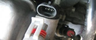
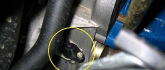
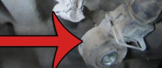
The location of the camshaft sensor is located near the air filter near the cylinder head. On VAZ cars it is located near the first cylinder.
To remove the sensor, you need to disconnect the fixing chip and unscrew the bolt with a 10mm wrench. Also, during removal, the sealing ring may be damaged, in which case it must be replaced and the new ring must be treated with automotive oil. Only after this is the sensor installed back.
Repairing the camshaft sensor of the VAZ family does not make much sense, since its cost is within 350 rubles and it will be easier to purchase a new one and replace it. But you can try to revive the old DPRV by cleaning the contacts on the fixing chip. If the problem is not solved, then it is better to buy a new one. Also, some drivers change their camshaft sensors every few months, which is definitely too frequent a change. In this case, it is recommended to check the electrical system in the car.
WHAT DOES THE CAMSHAFT POSITION SENSOR DO?
The Mazda 6 camshaft position sensor is an important part of the engine management electronics. As the camshaft rotates, the sensor readings inform the engine control computer about engine speed and rpm. The computer then uses this signal to help set the timing, synchronize the fuel injectors, and control the pulses sent to the engine's ignition system.
The camshaft position sensor is located on the cylinder head, the cylindrical part is inserted into the cylinder head, receives a signal about the camshaft speed, and sends the data to the engine ECU. These parts usually fail due to corrosion of electrical connectors or exposure to high temperatures.
