If the brakes are faulty, driving a car is strictly prohibited, so it is important to monitor the condition of the brake system. The brake system needs to be monitored and repaired in a timely manner, and repairing the brake system on a VAZ 2110 is not lengthy and labor-intensive, but if you lack the skills and tools, it is better to contact specialists.
In order to know for sure whether the technical condition of the most important function of the car is in order, you need to understand how the brake system on the VAZ 2110 is designed. What sore spots do all the well-known “ten” have and how to solve possible or already pressing problems yourself.
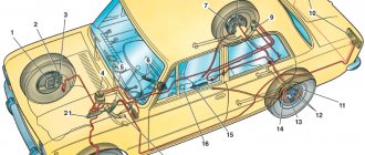
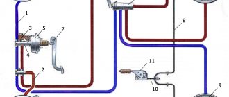
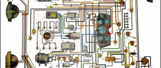
Hydraulic brake circuit diagram
1 – front wheel brake mechanism; 2 – pipeline of the “left front–right rear brake” circuit; 3 – main cylinder for hydraulic brakes; 4 – pipeline of the “right front–left rear brake” circuit; 5 – master cylinder reservoir; 6 – vacuum booster; 7 – rear wheel brake mechanism; 8 – elastic lever of the pressure regulator drive; 9 – pressure regulator; 10 – pressure regulator drive lever; 11 – brake pedal; A – flexible hose of the front brake; B – flexible rear brake hose
The car uses a working brake system with diagonally separated circuits, which ensures high active safety of the car. One hydraulic drive circuit ensures the operation of the right front and left rear brake mechanisms, the other - the left front and right rear.
If one of the circuits of the service brake system fails, the second circuit is used to stop the vehicle with sufficient efficiency.
The hydraulic drive includes a vacuum booster 6 and a dual-circuit pressure regulator 9 for the rear brakes.
The parking brake system is driven by the brake mechanisms of the rear wheels.
Main causes of failure
The low number of elements in the handbrake system leaves us with few options for identifying the culprits.
In the vast majority of cases, the cable breaks. This is due to its use being too long or intensive.
Some drivers simply don’t understand that the handbrake is insurance, nothing more. The car should always be braked with the main brakes, which are designed for such a load. Of course, if they didn’t refuse you.
In addition, the cable can simply become jammed in its sheath, which can only be cured by replacement. For loose tips, the same procedure is carried out, and without fail. What will we do next?
Vacuum booster
1 – vacuum booster housing;
2 – amplifier housing cup; 3 – rod; 4 – adjusting bolt; 5 – rod seal; 6 – sealing ring of the master cylinder flange; 7 – diaphragm return spring; 8 – amplifier pin; 9 – tip mounting flange; 10 – valve; 11 – hose tip; 12 – diaphragm; 13 – amplifier housing cover; 14 – sealing cover; 15 – piston; 16 – protective cover of the valve body; 17 – air filter; 18 – pusher; 19 – pusher return spring; 20 – valve spring; 21 – valve; 22 – valve body bushing; 23 – rod buffer; 24 – valve body; A – vacuum chamber; B – atmospheric chamber; C, D – channels The rubber diaphragm 12 together with the valve body 24 divides the cavity of the vacuum amplifier into two chambers: vacuum A and atmospheric B. Chamber A is connected to the engine inlet pipe through the check valve of the tip 11 and a hose.
The 24 valve body is plastic. At the exit from the cover, it is sealed with a corrugated protective cover 16. The valve body contains the main cylinder drive rod 3 with a support sleeve, rod buffer 23, valve body piston 15, valve assembly 21, pusher and valve return springs 19 and 20, air filter 17 , pusher 18.
When you press the pedal, the pusher 18, the piston 15, and after them the valve 21 move until it stops against the seat of the valve body. In this case, cameras A and B are separated. As the piston moves further, its seat moves away from the valve and through the resulting gap, chamber B is connected to the atmosphere. The air entering through filter 17, the gap between the piston and the valve and channel D creates pressure on the diaphragm 12. Due to the difference in pressure in chambers A and B, the valve body moves along with the rod 3, which acts on the piston of the main cylinder.
When the pedal is released, valve 21 moves away from the body seat and through the resulting gap and channel C of chambers A and B communicate with each other.
Pressure regulator drive
1 – pressure regulator; 2, 16 – pressure regulator mounting bolts; 3 – bracket for the pressure regulator drive lever; 4 – pin; 5 – pressure regulator drive lever; 6 – axis of the pressure regulator drive lever; 7 – lever spring; 8 – body bracket; 9 – pressure regulator mounting bracket; 10 – elastic lever of the pressure regulator drive; 11 – earring; 12 – earring bracket; 13 – washer; 14 – retaining ring; 15 – bracket pin; A, B, C – holes
Pressure regulator
1 – pressure regulator housing; 2 – piston; 3 – protective cap; 4, 8 – retaining rings; 5 – piston sleeve; 6 – piston spring; 7 – body bushing; 9, 22 – support washers; 10 – sealing rings of the pusher; 11 – support plate; 12 – pusher bushing spring; 13 – valve seat sealing ring; 14 – valve seat; 15 – sealing gasket; 16 – plug; 17 – valve spring; 18 – valve; 19 – pusher bushing; 20 – pusher; 21 – piston head seal; 23 – piston rod seal; 24 – plug; A, D – chambers connected to the main cylinder; B, C – chambers connected to the wheel cylinders of the rear brakes; K, M, N – gaps
The pressure regulator regulates the pressure in the hydraulic drive of the rear wheel brakes depending on the load on the rear axle of the vehicle. It is included in both circuits of the brake system and through it brake fluid flows to both rear brake mechanisms.
Pressure regulator 1 (Fig. Pressure regulator drive) is attached to bracket 9 with two bolts 2 and 16. At the same time, front bolt 2 simultaneously secures fork bracket 3 of lever 5 of the pressure regulator drive. A double-arm lever 5 is hinged on the pin of this bracket with a pin 4. Its upper arm is connected to an elastic lever 10, the other end of which is pivotally connected to the rear suspension arm bracket through an earring 11.
Bracket 3 together with lever 5 can be moved relative to the pressure regulator due to the oval holes for the fastening bolt. This regulates the force with which lever 5 acts on the regulator piston (see subsection 6.4.2). The regulator has four chambers: A and D (Fig. Pressure regulator) are connected to the main cylinder, B to the left, and C to the right wheel cylinders of the rear brakes.
In the initial position of the brake pedal, piston 2 (see Fig. Pressure regulator) is pressed by lever 5 (see Fig. Pressure regulator drive) through leaf spring 7 to pusher 20 (see Fig. Pressure regulator), which is pressed against the saddle under this force 14 of valve 18. In this case, valve 18 is pressed away from the seat and a gap H is formed, as well as a gap K between the piston head and seal 21. Through these gaps, chambers A and D communicate with chambers B and C.
When you press the brake pedal, fluid flows through gaps K and H and chambers B and C into the wheel cylinders of the brake mechanisms. As the fluid pressure increases, the force on the piston increases, tending to push it out of the housing. When the force from the liquid pressure exceeds the force from the elastic lever, the piston begins to move out of the body, and after it, under the action of springs 12 and 17, the pusher 20 moves together with the sleeve 19 and rings 10. In this case, the gap M increases, and the gaps H and K decrease . When the gap H is completely selected and the valve 18 isolates chamber D from chamber C, the pusher 20, together with the parts located on it, stops moving after the piston. Now the pressure in chamber C will vary depending on the pressure in chamber B. With a further increase in the force on the brake pedal, the pressure in chambers D, B and A increases, piston 2 continues to move out of the body, and sleeve 19 together with o-rings 10 and plate 11 under increasing pressure in chamber B, it shifts towards plug 16. At the same time, the gap M begins to decrease. Due to the decrease in the volume of chamber C, the pressure in it, and therefore in the brake drive, increases and will be practically equal to the pressure in chamber B. When the gap K becomes zero, the pressure in chamber B, and therefore in chamber C, will increase less degree than the pressure in chamber A due to throttling of the liquid between the piston head and seal 21. The relationship between the pressure in chambers B and A is determined by the ratio of the difference in the areas of the head and piston rod to the area of the head.
As the vehicle load increases, the elastic lever 10 (see Fig. Pressure regulator drive) is loaded more and the force from lever 5 on the piston increases, that is, the moment of contact between the piston head and seal 21 (see Fig. Pressure regulator) is achieved at greater pressure in the main brake cylinder. Thus, the effectiveness of the rear brakes increases with increasing load.
If the brake circuit “left front – right rear brake” fails, the o-rings 10, bushing 19, under the fluid pressure in chamber B, will move towards the plug 16 until the plate 11 rests on the seat 14. The pressure in the rear brake will be regulated by part of the regulator, which includes piston 2 with seal 21 and bushing 7. The operation of this part of the regulator, in the event of a failure of the said circuit, is similar to the operation with a working system. The nature of the change in pressure at the outlet of the regulator is the same as with a working system.
If the brake circuit “right front – left rear brake” fails, the pressure of the brake fluid forces the pusher 20 with the bushing 19 and sealing rings 10 toward the piston, pushing it out of the housing. The M gap increases and the H gap decreases. When valve 18 touches seat 14, the increase in pressure in chamber C stops, that is, the regulator in this case works as a pressure limiter. However, the achieved pressure is sufficient for reliable operation of the rear brake.
There is a hole in housing 1, closed by plug 24. Liquid leakage from under the plug when it is squeezed out indicates a leak in rings 10.
Tips before starting work
Before bleeding the brakes on a VAZ-2110 with your own hands, prepare new hydraulic fluid. It must be the same brand that is currently used in the car. If you don't know what kind of fluid was used before, look at the instruction manual. There are several classes depending on the boiling point - from 3 to 5.1 (labeled “Dot”).
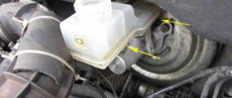
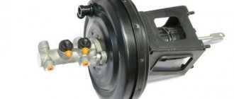
Master cylinder with reservoir
1 – main cylinder body; 2 – low pressure sealing ring; 3 – drive piston of the “left front–right rear brake” circuit; 4 – spacer ring; 5 – high pressure sealing ring; 6 – pressure spring of the sealing ring; 7 – spring plate; 8 – piston return spring; 9 – washer; 10 – locking screw; 11 – drive piston of the “right front–left rear brake” circuit; 12 – connecting sleeve; 13 – tank; 14 – brake fluid emergency level sensor; A – gap
Master cylinder with sequential pistons. A tank 13 is mounted on the master cylinder body, in the filler neck of which a sensor 14 for emergency brake fluid level is installed. The high pressure O-rings 5 and the rear wheel cylinder rings are interchangeable.
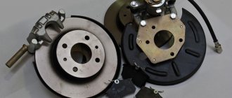
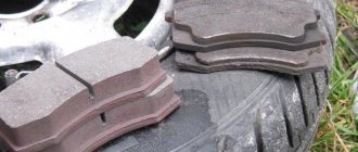
Front wheel brake
1 – brake disc; 2 – pad guide; 3 – caliper; 4 – brake pads; 5 – cylinder; 6 – piston; 7 – pad wear indicator; 8 – sealing ring; 9 – protective cover of the guide pin; 10 – guide pin; 11 – protective casing
The front wheel brake mechanism is disc, with automatic adjustment of the gap between the pads and the disc, with a floating caliper and a brake pad wear indicator. The bracket is formed by a caliper 3 and a wheel cylinder 5, which are tightened with bolts. The movable bracket is bolted to pins 10, which are installed in the holes of the guide 2 of the pads. Lubricant is placed in these holes, rubber covers 9 are installed between the pins and the pad guide. Brake pads 4 are pressed against the grooves of the guide by springs, the inner one of which has a lining wear indicator 7.
A piston 6 with a sealing ring 8 is installed in the cavity of the cylinder 5. Due to the elasticity of this ring, the optimal gap between the pads and the disk is maintained.
The design of the brake system of a VAZ car
On the front suspension there are:
- vacuum type amplifier;
- critical level indicator;
- disc brakes, which are equipped with ventilation;
- caliper assemblies having pistons;
- pad wear monitoring system;
On the rear suspension there are:
- brake drum;
- pads, the action of which is controlled by hydraulic pistons;
- master brake cylinder.
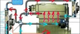
The brake cylinder is designed for automatic control. It is necessary to control the distance separating the block and the brake drum. The main brake cylinder is secured with two studs to a vacuum type booster. The expansion tank is mounted in the upper part of the GTZ. A sensor equipped with an electronic device is installed in the lid; it is necessary to monitor the liquid level. This allows you to determine when it will need to be replaced.
Installation of the plug in the upper part of the device cover. It is equipped with a spring necessary to return the structure to its standard position. The design of the GCC is double-circuit. Therefore, it contains pistons (there are two of them). They are in a longitudinal position.
The piston has a ring for sealing. In the braking device it is in contact with the rod. VUT 2110 is located between the unit responsible for the pedal and the main control center. It is secured with two studs. The design of the amplifier is non-separable; if it fails, it is recommended to replace it with a new one.
Wheel cylinder
1 – block stop; 2 – protective cap; 3 – cylinder body; 4 – piston; 5 – seal; 6 – support plate; 7 – spring; 8 – crackers; 9 – thrust ring; 10 – thrust screw; 11 – fitting; A – slot on the thrust ring
The rear wheel brake mechanism (Fig. Rear wheel brake mechanism) is drum-type, with automatic adjustment of the gap between the shoes and the drum. The automatic clearance adjustment device is located in the wheel cylinder. Its main element is a split thrust ring 9 (Fig. Wheel cylinder), installed on the piston 4 between the shoulder of the thrust screw 10 and two nuts 8 with a gap of 1.25–1.65 mm.
The thrust rings 9 are inserted into the cylinder with tension, providing a shear force of the ring along the cylinder mirror of at least 343 N (35 kgf), which exceeds the force on the piston from tension springs 3 and 7 (see Fig. Brake mechanism of the rear wheel) of the brake pads.
When, due to wear of the linings, the gap of 1.25–1.65 mm is completely removed, the shoulder on the thrust screw 10 (see Fig. Wheel cylinder) is pressed against the shoulder of the ring 9, as a result of which the thrust ring moves after the piston by the amount of wear. When the braking stops, the pistons are moved by the force of the tension springs until the cracks stop against the shoulder of the thrust ring. This automatically maintains the optimal clearance between the pads and the drum.
Installation
Installation is always carried out in the reverse order of dismantling. But in order not to get confused in this work, we will discuss this issue in more detail.
- To begin with, we need to push the piston of the brake system cylinder all the way inside.
- It is necessary to attach the handbrake rod to the new rear block. This must be done in exactly the same way as was the case with the old node, and in no other way.
- We put the cotter pin in place.
- How much we suffered before we pulled out the guide spring. Now it's time to bring her back. We attach it to the block.
- The cable is connected to the handbrake rod.
- The previously removed upper spring is now attached to the pads at one end and the other.
- Now get ready to perform the most important stage of the work: we place the block on the brake cylinder, in the place where it should be. We tighten it a little from below so that the spring stretches and makes it possible to place a spacer bar in the niche. We insert the bar. After this, we put the second block in place, but only so that it does not fit into the hole of the strip.
- Armed with pliers, we engage another spring with the assembly. But here, keep in mind one important nuance: the cable should under no circumstances touch the parts of the drum that are in motion , otherwise it can lead to serious consequences.
- We are approaching the end of the work process. We install the drum in place, fasten it with bolts, and install the wheel.
The work is completed. For the first time, it is better to put detailed instructions in front of your eyes, so as not to get confused and make a mistake, it would be good to also watch video materials on installing brake pads.
The second time, this work will be performed automatically and will take no more than half an hour. The main thing is not to delay replacement: brake pads are a serious matter that cannot be tolerated, because they ensure the safety of the vehicle.
Parking brake system drive
The mechanically actuated parking brake system acts on the brake mechanisms of the rear wheels. The parking brake drive consists of lever 2, adjusting rod 4, equalizer 5, cable 8, lever 10 (see Fig. Rear wheel brake mechanism), manual pad drive and expansion bar 8.
1 – protective cap; 2 – sensor housing; 3 – sensor base; 4 – sealing ring; 5 – clamping ring; 6 – reflector; 7 – pusher; 8 – bushing; 9 – float; 10 – fixed contacts; 11 – moving contact
Mechanical brake fluid emergency level sensor. The sensor body 2 with a seal 4 and the base 3 with a reflector 6 are pressed by a clamping ring 5 to the end of the tank neck.
A pusher 7 passes through the hole in the base, connected to the float 9 by means of a sleeve 8. There is a moving contact 11 on the pusher, and fixed contacts 10 are located on the sensor body. The contact cavity is sealed with a protective cap 1. When the level of brake fluid in the reservoir drops to the maximum permissible, the moveable the contact moves down onto the fixed contacts and closes the circuit of the hazard warning lamp on the instrument panel.
General information about electrical equipment of VAZ 2110, 2112, 21102
Steering VAZ 2110 (2112)
Let's get started
Only after a thorough inspection of the parts is the brakes properly pumped. The VAZ-2110 is placed on a flat platform. First, the rear right part is hung out and the wheel is removed. Next, check the fluid level in the plastic tank. It should be at an average level, but not below the minimum. So, add fluid to the MAX mark and start bleeding the brakes. First, clean the valve from dirt. Next, remove the protective rubber cap from it. A hose is placed over the valve head. Its second end is lowered into a clean transparent bottle (for example, a mineral water bottle).