04/07/2021 40 189 VAZ 2110
Author: Ivan Baranov
VAZ 2110 error codes are presented numerically on the display, and they are transmitted from phase sensors to the on-board computer. This is convenient, but a novice driver will not understand much and will not be able to figure out how to use this equipment. But you need to know and be able to do this, since the system, thanks to the built-in self-diagnosis function, will help to identify a malfunction in the early stages, which means it is possible to eliminate it in a timely manner.
[Hide]
Standard on-board computer VAZ 2110 – instructions, installation
Almost all modern cars are equipped with an on-board unit.
This device provides the machine with many useful functions. With its help, you can find out the car’s daily mileage, instantaneous fuel consumption, air temperature, and fuel reserves in the tank. Other functions include additional operating parameters - air flow, crankshaft and damper position, and other data. However, the most useful function of an on-board or trip computer is the provision of error information. The device can find out the error number that occurs during engine operation and display it on the screen without additional diagnostics. This allows you to troubleshoot problems without having to pay for diagnostics or unexpected repairs.
Some car models released from the factory do not have this useful device, which makes servicing the car difficult. Therefore, owners strive to carry out their own tuning of vases. Installing an on-board computer on a VAZ 2110 with your own hands will not pose any special problems. If connected correctly, operating time will not take more than an hour. The article will show you how to install and configure the device on a VAZ 2110-2111, and will also tell you about the models and prices of on-board computers.
General principles for connecting a computer
Basically, an on-board computer is an inexpensive device, but quite useful. We have already mentioned this. Now we will look at the process of installing the BC into the car.
If you have not purchased a device yet and are wondering what to choose, pay attention to Multitronics and the State. We will look at the connection process using the Multitronics X140 as an example. Note that there is now a similar modification on sale, which is equipped with a color display.
Buy an on-board computer in online stores. In car markets, the cost of such products is often greatly inflated.
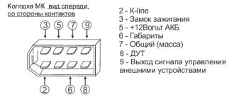
The following wires need to be connected to any on-board computer:
- Power supply +12 V.
- Power when the ignition is turned on to start the computer.
- Power that appears when the side lights are turned on. This will cause the BC display to go dark at night.
- Weight.
- Signal from the fuel level sensor. Some device modifications allow you not to connect this wire. Multitronics X140 calculates the remaining gasoline based on instantaneous consumption.
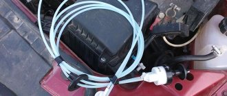
- Connect the diagnostic line from the K-Line controller.
For the first four points, a 4-pin block is used, specifically designed for connecting a BC. Accordingly, it is enough to connect it with the adapters that come with the computer. If this is not possible, then the first point is connected from the cigarette lighter, the second - from the ignition switch, 3 - from the cigarette lighter backlight. The ground is connected from the body of the same cigarette lighter.
It is very important that before any actions with electrical wiring you need to reset the negative terminal on the battery. This will protect you and your car from short circuits and other troubles. The signal from the fuel remaining sensor is taken from the gasoline level indicator. Its location can be found in accordance with the wiring diagram of the machine.
The diagnostic line (K-Line) is connected to the EURO-3 block in the seventh socket.
Basic and additional functions
On domestic VAZ 2110 cars, the on-board computer allows you to determine the air temperature outside, the speed of the car, the volume of gasoline in the tank and its average consumption. In addition, thanks to the BC, the driver will be able to find out how far the fuel in the tank will last. Depending on the model of the VAZ on-board computer, the device can show the operating parameters of the power unit and the voltage level in the car’s electrical circuit.
The main function performed by the State on-board computer is to identify combinations of errors in the components and systems of the vehicle, while connecting additional equipment is not necessary. In accordance with the instructions for the device, when the Check indicator appears on the BC screen or dashboard, you need to perform diagnostics of all systems. The received error codes are decrypted in accordance with the technical documentation; information on decoding the codes is also provided in this article. Another important function of the BC is the drying of the spark plugs, which greatly simplifies starting the engine, especially at low temperatures.
Message from BC about the need to replace the engine fluid
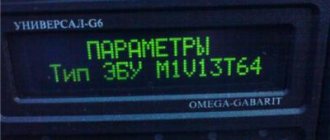
Depending on the VAZ 2110 computer model, the device can be additionally equipped with a tachometer, clock, voltmeter and even a calendar. IN practice, most BCs have volatile memory, as a result of which, when the battery is disconnected from the network, all error information will be saved. You can find many different BC models on sale, the most common of which are Gamma, Omega, Multitronics, and State 110. The latter option is optimally suited for the VAZ 2110, since models for cars are available with both an old and an improved dashboard.
The main functions of this bookmaker:
- the device provides the driver with data on fuel consumption, antifreeze temperature in the system, as well as mileage traveled;
- determining the distance for which the gasoline in the tank will last;
- providing information on car maintenance;
- demonstration of combinations of errors in engine operation;
- the ability to update the platform via the Network;
- another function is the presence of a plasmar necessary for warming up the spark plugs;
- there is a Fast and Furious option - its purpose is to reset the memory to standard settings;
- The Tropic function allows you to activate the fan when a certain engine temperature is reached.
It should be noted that these are not all the functions that a device for the domestic “ten” may have. On sale today you can find many different models of computers, the functionality of which can be expanded in accordance with the installed software. So, in general, the possibilities of a bookmaker depend on the model and, accordingly, on the financial capabilities of the buyer.
BC Gamma for “ten”
If you decide to purchase an on-board computer for a VAZ 2110, then it will be useful for you to find out what types can be found on sale:
- Universal BCs - such devices are designed for installation on any car; as a rule, they are used as an alternative to a rear view mirror. In some cases, universal devices can be installed on glass.
- Individual-type devices that are aimed at several car models at once. For example, domestic “eights”, “nines” and “tens” are one group, characterized by the presence of an old dashboard in the cabin.
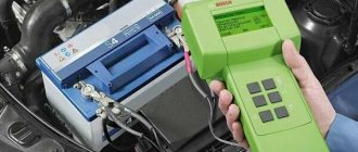
Car diagnostics
The appearance of a lit “Check Engine” lamp on the instrument cluster signals the driver that a problem has arisen in the vehicle’s electrical system. You need to understand that checking the vehicle yourself and at a service station can give different results. Special equipment available to professionals will allow more accurate detection of faults.
Self-diagnosis
On a VAZ 2115, the owner can do independent diagnostics and find out what errors are stored in the memory of the engine control unit. The procedure is carried out by calling up fault codes on the dashboard or using a diagnostic adapter.
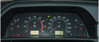
To carry out diagnostics on the electronic instrument panel, you must perform a certain sequence of actions:
- Sit in the driver's seat of the car, insert the key into the ignition and press the daily mileage reset button located on the instrument cluster.
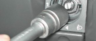
- Turn the lock key to the ignition switch position.
- Release the key, starting the self-diagnosis process. Visually, this will look like turning on the backlight, all signal lamps, possible symbols on the LCD screens and testing the instruments (the arrows will move across the entire scale in both directions).
- Press the key again and release. The second press displays the software version of the instrument cluster on the screen located under the speedometer (inscription like Uer x. x).
- Press the key again, after which the errors in the memory will be displayed on the screen.
Instrument cluster VAZ 2115, the button is located on the right side of the speedometer
The driver can perform self-diagnosis on the electromechanical panel and the “January-4” control unit according to the following sequence:
- Turn off the ignition.
- Open the diagnostic connector cover located on the center console.
- Connect contact B to the negative terminal of the battery (to the body). Contact A, connected to the engine crankcase, is suitable for this.
- Turn on the ignition. The “Check Engine” lamp will flash code 12, which means the diagnosis has begun. The light signals are given as follows - a long flash, then a pause (about 2 seconds), two short flashes, a long pause (about 3 seconds). Signal 12 is sent three times. If there is no signal, the diagnostic system is inactive or faulty. After this, the Check Engine light will flash and list the errors in memory. Each code is repeated three times. If there are no errors in the memory, code 12 will continue to be transmitted.
To read controller errors, a special K-Line adapter is used, which is connected to the diagnostic connector using a connector. This connector is located on the center console behind a plastic plug (below the cigarette lighter and ashtray). The adapter has a cord with a USB connector at the end that connects to any laptop. A special program for reading and resetting errors must be installed on the device (OpenDiagFree version 1.4 or 1.6).
The procedure for reading errors is quite simple, you need to:
- Check the level of process fluids.
- Open the connector cover and turn on the ignition.
- Connect the adapter or scanner to the diagnostic socket.
- Launch the software on the laptop.
- View available errors in the program dialog box.
- Decrypt the codes using the program interface or decryption table.
- Eliminate the causes of malfunctions and re-diagnostics.
On-board computer does not work on VAZ 2110
On-board computers on the VAZ- 2110 . Renault Csenic I phase 2 2001 faced a problem that the on-board computer does not show fuel consumption. connection On-board computer VAZ-2110 : instructions
Using on-board computers on a VAZ 2110
You can get a complete picture of the engine.
With its help, data is read from sensors and displayed. It’s easier while driving; the driver can find out at any time about fuel consumption, on -board , engine speed, and errors. But for everyone, even the most expensive and advanced on-board computer, there are pros and cons.
Connection diagram
The process of diagnosing an ECU using a special scanner.
Electronic control units of the VAZ-2110 are the main tool for controlling and automating most processes in the car. To adjust the software, they often resort to replacing the “brains” with more “flexible” ones and reflashing the ECU.
First of all, it is necessary to clarify several terms that will be required when considering questions about changing the electronic control unit:
- Wiring compatibility . To replace it, the connectors on the old ECU and the new one will need to match.
- Software is a predetermined algorithm that can change depending on the needs or desires of the motorist.
- The hardware component is the electronic control unit itself, boards or other components that allow the systems associated with the ECU to function normally.
For the VAZ-2110 family there were two types of connectors. So, for the “brains” January 5.1.x, Bosch M1.5.4, Bosch MP7.0, and VS 5.1 there was a 51-pin connector, but for January 7.2(+), Bosch M7.9.7(+) and M73 - 81 -pin.
That is, the interchangeability of control units is caused by the pinout of the unit.
ECU January 7.2.
Differences
Fundamental differences between 81-pin blocks and blocks of previous generations:
- Overall body dimensions and weight have been reduced.
- New, more modern connectors with improved connection reliability.
- The controllers have built-in switches, therefore, instead of ignition modules, ignition coils can be used, which increase the reliability of the ECM as a whole.
- There is no software or hardware compatibility with any of the previously released units.
Even electronic control units from the same manufacturer will differ significantly in pinout. Therefore, the interchangeability of the “brains” will depend on the number of connector pins. Also, it is worth understanding that the firmware will play a big role. When changing the ECU, the motorist will have to reflash the unit for the correct operation of all vehicle devices.
ECU January 5.1.
A very important nuance remains that the software of the control unit must be compatible and comply with the type of injection, as well as the toxic standards laid down by the manufacturer.
Assignment of contacts of ECU Bosch M1.5.4, MP7.0 and January-5.1
Pinout of 55-pin ECU.
Let's look at the pinout of control units with 55-pin “brains”:
| Bosch M1.5.4 (1411020 and 1411020-70) January 5.1.1 (71) | Bosch M1.5.4 (40/60) January-5.1 (41/61) January 5.1.2 (71) | Bosch MP7.0 | |
| 1 | Ignition 1-4 cylinders. | Ignition 1-4 cylinders. | Ignition 1-4 cylinders. |
| 2 | . | Ground ignition wire. | . |
| 3 | Fuel pump relay | Fuel pump relay | Fuel pump relay |
| 4 | Stepper motor PXX(A) | Stepper motor PXX(A) | Stepper motor PXX(A) |
| 5 | Canister purge valve. | Canister purge valve. | |
| 6 | Cooling fan relay | Cooling fan relay | Left fan relay (only on Nivas) |
| 7 | Air flow sensor input signal | Air flow sensor input signal | Air flow sensor input signal |
| 8 | . | Phase sensor input signal | Phase sensor input signal |
| 9 | Speed sensor | Speed sensor | Speed sensor |
| 10 | . | General. Oxygen sensor weight | Oxygen sensor weight |
| 11 | Knock sensor | Knock sensor | Knock sensor input 1 |
| 12 | Power supply for sensors. +5 | Power supply for sensors. +5 | Power supply for sensors. +5 |
| 13 | L-line | L-line | L-line |
| 14 | Weight of injectors | Weight of injectors | Weight of injectors. Power "ground" |
| 15 | Control of injectors 1-4 | Oxygen sensor heater | Check Engine Light |
| 16 | . | Injector 2 | Injector 3 |
| 17 | . | Recirculation valve | Injector 1 |
| 18 | Power supply +12V non-switchable | Power supply +12V non-switchable | Power supply +12V non-switchable |
| 19 | Common wire. Weight of electronics | Common wire. Weight of electronics | Common wire. Weight of electronics |
| 20 | Ignition 2-3 cylinders | Ignition 2-3 cylinders | |
| 21 | Stepper motor PXX© | Stepper motor PXX© | Ignition 2-3 cylinders |
| 22 | Check Engine Light | Check Engine Light | Stepper motor PXX(B) |
| 23 | . | Injector 1 | Air conditioner relay |
| 24 | Stepper motor weight | Weight of stepper motor output stages | Power grounding |
| 25 | Air conditioner relay | Air conditioner relay | . |
| 26 | Stepper motor PXX(B) | Stepper motor PXX(B) | Weight of sensors TPS, DTOZH, DMR |
| 27 | Ignition switch terminal 15 | Ignition switch terminal 15 | Ignition switch terminal 15 |
| 28 | . | Oxygen sensor input | Oxygen sensor input |
| 29 | Stepper motor PXX(D) | Stepper motor PXX(D) | Oxygen sensor 2 input signal |
| 30 | Weight of sensors MAF, DTOZH, DPS, DD, DPKV | Weight of sensors MAF, DTOZH, DPS, DD, DPKV | Knock sensor input 2 |
| 31 | . | Reserve output high current | Rough road sensor input signal |
| 32 | . | . | Fuel consumption signal |
| 33 | Control of injectors 2-3 | Oxygen sensor heater. | . |
| 34 | . | Injector 4 | Injector 4 |
| 35 | . | Injector 3 | Injector 2 |
| 36 | . | Exit. Intake pipe length control valve. | Main relay |
| 37 | Nutrition. +12V after the main relay | Nutrition. +12V after the main relay | Nutrition. +12V after the main relay |
| 38 | . | Low-current backup output | . |
| 39 | . | . | Stepper motor РХХ © |
| 40 | . | Reserve input discrete high | . |
| 41 | Request to turn on the air conditioner | Request to turn on the air conditioner | Oxygen sensor heater 2 |
| 42 | . | Reserve input discrete low | . |
| 43 | Signal to tachometer | Signal to tachometer | Signal to tachometer |
| 44 | CO - potentiometer | Air temperature sensor | . |
| 45 | Coolant temperature sensor | Coolant temperature sensor | Coolant temperature sensor |
| 46 | Main relay | Main relay | Cooling fan relay |
| 47 | Programming permission | Programming permission | Air conditioner request signal input |
| 48 | Crankshaft position sensor. Low level | Crankshaft position sensor. Low level | Crankshaft position sensor. Low level |
| 49 | Crankshaft position sensor.High level | Crankshaft position sensor.High level | Crankshaft position sensor.High level |
| 50 | . | Recirculation valve position sensor | Programming permission |
| 51 | . | Request to turn on the power steering | DC heater |
| 52 | . | Reserve input discrete low | . |
| 53 | Throttle position sensor | Throttle position sensor | Throttle position sensor |
| 54 | Fuel consumption signal | Fuel consumption signal | Stepper motor IAC (D) |
| 55 | K-line | K-line | K-line |
We recommend: Kia Ceed: pros and cons
Description of contacts ECU M7.9.7 / January 7.2
Let's look at the pinout of control units with 81-pin “brains”:
| № | Compound |
| 1 | 21114 - Not used / 21124 - Ignition coil 2 cylinders. |
| 2 | 21114 - Ignition 2-3. Control of the primary winding of the ignition coil, act. level is low. / 21124 — Ignition coil 3 cylinders. |
| 3 | Ignition circuit weight |
| 4 | 21114 - Not used / 21124 - Ignition coil 4 cylinders. |
| 5 | 21114 - Ignition 1-4. Control of the primary winding of the ignition coil, act. level is low. / 21124 - Ignition coil of cylinder 1. |
| 6 | Injector 2. Active level low |
| 7 | Injector 3. Active level low |
| 8 | Output to tachometer. |
| 9 | Not used |
| 10 | Fuel consumption signal |
| 11 | Not used |
| 12 | Battery, terminal 30 of the ignition switch. |
| 13 | Nutrition. Ignition switch terminal 15 |
| 14 | Main relay |
| 15 | Contact "A" DPKV |
| 16 | TPDZ |
| 17 | TPS mass / TPS mass, DND |
| 18 | Input - oxygen sensor |
| 19 | Input - knock sensor |
| 20 | Knock sensor weight |
| 21 | Not used |
| 22 | Not used |
| 23 | Not used |
| 24 | Not used |
| 25 | Bosch Only - High Current Output, Reserved |
| 26 | Bosch Only - High Current Output, Reserved |
| 27 | Injector 1. Active level low |
| 28 | Not used / DK2 heater control output |
| 29 | Not used / Engine cooling fan control output 2 |
| 30 | Not used |
| 31 | CE lamp, act. level low |
| 32 | Power supply TPDZ / Power supply TPDZ, DND |
| 33 | Power supply for mass air flow sensor |
| 34 | DPKV input, contact “B” |
| 35 | Weight of DTOZH / Weight of DTOZH, mass air flow sensor, 1 DC (UDK), 2 DC (DDK) |
| 36 | Mass of the mass air flow sensor |
| 37 | Signal input from mass air flow sensor |
| 38 | Not used |
| 39 | Signal input from DTOZH |
| 40 | Signal input from intake air temperature sensor |
| 41 | Not used |
| 42 | Not used / DND signal input |
| 43 | Not used |
| 44 | On-board voltage input at the main relay output |
| 45 | Phase sensor power output |
| 46 | Canister purge valve control output |
| 47 | Injector 4. Active level low |
| 48 | Oxygen sensor heater control output |
| 49 | Not used |
| 50 | Additional starter relay control output |
| 51 | Controller weight |
| 52 | Not used |
| 53 | Controller weight |
| 54 | Not used |
| 55 | Not used / Signal input DK2 (DDK) |
| 56 | Not used |
| 57 | Input for encoding calibration data options. The controller memory can contain 2 sets of calibration data; switching is performed by shorting to ground. |
| 58 | Not used |
| 59 | Speed sensor |
| 60 | Not used |
| 61 | Weight of output stages |
| 62 | Not used |
| 63 | On-board voltage input at the main relay output |
| 64 | Output “D” IAC |
| 65 | Output “C” IAC |
| 66 | Output “B” IAC |
| 67 | Output “A” IAC |
| 68 | Engine cooling fan relay control output, act. level - low |
| 69 | Air conditioner relay control output, act. level - low |
| 70 | Fuel pump relay control output, act. level - low |
| 71 | K-Line |
| 72 | Not used |
| 73 | Not used |
| 74 | Not used |
| 75 | Input request to turn on the air conditioner, act. level - high |
| 76 | Power steering request input, act. level - high |
| 77 | Not used |
| 78 | Not used |
| 79 | Phase sensor signal input |
| 80 | Weight of output stages |
| 81 | Not used |
Typical faults
The need for replacement, as a rule, arises in the event of malfunctions in the operation of the device. If the computer begins to show incorrect data, the cause of the problem may lie in the contacts. Usually the contacts come off as a result of off-road driving and frequent vibrations. In this case, the problem can be resolved by reconnecting the devices.
In some cases, incorrect data is caused by glitches. If this is the case, then you won’t be able to solve the problem on your own - only specialists with the necessary equipment can help. In practice, the bookmaker can be reflashed, that is, the software can be reinstalled. In the event that the demonstration of incorrect parameters is associated with damage to the electronics, then the only correct solution is to replace the BC. Usually in this case, if there is mechanical damage to the system elements, the on-board computer does not work, which is the reason for its replacement (the author of the video is the IZO)))LENTA channel).
What to do if the problem recurs
If you replaced the knock sensor and deregistered p0327 in the ECU, and the “Check engine” icon appears again, then the problem may be in the engine sensor itself. It needs to be checked. You will need a multimeter, which should be set to resistance measurement mode (ohmmeter). The minimum threshold value is 5 MΩ (operating alternating voltage: U= 0.5–3 V). If it shows below, then the sensor is defective. It is unprofitable to repair it, since a new one costs about 250 rubles.
Another reason: the DD is attached to the cylinder block with a bolt. But its crimping force is small, so the detonation signal is weak. Experts recommend using a pin instead of a bolt, and tightening the sensor with a nut. Then the risk of error p0327 is sharply reduced. In addition, you should make sure that the formation of a malfunction is not caused by: extraneous knocks, such as vibration of the pan protection or the clatter of hydraulic compensators, as well as poor-quality fuel or poor fastening of the engine to the cylinder block.
On a note. Experts recommend buying one of two brands of knock sensors. First original: AvtoVAZ number 21120–3855020–03–0. Second analogue: Bosch - 0 261 231 046.
What does the on-board computer notify?
- When the car is moving, a light comes on, indicating a malfunction of the power unit. It is possible that there really are problems with the engine. It's easy to notice by the sound. If the light is on, but the engine behaves normally, do not rush to go to a car service center. A common problem with the BC on the VAZ 2110 is a small short circuit. Carry out diagnostics - cheaply and effectively.
- Fuel consumption is too high, it has even exceeded the maximum limit of 12 liters. If such a problem is detected, it can only be solved by flashing the controller firmware. Doing this on your own is difficult and sometimes impossible. Trust exclusively highly qualified specialists.
How to drive a fuel-injected car correctly
Trip computer VAZ 2110
You can give some important tips for operating a car with an injector:
- Maintenance must be carried out on time.
- The vehicle should only be fueled with the recommended fuel from the manufacturer.
- Sound insulation is necessary, as the injector is quite loud.
- The body should be treated with anticorrosive.
Note: processing is necessary to prevent the body from corroding.
Functional purpose of the device
The development of the technical component of vehicles has led to an abundance of electronic and mechanical devices that control the operation of the car. Each of them reflects one or another indicator, which a person does not always have time to analyze. This is where the VAZ on-board computer will help, taking control of what is happening. In addition to monitoring the operation of vehicle systems, it will promptly inform the owner about a failure.
Another advantage is that the standard on-board computer analyzes the technical condition of the car within the specified parameters. In practice, this means that the driver can ask a question regarding the presence of components or assemblies whose performance exceeds the technical norm. Preventative analysis reduces the likelihood of downtime due to technical failure. The VAZ trip computer differs in the available options depending on the configuration:
- Carburetor is a budget option that does not have sufficiently wide functionality. Installation does not take much time, and operation is simple. It is difficult to find it on the market due to low demand among VAZ-2110 owners.
- Injection - there are various options on the market that take into account the needs of drivers. Among the main advantages is the ability to conduct in-depth diagnostics. For example, if the car does not start because the injector has failed, the system will notify you in advance. The cost of the on-board computer depends on the configuration.
- Universal - installation is carried out on a VAZ-2111, 10 or 12 without taking into account technical specifications. Installation is carried out behind the rear view mirror or windshield.
- Adapted - selected taking into account the make and model of the vehicle. Installation is carried out in a strictly designated place, which the instructions will help you find.
Useful tips
There are several additional recommendations that will help you connect and configure the on-board computer without unnecessary problems.
- If there is free space on the front console, it will be the best option for installing an on-board computer display.
- If you plan to install the device on the dashboard, then make sure in advance that it is easy to read information from it. The driver needs to take a quick glance at the screen. Therefore, when viewing the display, your eyes should not go too low or to the side. Otherwise you will be distracted from the road.
- Some models of trip computers provide the possibility of mounting on a dashboard using remote housings. Start from the comfort and rationality of this arrangement.
- Take a closer look at touch BCs. This is a modern solution that allows you to get rid of mechanical buttons. If you are used to using a tablet or smartphone, then operating a touchscreen computer in your car will seem much more familiar and convenient.
- The system unit of the device can be installed in any convenient place. But even here you should be extremely careful. It is not recommended to place it near a stove or air conditioner outlet. High humidity and temperature can disrupt the operation of the system unit and damage the equipment itself.
- Don’t rush to connect everything without first reading the instructions. Sometimes the installation seems extremely simple, since there are matching sockets, pins and inputs for wiring. But manufacturers don’t just include a diagram and instruction manual with the device. There may be some nuances, and if you miss them, at best you will have to redo everything all over again. In the worst case, you will need a new bookmaker.
- If the car does not have special connectors for installing an on-board computer, it would be correct to seek help from a trusted diagnostic center. An experienced electrician will tell you how best to get out of the situation, help you choose an adapter, or use another connection method.
- Once connected correctly, you need to perform several actions on the machine. Usually the instructions indicate that you need to start the engine, idle the engine and drive a few kilometers down the road. All this is done strictly according to the instructions and in the specified sequence. This way, the computer will automatically read the data from the machine’s sensors, save it and analyze it.
- Most model and universal BCs purchased for cars are configured automatically. Only some nuances need to be adjusted manually. They are always provided with detailed instructions that the manufacturer encloses with the device. All user settings are entered and saved. Therefore, you need to immediately select the parameters that you need. Decide in advance what exactly you want to see on the display.
The absence of a standard on-board computer on a car is not a death sentence at all. Current opportunities allow you to buy the device separately and connect it to the electronic control unit of your vehicle yourself.
Since most devices are configured automatically, the main task for the car owner will be the correct connection. Always refer to the manufacturer's instructions as this guide is the most accurate.
The dashboard of the VAZ-2115 has a pre-designed space for the subsequent installation of an on-board computer. In this case, if you need to install a control device in a car, then there is no need to change the design of the torpedo, but rather use a standard socket.
The on-board computer provides comprehensive information to the driver about the following indicators:
- Vehicle movement mode.
- Gasoline consumption.
- The state of the car's electrical network and so on.
In addition to information capabilities, such a device is capable of diagnosing the state of the internal combustion engine control system. Certain types of on-board vehicles can be installed on cars with carburetors. However, for everything to work, you will need to additionally install a number of sensors.
In the modification of the VAZ-2113, a computer is installed that interacts with the controller of the internal combustion engine control system. Its task is to process all incoming information and display the main indicators on the screen in an understandable form.
Automotive stores today sell a wide variety of such devices, which differ in their functionality and location in the car.
All functions of the device in question are divided into two parts:
- Informational.
- Diagnostic.
To enable the required operating mode, use seven buttons on the device panel:
- Pressing this button tells the computer that the ride has begun. The same element resets the accumulated information in memory.
- + and – are designed to adjust the values of various characteristics when the device is in setup mode, as well as to study information about the state of specific components of the car.
- In addition to display functions, the on-board computer can produce sound signals when the actual parameter values exceed the maximum permissible standards. This is a kind of emergency signal.
These are not all the functions of the device in question, but only the main capabilities. Next, we will look at the process of installing a computer in a car.
What allows you to control bookmaker
Judging by the instructions, the VAZ-2110 on-board computer has the following capabilities:
- Controls mileage.
- Displays the time and allows you to set the alarm.
- Shows outside air temperature.
- Displays the average fuel consumption.
- If necessary, shows the current flow rate.
These are just the basic capabilities that the on-board computer on the VAZ-2110 provides. Moreover, you can significantly increase the number of device functions by installing newer firmware.