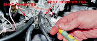
A design difference between most domestic cars produced in the last century is the need to manually adjust many parameters. The VAZ 2106 is no exception, to maintain it in good condition it is important to carry out timely maintenance of all systems, including periodic adjustment of the thermal clearances of the valves.
- Adjusting the valve clearances of the VAZ 2106
Reasons for adjusting the clearances - Frequency of adjustment and size of gaps
- Required Tools
- Procedure for adjusting valve clearances
Checking timing chain tension
- Video: procedure for checking timing chain tension
- The procedure for adjusting valve clearances on a VAZ 2106 with a micrometer
- Procedure for adjusting valve clearances with a feeler gauge
- Video: adjusting valve clearances on a VAZ 2106
- Signs of failure of valve stem seals
Video: replacing valve stem seals on a VAZ 2106
- Valve cover gasket replacement procedure
Video: replacing the valve cover gasket
We adjust the valves of the VAZ 2106, sequence table + adjustment video
Car owners of “classics” designed during the Soviet period often have to deal with the issue of repairing and tuning their car. Due to the high popularity and fairly strong density of cars on the roads of that time, some repair procedures and tuning operations remain quite relevant.
The design difference between classic cars and products of the modern automotive industry is the need to manually adjust many parameters.
Work order:
The valve adjustment procedure on the VAZ 2106 is necessary for a number of specific reasons. The main reason is the significant heating of the power unit during operation. The laws of physics state that during heating there is a linear increase in the size of solids.
One of the most important elements that require adjustment under operating conditions is the gas distribution mechanism. The key element of this mechanism is the valve.
Valves are usually divided into intake and exhaust; they are responsible for opening access for the penetration of the air-fuel mixture into the working combustion chamber through special windows in the cylinder head. They are also responsible for the release of exhaust gases.
At the point of contact of the valve, a gap is formed, which is usually called thermal. It is this gap that is subject to careful adjustment.
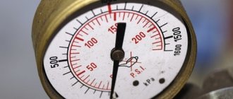
Valve adjustment gauges
The result of incorrect valve adjustment is an increase in fuel consumption and a noticeable decrease in the power characteristics of the power unit.
Why are guide bushings needed?
At the beginning and middle of the last century, car cylinder heads were made of cast iron, and the valves were simply inserted into precisely drilled holes. But subsequently, manufacturers abandoned cast iron heads due to their heavy weight and insufficient removal of excess heat, and they were replaced by lightweight cylinder heads made of aluminum alloys. These metals have excellent thermal conductivity, but have little resistance to wear from friction.
To solve the problem, a guide sleeve was invented - an intermediary between the soft alloy of the cylinder head and the steel valve stem, which constantly moves up and down during operation. Made of cast iron or special bronze, it is securely pressed into the cylinder head body, and the valve is inserted inside with minimal clearance.
The engine diagram shows the location of the guide bushings
The bushing itself is a hollow cylinder, made exactly to size for a specific car model. The outer surface is polished and smooth to the touch, and the inner surface has a spiral-shaped groove in the form of a thread. Motor oil moves along it, lubricating the valve axis and reducing friction. A shallow recess is made in the upper part of the guide part, into which a retaining ring is inserted.
Important point. The guide elements for the intake and exhaust groups of valves differ in design, although they may look the same in appearance (for example, parts for Russian VAZ 2108-09 cars). The difference is this: in the bushing for the exhaust tract, the oil groove is made along the entire length of the hole, and for the intake tract - only halfway. But products for the “classic” VAZ 2106 also differ in size; with the same diameter, the exhaust elements are longer than the inlet elements.
Bronze bushings for VAZ 2109 all look the same
Bushings perform the following functions:
- as the name implies, they direct the movement of the valve so that its plate is clearly aligned with the seat and fits tightly to it;
- take on the load from the friction force that occurs during the translational and reciprocal movement of the valve stem;
- the valve cup gets very hot in the combustion chamber, and the bushing transfers this heat to the aluminum alloy of the cylinder head;
- Thanks to a special groove, the part provides lubrication of rubbing surfaces.
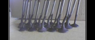
Cast iron parts of VAZ 2106 - intake bushings are shorter than exhaust bushings
When the element is pressed into the cylinder head hole, its upper part of smaller diameter protrudes several millimeters above the surface. This is necessary to install an oil seal on it (also known as a valve seal), which prevents lubricant from the upper part of the engine from entering the combustion chamber through the inner hole of the bushing.
This is what the protruding part looks like where the oil seal is put on
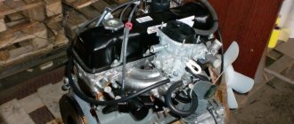
Preparation for work and disassembly
I would like to immediately note that this procedure requires time and is conditioned by an understanding of the process. There is a certain algorithm for implementing this task. To begin with, place your car on a level surface and provide free and well-lit access to the engine compartment.
The engine must be cooled and at ambient temperature.
Before starting the adjustment process, you need to prepare:
- a set of different wrenches in sizes “10”, “13”, “14”, “17”;
- 0.15 mm feeler gauge;
- key for turning the crankshaft;
- screwdrivers;
- spare valve cover gasket.
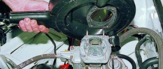
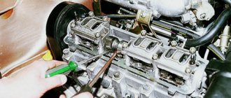
The disassembly process includes removing the air filter, disconnecting all pipes from the air filter cover, removing the choke cable, accelerator linkage and cylinder head cover.
It is advisable to remove the distributor cover so that it does not cause inconvenience during the adjustment process. There will be marks on the pulley and oil seal cover. The crankshaft must be turned until they coincide.
This position indicates that in the 4th cylinder the piston is on the compression stroke.
Preparatory work stage
First of all, you must wait until your engine has cooled down. Next, place the car on a flat surface and place chocks under the wheels. Now you can proceed to the immediate preparatory actions:
- dismantle the air filter cover and remove the filter itself;
- unscrew the fastening bolts and remove the filter housing, do not forget to disconnect all connected pipes before doing this;
- remove the choke cable (manual control of the air supply damper and disconnect the pipes that go to it);
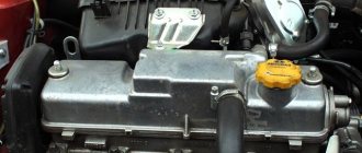
- unscrew the mounting bolts on the valve cover and then simply remove it;
- check the chain tension (if the chain is sagging or too tight, then adjust the tension immediately);
- remove the distributor cover;
- set the TDC of the piston in the fourth cylinder (this can be done correctly using the marks on the crankshaft, drive cover and camshaft gear).
To correctly install the piston in the desired position, take a suitable wrench, hook it onto the drive pulley bolt and begin to rotate the crankshaft until the marks match in the combination you need.
The procedure for carrying out the valve adjustment process
Table of the sequence of adjusting valve clearances on a VAZ 2106 car:
| Crank angle | Camshaft angle | Cylinder numbers | Adjustable valve numbers |
| 0° 180° 360° 540° | 0° 90° 180° 270° | 4 and 3 2 and 4 1 and 2 3 and 1 | 8 and 6 4 and 7 1 and 3 5 and 2 |
The valves must be adjusted according to a strictly defined sequence. The following data indicates the degree of rotation of the crankshaft to adjust one valve or the other:
- The initial position, when the marks coincide, makes it possible to adjust valves 6 and 8.
- Having turned the crankshaft 180 degrees, we adjust valves 4 and 7.
- Rotation 360 degrees provides access to work with valves 1 and 3.
- A 540 degree rotation allows you to adjust valves 5 and 2.
For convenience, car enthusiasts and craftsmen apply their own marks to the crankshaft pulley. Most often it is divided into two parts, leaving a mark opposite the one made at the factory.
The process of adjusting valves on a VAZ 2106, list and video
From this video, you will learn how to adjust valves for a VAZ 2106. Enjoy watching!
During the adjustment process, you should adhere to this algorithm:
- Having maintained the position set according to the marks, we check the gap on cams 8 and 6 of the camshaft. An important fact is that the gaps are calculated starting from the star mark, which is located closer to the windshield. From this cam we begin counting. Next, under the camshaft, slightly above the rocker itself, we place the dipstick. If the probe penetrates freely, then it is necessary to loosen the nut 17 of the rocker where the measurements take place. To avoid any problems with scrolling, you need to loosen the nut by 13. Next, tighten the nut by 17 and the gap is measured again. It is necessary to ensure that the probe, penetrating into the gap, does not bend, but at the same time fits into it quite tightly with a certain force. After achieving the desired result, you can begin adjusting the next cam.
- For approximately 6 strokes, use the key to rotate the engine shaft. The mark on the sprocket should be in the 9 o'clock position and aligned with the mark on the pulley. Next, we adjust cams 4 and 7. The adjustment process is identical to that described above.
- Then we rotate the shaft 180 degrees. The mark on the star is at the 6 o'clock position. The mark on the pulley must strictly coincide with it. In this position, cams 1 and 3 are adjusted.
- By turning the shaft so that the mark is at the 3 o'clock position, we will be able to adjust the 2nd and 5th cams.
- The last step is to crank the crankshaft with the starter, then check all adjustments and tighten the nuts. We reassemble all dismantled elements in the reverse order. If necessary, we replace the valve cover gasket during the assembly process.
Useful tips
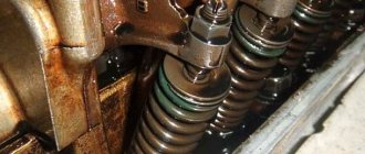
Particular attention should be paid to the timing chain before adjusting the valves. The chain must be installed correctly. The degree of tension should be carefully checked.
An uneven knocking sound in the area of the upper part of the valve cover is evidence that the thermal clearances of the valves are increased and their adjustment is necessary. To adjust and measure the gap, it is necessary to use special feeler gauges aimed at adjusting classic VAZ engines.
These probes are wider. Standard feeler gauges are quite narrow and are not able to cover the entire width of the gap in the area of the pressure arms and camshaft cams. This makes it impossible to determine the correct gap size.
In most cases, the cover accompanying the dipstick contains a valve adjustment diagram. It is presented and designed in the form of a table. A well-tuned engine on a VAZ model 2106 is a fairly reliable design.
Adjusted valves reduce engine noise, ensure maximum performance and fuel efficiency. To achieve and maintain the maximum performance indicators specified by the manufacturer, adjustments must be made at a preferable frequency of 15 thousand kilometers traveled.
Traffic warning signs. You can find out what these signs are on our website.
This article contains a rating of DVRs with two cameras.
Here you can read how to make panel tuning for a VAZ 2114.
Source
Purpose of VAZ 2106 engine valves
One of the most important systems that require adjustment during operation is the gas distribution mechanism (GDM). The design of this mechanism allows the fuel-air mixture to be supplied to the combustion chamber in a timely manner and exhaust gases to be removed from the engine cylinders.
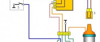
The timing belt includes the camshaft and crankshaft and the chain connecting them. Due to the timing mechanism, synchronous rotation of two shafts occurs, which, in turn, makes it possible to strictly observe the sequence of opening and closing valves in all cylinders.
The camshaft lobes act on special levers that push the valve stems. As a result, the valves open. As the camshaft rotates further, the cams return to their original position and the valves close.
Thus, the result of the operation of the gas distribution mechanism is the consistent and timely opening and closing of the valves.
There are two types of valves:
- Intake (open the fuel supply to the combustion chamber).
- Exhaust (provide removal of exhaust gases).
Disassembly and assembly of valve VAZ 2101, 2102
EXECUTION ORDER
1. Install the cylinder head on the board A.60335.
2. Disconnect the exhaust manifold and the intake manifold with the carburetor (at the same time the hot air intake is removed).
3. Disconnect the cooling jacket outlet pipe.
4. Disconnect the fluid drain pipe to the heater.
5. Remove the levers 11 (see Fig. Valve mechanism parts) of the valves, freeing them from the springs 12. Remove the springs of the levers.
Adjusting valve clearances on VAZ 2106
You can adjust the valve clearances of the VAZ 2106 yourself. To do this, you only need a standard set of plumbing tools and a few simple devices.
Reasons for adjusting clearances
The engine constantly operates at high temperatures. This leads to wear of its elements and a change in the size of the thermal clearances of the valves. External signs of incorrectly installed gaps are:
- the appearance of characteristic noise (knock) at idle;
- reduction in engine power and loss of dynamics during acceleration;
- increased fuel consumption;
- long-term operation of the vehicle without carrying out the clearance adjustment procedure.
Frequency of adjustment and size of gaps
The manufacturer recommends adjusting the thermal clearances of the VAZ 2106 valves every 30 thousand km, and checking their values every 10 thousand km. In addition, experts advise adjusting the gaps every time when dismantling the cylinder head (cylinder head) and replacing its gasket. If this is not done, the clearances of some valves will be reduced, while others will be increased. As a result, engine noise will increase, its power will decrease and fuel consumption will increase.
The gap size regulated by the automaker for intake and exhaust valves is 0.15 mm.
Required Tools
To adjust valve clearances, you will need the following tools and accessories:
- set of socket wrenches;
The dipstick cover usually shows the diagram and sequence of valve adjustment. However, a standard 0.15 mm thick feeler gauge cannot cover the entire width of the gap, so precise valve adjustment is not possible when using this tool. Moreover, the gap width gradually changes during operation due to wear of valves, cylinder head seats and other elements of the power unit. As a result, the adjustment accuracy is further reduced.
To more accurately set gaps, it is recommended to use a micrometer. In this case, the measurement results are practically independent of the condition and wear of engine elements.
Procedure for adjusting valve clearances
A special key is used to gradually rotate the crankshaft to a certain angle in order to sequentially adjust all valves. The numbering of valves, like cylinders, starts from the front of the engine, that is, from left to right.
The procedure for adjusting the valves is as follows:
- when the crankshaft is stationary, valves 8 and 6 are adjusted;
- when the crankshaft is turned 180 o, valves 7 and 4 are adjusted;
- when the crankshaft is turned 360 o, valves 3 and 1 are adjusted;
- When the crankshaft is turned by 540 o, valves 2 and 5 are adjusted.
You can also control the angle of rotation of the crankshaft by observing the movement of the distributor slider or camshaft. The only difference is that valves 7 and 4 are adjusted by turning by 90 o, and not by 180 o, as indicated above. The angle of subsequent turns should also be half as large - 180° instead of 360° and 270° instead of 540°. For convenience, marks can be applied to the distributor body.
Checking timing chain tension
Before setting valve clearances, you should check the timing chain tension and adjust it if necessary. As the vehicle is used, the chain gradually stretches. As a result:
- an unpleasant knock occurs when the engine is running;
- the chain wears out quickly;
- the chain jumps on the teeth of the camshaft sprocket, which leads to disruption of the timing phases.
Checking chain tension can be done in two ways:
- Open the hood and listen to the running engine. If there are extraneous noises that disappear when you briefly press the accelerator pedal, it can be stated that the chain is weakened.
- Remove the protective casing from the engine. We insert a screwdriver into the chain like a lever and try to bend the chain in at least two places where there is free space under it. The chain should not bend. A similar operation can be performed by hand. At the same time, it is not recommended to press hard on the chain to avoid damaging it.
When the chain is loosened, its tension is adjusted using a special tensioner.
Video: procedure for checking timing chain tension
The procedure for adjusting valve clearances on a VAZ 2106 with a micrometer
The algorithm for adjusting valve clearances with a micrometer is as follows:
- Place the car on a level surface and open the hood.
- Turn off the on-board power supply. To do this, disconnect the negative terminal of the battery.
Procedure for adjusting valve clearances with a feeler gauge
Adjusting the gaps with a feeler gauge is carried out similarly in the following order:
- By turning the crankshaft flywheel, we ensure that the marks of the camshaft sprocket and its bearing cap coincide. As a result, the piston of the fourth cylinder will rise to TDC, and it will be possible to adjust valves 6 and 8.
- We install a standard feeler gauge (0.15 mm) between the camshaft and valve rocker 8.
Video: adjusting valve clearances on a VAZ 2106
Valve stem seals
Oil seals (valve seals) are designed to seal the valve. They trap excess lubricant (motor oil), preventing it from entering the combustion chamber.
The mechanical pair in the cylinder head is the valve stem and its guide sleeve. Technologically, it is almost impossible to join these parts without a gap. Valve seals are used to seal the connection. A high-quality and serviceable cap should fit tightly on the valve stem and allow only the amount of oil to pass through that is necessary for normal operation of the system.
If earlier the caps were made of fluoroplastic, now their production uses special reinforced and oil-resistant rubber. The upper part of the cap is pressed against the valve stem by a special spring.
The market offers valve stem seals from various manufacturers and brands, differing in quality, reliability and durability.
After long-term operation of the engine, the oil seal may collapse due to:
- physical aging of the material from which it is made;
- loss of the original elasticity of rubber under the influence of oil and high temperature;
- material delamination.
This causes excess lubricant to enter the combustion chamber and increases oil consumption. Oil seals on domestic cars are usually replaced every 80 thousand kilometers. The last figure may increase significantly as a result of:
- use of caps made of modern high-quality materials;
- using high-quality original motor oil;
- preventing engine overheating;
- constant monitoring of the engine oil level.
Signs of failure of valve stem seals
The main signs of malfunction of valve seals on the VAZ 2106 are:
- increased oil consumption (more than one liter per thousand kilometers);
- light-colored exhaust gases;
- oil deposits on spark plugs;
- significant reduction in the dynamic characteristics of the engine;
- increase in fuel consumption.
Such problems can be solved by replacing the caps. It's quite easy to do it yourself.
Selection of valve stem seals
Until the end of the 80s, caps produced by the Kursk plant were installed on all domestic cars. They were not of high quality, since they could not withstand high temperatures, and they had to be changed every 30 thousand kilometers. Then a new rubber-like material (fluorine rubber) was developed, from which leading manufacturers began to make caps. The material from which they are made may differ in color, but its basis should be rubber (recycled or acrylate), which ensures the durability of the part.
The presence of impurities in the material of the caps leads to their rapid failure. This applies primarily to fakes. Therefore, when purchasing, you should first of all pay attention to the manufacturer and be able to identify original products. The cost and service life of caps from leading brands are approximately the same.
When replacing VAZ 2106 caps, we can recommend the products of the following companies:
- Elring is a German company that produces not only rubber caps, but also a number of other parts, and supplies its products to more than 140 countries.
- Glazer is a Spanish company with a rich history, producing caps that are certified and comply with ISO9001/QS9000 requirements.
- Reinz is a German company whose products experts recommend installing on an unworn valve-guide bushing pair.
- Goetze is a German company recognized by automakers around the world. Since 1987, Goetze has been a supplier of quality spare parts for cars and boats, including valve stem seals, manufactured using innovative technology.
- Payen and other manufacturers.
The quality of original domestic products is significantly inferior to foreign analogues. In any case, the choice remains with the car owner, his wishes and capabilities.
Replacing valve stem seals for VAZ 2106
To replace the caps you will need:
- special desiccant for valve crackers (fasteners);
The procedure for replacing valve stem seals is as follows:
- Remove the valve cover from the cylinder head.
- Remove the camshaft and rocker.
Video: replacing valve stem seals on a VAZ 2106
When do you need to change guides?
The main symptom indicating that the valve bushings have become unusable is increased engine oil consumption. When the rod has lateral free play (play), the valve stem seals are no longer able to prevent the penetration of lubricant into the cylinders from the upper engine compartment, where the camshaft is located. It flows into the increased gap between the valve stem and the inner diameter of the bushing and freely enters the combustion chamber.
Blue smoke coming out of the exhaust is a sign of oil combustion.
Signs of oil consumption due to problems with the guides are:
- bluish smoke from the exhaust pipe from escaping combustion products of lubricant that constantly enters the cylinders;
- the car practically does not lose in dynamics, but smokes a fair amount;
- light “fluffy” carbon deposits on the spark plug electrodes;
- liquid oil is observed on the skirts and threaded parts of the spark plugs.
Advice. By the carbon deposits on the spark plugs, you can determine the cylinder into which the largest amount of lubricant gets. This will be useful for performing diagnostics.
This is oil deposits on the spark plug.
Since oil can also penetrate into the chambers due to the fault of the cylinder-piston group, it is necessary to carry out diagnostics to accurately determine the malfunction. As an example, it is proposed to take the popular VAZ 2106 car:
- Measure the compression in the cylinders. The goal is to ensure that the piston rings are in good technical condition.
- Remove the valve cover, loosen the chain and unscrew the camshaft gear, first aligning the marks.
- Dismantle the camshaft along with the bed and remove the rocker arms. Unlock the valve springs of the cylinder whose spark plug is more heavily covered with carbon deposits.
- Carefully remove the oil seal and try to rock the rod sideways with your hand, while moving it up and down.
To feel the play, the valve must be pulled out by the stem and rocked to the sides
If there is play, you can safely continue disassembly, since to replace the bushings you need to remove the cylinder head. If you have no doubts, check the other valves, the picture should be approximately the same.
Replacing the valve cover gasket
The need to dismantle the cylinder head cover arises in the following situations:
- when tensioning the chain in the engine;
- when replacing the valve cover gasket;
- when adjusting valves;
- when replacing other engine parts.
The process is simple and will not take much time with minimal plumbing skills. To do this you will need:
- heads for 8 and 10;
- extension for keys;
- crank or ratchet;
- pliers.
Valve cover gasket replacement procedure
The valve cover gasket is changed as follows:
- Unscrew the three nuts and remove the cover from the metal air filter housing.
- Remove the air filter from the housing.
- Unscrew the four nuts securing the filter housing to the top of the carburetor.
After replacing the gasket, assembly is performed in the reverse order.
Video: replacing the valve cover gasket
Procedure for tightening the nuts on the valve cover
The nuts on the valve cover should be tightened very carefully in a strictly defined sequence, as excessive force can strip the threads on the studs. First you need to tighten the nuts in the middle of the cover, and then gradually move to its edges.
Correctly and timely adjusted valves will allow the owner of a VAZ 2106 to avoid much more serious problems. You can do this yourself, having a standard set of tools and devices and carefully studying the recommendations of professionals.
Source