Ground points in the car interior
- GND7 – ECU ground
- GND8 – ground on the engine shield
- GND6 – ground above the fuse box
- GND5 – tunnel mass
At the rear of the car, the “grounds” are located near the lights:
Removing the instrument panel
We carry out work to replace the instrument panel, panel wiring harness and elements of the heating and ventilation system. Disconnect the wire terminal from the negative terminal of the battery. We remove the steering column switches (see “Removing the steering column switches, switch connector and spiral cable drum device”). Remove the cover of the fuse box (see “Replacing fuses and relays”). We disconnect the wire blocks from the ignition switch (see “Removing the ignition switch, replacing the contact group and immobilizer coil”). We disconnect the wire blocks from the electric power steering control unit (see “Removing the steering column”). Remove the floor tunnel lining (see “Removing the floor tunnel lining”). Overcoming the resistance of plastic latches...
...remove the left front pillar trim. Similarly, remove the upholstery of the right front pillar.
Using the blade of a slotted screwdriver, placing soft material under it, pry off the glass blower nozzle of the left door. Similarly, remove the blower nozzle on the right side.
Using a 10mm socket, unscrew the nut for the upper fastening of the instrument panel, located in the cavity under the door glass blower nozzle. Similarly, unscrew the nut on the right side.
Using a 10mm socket, unscrew the bolt securing the ground wire ends of the instrument panel.
We disconnect the wiring harness connectors of the instrument panel from the wiring harness connectors located on the bracket above the fuse mounting block...
...and the wire block located on the right end of the bracket.
Disconnect the engine control wiring harness block from the instrument panel wiring harness block...
...and use a 10mm head to unscrew the nut securing the end of the ground wire. We disconnect the middle block of the instrument panel wiring harness from the electrical accessories control unit (see “Removing the electrical accessories remote control system controller”).
Disconnect the wiring harness from the airbag control unit.
Using a Phillips screwdriver, unscrew the four screws securing the instrument panel trim... ...and remove the trim.
Using pliers with narrow jaws, squeeze the clamps and disconnect the clamp securing the wiring harness from the bracket on the steering column.
Using a Phillips screwdriver, unscrew the screw on the side fastening of the instrument panel. Similarly, unscrew the screw on the right side of the instrument panel. Opening the glove box...
...and in the cavity behind it, use a Phillips screwdriver to unscrew the self-tapping screw securing the instrument panel.
Use a Phillips screwdriver to unscrew the console fastening screw on the left, and similarly on the right.
We remove the instrument panel from the car interior. We install the instrument panel in the reverse order.
Removing and installing a torpedo on a Priora
How to remove the dashboard on this car? Quite simple if you follow the instructions. On a Lada Priora, removing the torpedo will not be difficult. This must be done if you need to install a soundproofing shield, or paint the panel itself, or replace it.
You will need tools such as screwdrivers (flat and Phillips), pliers (specifically with narrow jaws) and a number 10 head. To remove the dashboard on a Priora, you need to disconnect the negative terminal from the battery. The work must be carried out carefully so that the instrument panel lighting is not affected. After this, you can remove the steering column switches.
Now the surface of the safety block on the Priora is disconnected. To do this, you need to rotate the locks of this cover 90 degrees, and then remove the latches from the safety block on the Priora. Now you need to carefully remove all the wires from the ignition switch. Then the instrument cluster is carefully removed. After this, the center floor tunnel is released. It is necessary to remove the cables from the power steering on the Priora.
Next, you need to perform these actions in turn. Loosen the latches and remove the pillar upholstery on the left side. Use the same steps to remove the upholstery on the right side of the Priora. Then the glass blower is removed from the right and left sides. It is better to use a screwdriver with a soft cloth underneath it to avoid damage.
To remove the torpedo on the Priora, you need to further unscrew the nuts, which are the upper fasteners of the torpedo. These nuts are located on either side of the blower nozzle, which is already disconnected. Then you need to remove the tips from the torpedo. Be sure to further remove the blocks with cables that connect the dashboard.
These pads are located near the bracket. All pads are removed one by one. It is necessary to remove not only the side pads, but also the central one. To do this, unscrew the fastening nut from the controller near the center console.
On the other hand, the fasteners also need to be disconnected. Now you need to remove the controller from the torpedo. After this, you can squeeze the center pad latches and pull it out. You need to disconnect its two connectors along with the cables. Next, the harness near the bracket is released. You need to be careful, because... The dashboard lighting should not be damaged.
Now you need to unscrew the screws in the side mount of the torpedo. Phillips screwdrivers are used for this. Similarly, on the other side, the fastenings are disconnected. You need to carefully monitor navigation devices. Now you should open the glove box (glove compartment). There you can also unscrew the torpedo screw. Then the side screws of the console are removed. After this, you need to carefully remove the torpedo on the Priora. If it is necessary to reinstall the torpedo, then all steps are performed in the reverse order.
What is engine demining?
Structurally, the car has a developed electrical system, in which the serviceability and accuracy of the controllers, various sensors and many other electrical devices depend on the mass. The electrical ground (minus) is connected from the battery to the car body. The body is conventionally a return wire, forming a closed electrical circuit.
The movement of electrons along the circuit is initiated by the battery, and the body acts as a conductor of negative charge for return via the negative terminal. For this reason, the metal body of a car is called car body. In this case, engine demining should be understood as a number of improvements that involve additional connection of the most powerful consumers of electricity in the car to ground.
Engine ground location
Engine mass location
In order to operate a car and carry out repair operations on it, you need to know where the mass is located. Thus, almost all devices and components of the VAZ-2114 require electrical power, and the most powerful consumers are the starter and engine .
Few people know where the ground is located on the engine, since to carry out repair operations it is enough to remove the “minus terminal” from the battery. But, during complete dismantling, and after installing the motor, you need to know where to attach the power.
So, the mass of the body is located on the metal mudguard near the battery.
Location of mass on the body
But, the negative branch consists of 2 wires: thick and thin . So, it is the thick wire that goes to the ground of the body, and the thin one to the closure of the engine circuit. Of course, not all motorists know where it goes.
The negative wire of the VAZ-2114 engine is located on the cylinder head and is attached to the tightening bolts that hold the cylinder head plugs.
Location of the VAZ-2114 engine mass
Where is the mass of the Prior engine
Prior's father has a sedan from the end of 2009, 1.6l 16kl engine, mileage 42,200 km.
The configuration with power steering for that year is the simplest, one might say, if you don’t count the Prior with an 8kL engine. I decided to check the charging during the week! He came home from work, I connected the tester to the battery terminals. At XX, warmed up: 13.72V; at XX with consumers turned on, which he often uses in winter (dimensions with a neighbor, stove on 1st, heated rear window and mirrors, radio): 12.6V. Those. in the first case it is low, and in the second it is too much.
I tightened the alternator belt, and at the same time I thought, let me take on: the ground on the power steering reservoir bracket:
weight on the engine:
ground from the “-” terminal of the battery to the body:
ground from the “-” terminal of the battery to the engine:
I didn’t touch the other masses, there’s no need and no point!
All these masses and their studs were cleaned of the slightest dirt, cleaned if necessary, lubricated and well tightened. Before this, I did not forget to remove the terminals from the battery, wiped the entire battery, cleaned and lubricated the terminals, also removed the wires hanging on them and also cleaned and stripped if necessary and lubricated, everything was tightened well! There was no result, and there was no time to mess around!
I came to the dacha over the weekend and decided to finish it. I removed the “-” terminal from the battery. pulled out and inserted two generator power circuit fuses F4, F6 (60 A), in the main fuse block:
weight was transferred from the engine (thermostat) to the gearbox stud: from here: here (at the very bottom in the photo):
Result: At idle, warmed up: 13.85V; at XX with the consumers turned on, which he often uses in winter (dimensions with the neighbor, stove on the 1st, heated rear window and mirrors, radio): 13.1V.
Source
Does the on-board voltage drop below 14 V, and the engine shudders when the cooling fan turns on? Check the reliability of the ground connections on the engine and car body. It is also recommended to modify the design by installing additional “mass” from the battery.
ECU weight
How the mass of the ECU works, how to check the mass of the ECU, what problems may arise and how to modify it to avoid troubles in the future.
It is these very important questions that we will address on this page.
A reliable ECU ground is very important for the proper operation of the engine management system and the engine as a whole.
It would seem to be a primitive and reliable design that can serve well for years. But in reality this is far from the case.
It is very difficult to list all the possible problems that can arise due to poor ECU mass, since it can affect anything. But the main problems can be divided into two points:
- Incorrect collection of information from engine control system sensors. Personally, I had to deal with incorrect MAP sensor readings. It gave inflated barometric pressure readings precisely because of the poor weight of the ECU.
- Since almost all modern engine control units are able to adapt to real operating conditions, as a result of incorrect collection of information from sensors, adaptation leads to engine malfunctions. This is why for many, after resetting the adaptations, the engine begins to work much better. But then the problems return as the ECU adapts again. And again this does not happen quite adequately.
Additional ECU weight
We will try to do this within the budget. Therefore, I immediately want to dissuade you from adding additional mass to the ECU using special wires for mass and all kinds of copper braids. And I see three reasons for this:
Therefore, I think that the ideal option is a regular wire with a cross-section of approximately 4 sq. mm. Actually, this is the path I followed.
Using the example of a Chevrolet Lacetti with a Sirius D42 control unit, we will need:
The whole thing cost 30 UAH.
Disconnect the negative terminal of the battery
Now you need to use a 12 mm wrench to unscrew the nut securing the negative wires to the starter bolt
This is not as difficult to do as many people think. Yes, everything needs to be done by touch, but it is quite possible. I have unscrewed this nut a huge number of times, so I can do it in one minute without any problems. Believe me, the eyes are afraid, but the hands do! Or rather, in our case, the eyes don’t see, but the hands do
We lean towards the engine from the battery side, extend our hand to the starter, feel for the nut under which the wires are located, loosen it with a wrench, and then unscrew it with your fingers
Remove the nut, then the engraver and take out the wires towards you
We clean them and add our additional ground wire to them
Now we also install the wires, engraver by touch and tighten the nut
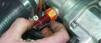
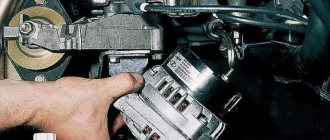
Let's move on to the ECU. Unscrew any ECU mounting nut with a 10 mm wrench. I chose the top one to make it easier to maintain in the future.
Cleaning it up. We stretch the wire to this place and tighten the nut
Now we make a control measurement of the voltage drop from the engine to the ECU, as in the previous article at the link above
As you can see, everything has returned to normal. The goal was achieved, which means all the manipulations were not in vain.
It took me 30 UAH for everything. and half an hour.
I hope the information will be useful to you. Express your opinion in the comments.
Has anyone done additional masses for the generator and battery and will it be any good?
Has anyone done additional weights on the generator and battery and will it be any good??
Good evening ladies and gentlemen
by Adminrive · Published 09/08/2014
I haven’t looked in stores for so long
by Adminrive · Published 12/29/2014
Has anyone struggled with the gasoline vapor recovery system?
by Adminrive · Published 01/27/2017
- Comments 13
- Pingbacks 0
Will. Plus duplicate.
If you do, you won't regret it! Buy kg 35 or 25
Of course it will be helpful. 50 kV is better to take the wire straight away.
will be stretched + from the genes with a cable of 25 kg and weight, it sags much less when the windshield heating is turned on, previously there was a drawdown of 1 volt
How to maintain ground attachment points
A bad “ground” leads to large-scale failures or “glitches” of the vehicle’s electrical equipment. To prevent this, you should regularly service the attachment points of the “mass”:
- Unscrew the nut and clean the contact surface of the stud with fine sandpaper;
- Check the condition of the wire tips to ensure they are securely crimped and that there is no breakage or oxidation. Clean with sandpaper or replace with new ones;
- Remove dirt with a cloth. Place the wires on the stud, install the washer on top, and then the Grover washer. After this, tighten the nut well (it is better to use new galvanized fasteners);
- Lubricate with Litol or spray with silicone grease.
Let us remind you that we previously published background information for passing the Lada Granta/Kalina maintenance (articles and refueling volumes).
I decided to check all the masses, clean the connections and duplicate + and - to the battery. Let's start with something interesting - Cleansing the masses. I found only 4. We also find them, take sandpaper 200 - 400 and go:
— The first and most important one is located near the battery, behind the headlight. The backup KG-35 was attached there. — The second one is on the head near the air vent — The third one is behind the left headlight — The fourth one is on the ECU mounting bracket
Cleaned everything up and tightened it securely.
The duplicate KG-35 goes from the gene to the battery (+) and from the body to the battery (-) This did not fix the problem with the sensor (I will calibrate it tomorrow) But the voltage has increased, engine starting has become faster and... it seems that the car drove a little more fun
How to maintain vehicle ground points
Poor contact will affect the operation of electrical appliances. Most often these are large-scale failures or “glitches” of the vehicle’s electrical equipment. To prevent this, you should monitor the condition of the mass attachment points:
- Unscrew the nut and clean the contact surface of the stud with fine sandpaper;
- Check the condition of the wire tips to ensure they are securely crimped and that there is no breakage or oxidation. Clean with sandpaper or replace with new ones;
- Remove dirt with a cloth. Place the wires on the stud, install the washer on top, and then the Grover washer. After this, tighten the nut well (it is better to use new galvanized fasteners);
- Lubricate with Litol or spray with silicone grease.
Have you ever encountered problems with your car's electrical system when the cause was a bad ground? Let us remind you that other operating instructions for Vesta can be found in this category or in the contents.
I decided to check all the masses, clean the connections and duplicate + and - to the battery. Let's start with something interesting - Cleansing the masses. I found only 4. We also find them, take sandpaper 200 - 400 and go:
— The first and most important one is located near the battery, behind the headlight. The backup KG-35 was attached there. — The second one is on the head near the air vent — The third one is behind the left headlight — The fourth one is on the ECU mounting bracket
Cleaned everything up and tightened it securely.
The duplicate KG-35 goes from the gene to the battery (+) and from the body to the battery (-) This did not fix the problem with the sensor (I will calibrate it tomorrow) But the voltage has increased, engine starting has become faster and... it seems that the car drove a little more fun
Tags: VAZ, Priora, masses, duplication of masses
Comments 43
handsome, everything is correct and neat, when you do everything carefully and as needed and the car runs normally, but when the servicemen do nothing, then you get into trouble and negative emotions
It is necessary to duplicate the nutrition of the ChYa too. All consumers are powered from there, and only 4 or 6 kV of wire goes to it.
Explain to the person falling asleep what Ch.Ya is?
Black box with data.
Explain to the person falling asleep what Ch.Ya is?
The fuse box on the chisels is black with a cover. That's why the Black Box -)
Yes, I wonder what program the 3D models are made in?
Idk, true. they sent them to me
What did you use to crimp the terminals?
Pliers with a force increasing mechanism
I don't know what they are called. In short, you put a little pressure on them, but they squeeze with mad effort. There are two rods inside and a stiff spring. externally they look like a gas wrench
aaa) I understand) I also plan to carry out such a procedure)
here is the link below, the man threw one to one like mine
I don't know what they are called. In short, you put a little pressure on them, but they squeeze with mad effort. There are two rods inside and a stiff spring. externally they look like a gas wrench
It's called a manual hydraulic press.
yeah, pneumatic there's a stupid spring
I don't know what they are called. In short, you put a little pressure on them, but they squeeze with mad effort. There are two rods inside and a stiff spring. externally they look like a gas wrench
Yes, exactly like that, only black!
correctly called “pins”, they can still be pinched and secured)
well, the fact that it was more fun is most likely self-hypnosis) but in general it did a useful job)
Self-hypnosis is when you install the spider and the firmware. And you think “ooh, the car is rushing, I installed a spider.” And then I didn’t even allow the thought that it would be better to drive. I just felt
Why copy them?
As soon as you hit the darts as quickly as possible, the voltage will increase. This is mainly needed by those who are serious about music. axle like this
We need to do the same, are these wires sold?
yes, these are welding wires
We need to do the same, are these wires sold?
Yes. KG-35. You only need 2 meters. Either in welding or electrical goods
Ah, I see, thanks.
Tell me, where do you get these pictures from?
Someone posted it on LPK in the comments
what is the program in the last pictures, bro? please tell me
did you put it on + from the battery to the gene?
but this is very in vain, when improving something, make sure that you don’t worsen anything, as a result of a fire you can lose the car as a whole
+1 when the diode bridge shorted out, this wire burned out and the fire stopped, and the KG-35 will burn out for a long time)
That’s right, I’m not saying that God forbid there is an accident and this wire gets crushed, the probability of a fire is very high
at least 1 near the battery. The other day I did the same thing as you. I only had 1 prev. I'll put up a second one a little later. I'll take a photo tomorrow and post it
there will be a loss of at least 0.1V
My tester shows a loss of 0.02-0.05V.
did you put it on + from the battery to the gene?
Greetings. Tell me more about PRES, as I understand it, you are talking about fuses, so which one and what rating should I put in the cut of this cable? I also have duplicated “-” and “+”, I’m also puzzled by the easy possibility of getting burned, and I’m surprised why there isn’t some kind of protection... but since VAZ came up with this, there was nowhere to go at that time. In general. I’ll be glad for a link or something similar, of course, I’ll google it myself when I have time. Because the topic is important.
look at my blog. what wire do you have?
I looked. Is the fuse located opposite the common wire for the generator and starter? That is, without a fuse, the current will not flow anywhere? What's the denomination? There is an idea that the currents to the starter are so high that there should be a “powerful” fuse, but there may be too much of it, say, when a narrow wire that goes to the generator is shorted and it turns out to be an “Ilyich wire”. I replaced both + and - with “native” ones for the model, at least that’s what it said on the price tag. They turned out to be short, I realized this by laying them and comparing them with the old ones that the previous owner installed. Seeing how unreliable all this is, and having read a lot of stories about bad mass, etc. I decided to let the old wires run in parallel, stripping and re-crimping them. In addition, the old ground wire was useful for connecting the generator ground to the housing. I would like to show everything in the photo, but alas, I don’t get around to it, as a rule, I do it first, and then I think that it was worth making a photoset of the process, although it’s not a good idea to dirty the phone =( But it worked out, I think honestly ^^)
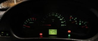
2110 2111 2112 Arrows jump on the instrument panel, the dashboard does not work
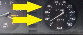
The situation looked like this: the engine is running, the engine is heating up, and the moment the cooling fan turns on, the arrow indicating the engine temperature jumps an order of magnitude higher. The car owner tried to change the engine temperature sensor, which takes readings for the instrument panel! Please note there are two of them, one for the shield and the other for the engine control unit. So the replacement did not lead to anything, everything remained as it was.
In the photo the arrow indicates the sensor that works for the instrument panel
My searches led me to the conclusion that this car is one continuous “bad mass.” I tried for a long time to determine the weak point, there was some kind of voltage loss at each contact, in the end everything worked fine only when I freaked out and attached the crocodiles for lighting, one to the other engine into the cabin to ground only after such a maneuver did the differences balance out and the sensor readings stopped jumping with the appearance of load.
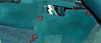
I got out of the situation by throwing an additional wire that connected the ground of the engine and the sensors on the instrument panel. The mass on the instrument panel is screwed behind the socket near the driver’s right foot.
This is also a sore spot, often it unscrews and the instrument panel does not work at all!
Without departing from the topic, I had a case when the interior air blower in a car did not work, the reason also turned out to be a mass, only that mass was located near the mounting block and on the left side under the inner trim
So, if you have similar symptoms, I recommend checking the weight of your car first, given that this is a very common problem with these cars.
Weight of ECU VAZ 21124
I came across an article by McSystem. Actually, here it is below
In January - about Januarys. Again and in detail about the ECM-ECU masses
One of the rather serious problems affecting the stable operation of engines controlled by the January ECU (7.2, 7.2+, M73, 7.9.7) is the “mass problem” of the ECM. Moreover, the point is not so much in bad (or uncrimped) contacts and their fastenings, but rather in the rather incorrect wiring of the ECM harness itself. And the solution is not in “pulling a fancy cable (KG-25 or 50)” to the ECU. Therefore, this material will be devoted to a technically competent approach to solving this problem. What is described below is a kind of compilation, or an attempt to “chew” what has been published more than once, in particular on ChipTuner.ru, and to convey to readers the specifics of solving this problem. The articles by I.N. turned out to be the most complete and informative. Skrydlova, (aka Aktuator) “About the masses”, “MASS: AN UNEXHAUSTABLE SOURCE OF GLITCHES” “ONCE AGAIN ABOUT THE MASSES” ©Oleg Bratkov. Many years ago, having read and comprehended what was written, I implemented it on my typewriter. I completely agree with the conclusion of the author (aka Aktuator): “All the assurances of AVTOVAZ OJSC about improving the quality of electrical connections in manufactured vehicles are not worth a penny. In most cases, it is possible to achieve normal operation of the engine under the control of the ECM I 7.9.7 and January 7.2 only by carrying out additional, and not accepted by the manufacturer as a warranty, work to change the electrical circuit of the car.”
So, on to the topic! Classic ECM 21124 with ECU January 7.2(+) or M7.9.7 Electrical connection diagram of ECM EURO-2 M7.9.7, January 7.2 LADA 2110 with engine 21124. 21124-1411020-30, 21124-1411020-31.32
Fig. 1 ECM 21124 January 7.2, M7.9.7 Noticed, often described and characteristic problems - unstable idle speed, freezing speed, “jerking” of the engine at start and operation of the cooling fan, unreasonable jumps in the electrical parameters of the ECM during diagnostics. And this is not the entire list. And the whole problem is a rather incorrect wiring of the harness masses, not in relation to the body, but to the ECU. Therefore, in this article you will not see recommendations for tightening the “hoses” of additional mass to the ECU, due to its complete uselessness. This is not a newfangled “razmasovka” or “razminusovka”... Don’t get your hopes up!
The main idea voiced by the authors is that the wiring of the power lines of the ECU and fan and low-current sensor masses is fundamentally incorrect. Rice. 12
Fig.2 Ground connections of the ECM. S6, S7, S8
The sensors must be connected to the ground bus of the ECU board and not have contact with the body! There should be no flow of pulsed and direct currents of the ECU and IM in the sensor mass circuit. And the ECU is securely connected to the body. The rationale is to eliminate the influence of ECU currents (pulse and constant) and fan current on the reliability of sensor readings. Classic approach with data collection and processing systems! But not from AvtoVAZ designers, as usual... Now, in order
Fig. 3 Masses according to AvtoVAZ, or how not to do it
1. The ECU masses are combined into three crimps S6, S7, S8, which are combined with each other and TWO bends are already made from them to the body studs B3, B4. 2. A switched minus fan with a rated current of 12A is connected to S6, and at the peak at start - all 20A! ! ! Which in itself is terrible! 3. All this is connected (screwed) to the ECU bracket, which in turn is very flimsily connected to the body. The engine ECM consists of sensors and actuators (AM). Sensors can be easily divided into analog and discrete. Analogue – mass air flow sensor, air pressure sensor, diesel sensor, DD. The output signal of these sensors is a voltage in a certain small range, usually 0 - 5V. For this group, any (even small) interference has a serious impact on the result. Discrete ones - DC (to some approximation), DF, DS (Speed Sensor) - are less critical to interference, because the output signal has two fixed levels high and low, and intermediate levels are not interesting to the ECU. Actuators - ignition coils, injectors, canister valve, DC heating, IAC, relays and other sources of large pulsed and direct currents along the negative (mass) bus of the ECU. To understand what the developers were up to, let’s look at the diagram in Fig. 3 – this is a fragment of the main ECM diagram in expanded form. It immediately catches your eye - the masses of the most sensitive and responsible sensors, mass air flow sensors and diesel fuel sensors, are wired, although there are separate pins for them, 36 and 35, respectively. For what? Silence in response! S6-S7-S8 are connected by jumpers, which makes the situation even worse.
Fig.4 Equivalent circuit in drain
A little theoretical background. Note - the resistance of the ECU connection lines has very real values and consists of the actual resistance of the wire, the transition resistance of the contact in the connector, terminal, etc. And the dimension of these quantities is milliOhms (1000 mOhm = 1 Ohm). In the diagram this is indicated as an equivalent resistor Rm, Rm1, Rm2. For reference: Resistance of 1 m of copper wire with sections 0.35 mm² - 45 mOhm, 0.5 mm² - 35 mOhm, 0.75 mm² - 25 mOhm. Well, there are no “zero resistance wires”! (Whoever managed to buy them, please remain silent)
When the ECU is operating, the current consumption of the ECU itself consists of the consumption currents of the ECU itself and its IM, especially the coils and injectors. Its pulse component reaches 10A, its constant component is about 1.5-2.5A. This current flows through the “mass terminals” of the ECU, “ECU ground” and “sensor ground,” which is fundamentally wrong. Fig.4 At very real resistances Rm, a voltage drop is formed between the connection point to the body and the negative bus (housing) of the ECU - Ucm1. In addition, the flowing current creates a bias voltage drop Ucm2 between the negative bus (housing) of the ECU and the connection point of the sensors. This tension is the root cause of all problems! It is summed with the useful voltage coming from the sensor and enters the measuring unit of the ECU - ADC (Analog-to-Digital Converter). Umeas = Usensor + Ucm2 And then the program processes the already digitized “false” result. With all the ensuing consequences. That is, the problem is not so much the reliability of connecting the ECU to the body, but the incorrect distribution of masses in the harness.
Engine demining and signs of poor grounding
An electrical circuit needs a good ground to function properly. Many people ask - why is engine demining necessary? The answer is - poor electrical grounding can affect one or more electrical systems, because it forces the current to look for other simpler paths. This can cause all sorts of problems with lights, sensors, modules and other electrical and electronic components, all of the above is also true to answer the common question - what is the purpose of mass in a car.