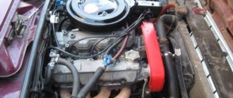
Signs of poor ground contact in KIA Rio 3. We check and fix it ourselves!
During the operation of Kia Rio 3rd and 4th generations, many owners have a very common problem: poor body or engine weight. As a result of high contact resistance, problems may arise with the vehicle's electrical wiring, instability of engine operation, and even problems with starting. There may be several
reasons for a bad “ground” – corrosion of wires or terminals (on the body and battery);
– corrosion of the place where the terminals are attached to the body (rust, paint on bolts and threads);
– break in one of the ground wires.
Broken streamer 918604L200 due to improper installation
Signs of poor body and engine mass
For many, poor body or engine weight begins to manifest itself as strange things when operating your Rio, for example, a suddenly dead battery due to an incomplete charge or an unstable idle. The problem may only appear under certain conditions, such as wet weather or winter. Here are some signs of poor vehicle ground contact:
How to check the quality of the “mass”?
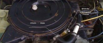
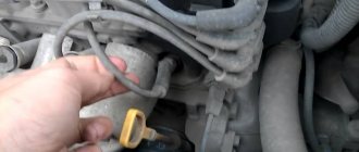
Any check should begin with an external inspection and make sure that the wires are not broken. We check the three main cables: the wire from the battery to the body, the ground wire between the engine and the right “glass”, between the gearbox and the body (located under the engine air filter housing). If there is no external damage, you need to take a multimeter and measure the resistance. We take measurements between the “-” terminal of the battery and the body, engine, in the range of up to 200 Ohms.
Important! Measurements are taken only with the vehicle turned off. Measurements are made only in a de-energized area!
The multimeter readings should be within 1-2 ohms, preferably less. It is important not only resistance at a specific moment, but also that there is good contact at all times, regardless of the weather and time of year. This type of fault must be looked for using more sophisticated equipment, for example, an automotive oscilloscope.
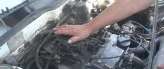
Now we check the connections, the bolts should be well screwed to the body and should not dangle. The fastenings of the terminals to the body must be free of rust, and the terminals themselves must be free of oxides; their condition greatly affects the quality of the contacts.
What to do if the engine “mass” is bad?
If the wires are torn or heavily oxidized, they can simply be replaced; the original wires are quite expensive, so you can choose analogues or buy used braids in good technical condition at a disassembly site, for example, on this site. If the bolts and their mounting holes are rusty, it is enough to replace the terminal mounting bolts and process the threads, removing rust and paint residues from them. With all these procedures, it is necessary to treat all connections and the terminal with a special contact lubricant, which will improve conductivity, reduce resistance and protect against rust.
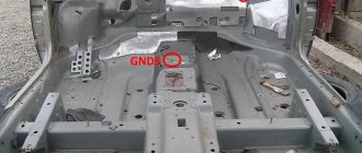
Rusty earth scythe mounting bolts
Numbers of original wires according to the catalog: Hyundai / KIA 918604L000, “-” battery - body Hyundai / KIA 918604L300, gearbox - body Hyundai / KIA 918604L500 (previously 918604L200), engine - body
The article shows only the main ground cables installed in KIA Rio 2011, 2012, 2013, 2014, 2015, 2021, 2017 model years, but do not forget that many other systems and units are connected to the ground with their own individual wires.
Source
Battery weight
The battery negative cable is divided into thin and thick wires. A thick wire runs from the minus charge to the car body. How you tighten the nuts on the battery and engine terminals makes a big difference here. If you loosely secure the contacts, the energy will flow in less volume and the starter will not start. Also, the ECM will not function fully, since the mass comes from the engine. There is also the possibility of malfunctions in other parts of the engine: various sensors, turbines and turbochargers.
It is imperative to make sure that both nuts on the battery negative are sufficiently tightened. First tighten the nut located inside, loosening the outer one, then grab the last one.
The thinner wire is located near the battery and attached to the body. It is the main source of electricity for all parts of the car that need power. It will also not be superfluous to look at how the nuts are tightened to the battery terminal and to the car body itself.
.3.3. Poor Ground Detection
The negative terminal of the battery is connected to “ground” - the metal of the body, engine or gearbox; Moreover, many elements of electrical equipment are connected in such a way that only the positive wire is suitable for them, while the current returns to the battery through the metal of the body. This means that the electrical component mount and the body are part of the electrical circuit. As a result, poor or corroded fasteners can cause the element to fail or cause it to perform erratically or poorly. In particular, light bulbs may glow dimly (especially if the light bulb's ground point is connected to another electrical component that is still on), electric motors may run slowly, and the operation of one circuit may have a seemingly unnoticeable effect on the operation of another circuit.
Don't forget that many vehicles use ground wires between certain components such as the engine/transmission and the body, that is, in areas where there is no direct metal-to-metal contact due to soft rubber mounts or a layer of paint.
To check the reliability of the element's grounding, it is necessary to disconnect the battery and connect one of the ohmmeter probes to a reliably grounded element. Connect another probe to the wire or connection to the body that needs to be checked. The resistance shown by the ohmmeter should be zero; if not, check the connection as follows.
If you suspect there is no ground, disassemble the connection and clean the body area and wire terminal (or the grounding surface of the element) to bare metal. Carefully remove all traces of dirt, then use a knife to remove all paint so that there is reliable contact between the two metal surfaces.
Also interesting: What is the difference between the Niva Urban and the regular Niva?
When assembling, tighten the connector securely; When connecting a wire terminal, install a serrated washer between the terminal and the body surface to ensure a secure connection. When connecting, prevent future corrosion by applying a layer of Vaseline or silicone grease.
Lada 2112 Custom Car › Logbook › ECU weights
I came across an article by McSystem. Actually, here it is below
In January - about Januarys. Again and in detail about the ECM-ECU masses
So, on to the topic! Classic ECM 21124 with ECU January 7.2(+) or M7.9.7 Electrical connection diagram of ECM EURO-2 M7.9.7, January 7.2 LADA 2110 with engine 21124. 21124-1411020-30, 21124-1411020-31.32
Fig. 1 ECM 21124 January 7.2, M7.9.7 Noticed, often described and characteristic problems - unstable idle speed, freezing speed, “jerking” of the engine at start and operation of the cooling fan, unreasonable jumps in the electrical parameters of the ECM during diagnostics. And this is not the entire list. And the whole problem is a rather incorrect wiring of the harness masses, not in relation to the body, but to the ECU. Therefore, in this article you will not see recommendations for tightening the “hoses” of additional mass to the ECU, due to its complete uselessness. This is not a newfangled “razmasovka” or “razminusovka”... Don’t get your hopes up!
The main idea voiced by the authors is that the wiring of the power lines of the ECU and fan and low-current sensor masses is fundamentally incorrect. Rice. 12
Fig.2 Ground connections of the ECM. S6, S7, S8
The sensors must be connected to the ground bus of the ECU board and not have contact with the body! There should be no flow of pulsed and direct currents of the ECU and IM in the sensor mass circuit. And the ECU is securely connected to the body. The rationale is to eliminate the influence of ECU currents (pulse and constant) and fan current on the reliability of sensor readings. Classic approach with data collection and processing systems! But not from AvtoVAZ designers, as usual... Now, in order
Fig. 3 Masses according to AvtoVAZ, or how not to do it
Fig.4 Equivalent circuit in drain
A little theoretical background. Note - the resistance of the ECU connection lines has very real values and consists of the actual resistance of the wire, the transition resistance of the contact in the connector, terminal, etc. And the dimension of these quantities is milliOhms (1000 mOhm = 1 Ohm). In the diagram this is indicated as an equivalent resistor Rm, Rm1, Rm2. For reference: Resistance of 1 m of copper wire with sections 0.35 mm² - 45 mOhm, 0.5 mm² - 35 mOhm, 0.75 mm² - 25 mOhm. Well, there are no “zero resistance wires”! (Whoever managed to buy them, please remain silent)
When the ECU is operating, the current consumption of the ECU itself consists of the consumption currents of the ECU itself and its IM, especially the coils and injectors. Its pulse component reaches 10A, its constant component is about 1.5-2.5A. This current flows through the “mass terminals” of the ECU, “ECU ground” and “sensor ground,” which is fundamentally wrong. Fig.4 At very real resistances Rm, a voltage drop is formed between the connection point to the body and the negative bus (housing) of the ECU - Ucm1. In addition, the flowing current creates a bias voltage drop Ucm2 between the negative bus (housing) of the ECU and the connection point of the sensors. This tension is the root cause of all problems! It is summed with the useful voltage coming from the sensor and enters the measuring unit of the ECU - ADC (Analog-to-Digital Converter). Umeas = Usensor + Ucm2 And then the program processes the already digitized “false” result. With all the ensuing consequences. That is, the problem is not so much the reliability of connecting the ECU to the body, but the incorrect distribution of masses in the harness.
Rice. 5 Masses after modification. The main critical components that have undergone modification are outlined in dotted lines.
Source
How to improve contact reliability
To ensure a good connection of the ground wires to the body, it is necessary to carry out maintenance from time to time. The process is quite simple, the main problem is the location of the fasteners - you have to remove the casing or even interfering parts to get to the right place. This often happens with the mass of the instrument panel. It is recommended to follow simple instructions:
Advice! Instead of a regular nut or bolt, it is better to buy the same stainless steel version. It is not damaged by corrosion, which means it is much more reliable.
If possible, it is necessary to protect the place where the mass is connected from moisture and other adverse influences. It is best to check all available connections at least once a year. It’s enough just to unscrew and check the condition, and if necessary, clean and renew the lubricant so that the metal does not rust.
Weight between engine and body
Line “31”, popularly called “ground”, “minus” or “negative circuit”, is very important for a car. And not only for electrical equipment, but also for many other systems, including the engine or automatic transmission.
Almost all cars have a single-wire on-board network system and the role of the “minus” in this circuit is played by the metal parts of the body. This greatly reduces the number of wires and reduces the cost of the car.
It turns out that all participants in this chain have their own connection to the body - instrument panel, headlights, ECU, engine, etc.
Despite the visual integrity of these connections, over time, due to oxidation and corrosion, the contact slowly and imperceptibly deteriorates, which leads to voltage drops when powerful consumers are turned on or disruption of the system.
I would divide the mass connections into main and local. Let's say that the connection of the head light masses is local and if this connection is disrupted, only the head light will suffer. But if the ground contact from the battery to the body is broken, the entire on-board network will suffer, and this may cause problems in the operation of the engine and other important components and assemblies.
This is how the voltage of the on-board network with problematic masses looks like on the diagnostic graphs
And here is the graph after mass prevention of battery - engine - body
Therefore, a reliable engine-body mass is very important for the proper and trouble-free operation of the entire vehicle.
And the mass of the ECU - engine is even more important, since the voltage in the engine control system does not exceed 5 V. Therefore, this further encourages owners of cars with an engine management system to take the issue of mass more seriously than owners of carburetor cars, where the voltage is 12 -14 B. Because the lower the voltage, the greater the damage from losses in the circuit.
In general, the ground chain must be maintained in perfect condition. It's like an axiom.
Next, let's look at where the engine-body mass is located and how to check it.
Where is the mass of the Chevrolet Niva engine?
But if everything is in order with the relay, and the devices do not work, then there may be a problem elsewhere - the mass attachment point. The negative wire coming out of the battery is connected to the car body and goes to some of the main energy consumers in the form of wires. This is sometimes the difficulty when calling an electrician.
The architecture of the circuit can be described as follows: a wiring harness comes out of the negative terminal, connecting devices operating from one ground point, then wires connecting other ground points are connected to them using a crimp sleeve. As a result, finding a specific mass attachment point is quite difficult.
For example, the mass of the mirror control unit is located behind the trunk trim. But with the engine everything is a little simpler. Since it is connected to the frame and body through pads, which are essentially a dielectric, it has its own wiring harness. The terminals are located on the left side of the engine, below the ignition module. They are responsible for the operation of the ECU and ECM sensors.
Bad ground around the battery
I'll start, perhaps, with the Rechargeable Battery (AB). In modern VAZ cars, a double wire comes off the negative terminal of the battery. Its thick part, about the thickness of a little finger, connects the negative battery and the engine. If the contact of this wire is unreliable, there may be a deterioration in the battery charge, a decrease in the starter rotation speed when starting, as well as problems in the ECM system, because the minus comes from the engine, from the studs on which the ignition distributor hung on carburetor cars. First of all, you should check the tightness of both nuts, between which the wire tip is attached to the engine. First, loosen the outer nut, tighten the nut under the tip, and then tighten the outer one back.
(Fig. Priora battery mass on the body), (Fig. Protection of main power circuits on Priora)
The thin wire connecting the minus battery and the car body is the main connection for all electricity consumers in the car, and in carburetor modifications also for the engine. The tightness of both the M6 bolt directly on the battery terminal and the M8 nut on the body should be checked for poor weight. The location on the body depends on the make of the vehicle.
ECM grounding points
Family 2108-9 and 13-15 1.5L. The ECM weight is taken from the engine, from two M6 bolts securing the plug on the right side of the cylinder head. For carburetor cars, the ignition distributor was attached there. Family of vehicles 2113-15 1.5 and 1.6L with new generation controllers Bosch 7.9.7 or January 7.2, the ECM connection to ground is located on a welded pin securing the metal frame of the central console of the instrument panel to the floor tunnel, through a metal strip with two side lugs on the left and right (Inside the center console, approximately under the ashtray). Unfortunately, as practice has shown, there is no crown washer under the bar, and this is the reason for the poor mass. Because of this, given that the stud itself is painted during the manufacturing process of the vehicle, and is practically not tightened with the corresponding nut, over time, a voltage drift appears in the ADC channels of the DTOZH, TPS and MAF sensors when the radiator electric fan is turned on. As a result, we have a jump in engine speed when the fan is turned on. Treatment methods are described in the FAQ. Thus, in this case, poor electrical contact between the body and the battery negative is also very critical. (See above).
Family 2110-12, 1.5L. The ECM weight is taken from two M6 bolts located on the left side of the cylinder head.
Family 21114, 21124 1.6L, with new generation controllers Bosch 7.9.7 or January 7.2. There is already one M6 bolt in the head. The ground is taken from it only for all four ignition coils, and the ground for the ECM is taken in the cabin, from the welded stud on the ECM mounting bracket, behind the left screen of the center console. In turn, the mass is supplied to the bracket through a pin welded to the engine shield in the middle. The nut on this stud is usually not tightened. If there is insufficient contact in these connections, voltage drift in the ADC channels of the DTOZH, TPS, and MAF sensors is possible when the radiator electric fan is turned on. As a result, we have a jump in engine speed when the fan is turned on. Treatment methods are described in the FAQ. Thus, in this case, poor electrical contact between the body and the battery negative is also very critical. (See above)
Niva family with Bosch MP 7.0 controller. The mass of the ECM is taken from the engine, from the bolts securing the plug, in place of the ignition distributor - distributor, next to the ignition module.
Niva family with Bosch M 7.9.7 controller. The mass of the ECM is taken, as has become typical for the new generation of controllers, from the vehicle body. In this particular case - directly from the studs of its fastening. However, I personally didn’t really like this method due to the fact that the terminal crimped at the end of the wire is much thicker than necessary for the castle washer to be evenly pressed against the car body around the stud. Therefore, I left the washer in place between the body and the controller, but moved the terminal directly under the controller mounting nut.
On Niva 21214, the mass is taken from 2 sides of the block. Next, both wires enter the common harness and go to the ECU connector. In front of the connector there are twists for each brown wire where the mass is distributed for the remaining sensors and the ECU itself.
Chevy Niva family with Bosch MP 7.0 controller. The ECM ground is taken from the engine block, from the M8 studs located in its lower left part, under the ignition module. In the photo above it you can see the mounting studs for the MZ (it has been removed).
Family 2104-07 “classic” with old controllers. The ECM weight is taken from the bolt that tightens the bracket securing the ignition module to the engine block.
VAZ 11183 “Kalina” family. The ECM ground is located on the right side of the engine, on the intake manifold mounting bracket.
Solutions to the problem
If power outages occur frequently or current leakage occurs during long periods of parking, you can improve the system to solve the problem. It’s not difficult to get the job done; the minimum set of tools that every motorist should have is enough. The procedure depends on the nature of the malfunction.
How to make mass better
If removing and cleaning the contacts does not produce any effect, you will have to use more radical repair methods. In some models, the problem with a minus on the body is a real “disease”, so it is necessary to improve the design in order to eliminate the manufacturer’s shortcomings:
It is necessary to monitor the condition of the wires and replace them if there is even the slightest doubt about reliability. It is best to use the same elements as those installed, plus high-quality fasteners.
Installing the mains switch
The switch will protect the car from current leakage, short circuit, and can also serve as an additional anti-theft system. It’s easy to install it yourself; most often, one of two options is used:
The switch is not suitable for cars with an alarm and central locking, since if there is no ground, the system will not work. It is also undesirable to install it on models with a lot of electronics.
It is not difficult to locate the ground wires; they should be periodically removed and processed to ensure good contact. When checking, it is better to use a multimeter, this is the easiest way to detect damage if it is present. It is recommended to replace worn wires in a timely manner, and to prevent leaks, you can install a power switch button.
The ground on the car is missing: what does it mean and how to fix it?
Two wires or one?
To connect the payload to a power source, two wires are required - even a schoolchild knows about this (although Nikola Tesla thought otherwise...).
The most obvious example, quite possibly the one right next to you right now, is a table lamp plugged into an outlet. The few consumers of electricity on the first cars of the late 19th and early 20th centuries were switched on in approximately the same way. The scheme is simple, reliable and quite viable. However, as soon as the production of cars became at least somewhat widespread, the commercial thought of industrialists immediately went in the direction of economy and optimization, and the number of wires in the car was immediately halved - the metal mass of the body began to be used as one of the wires - in common parlance the same “mass” "
The extremely simplified, but quite clear picture above on the right shows a modern car electrical circuit - when the “ground” is the negative wire of the on-board network. However, this was not always the case... Until approximately the 50s of the twentieth century, automakers used both minus and plus as “mass”.
Articles / Practice I see right through you: diagnosing a car using a thermal imager Budget thermal imagers in the form of an attachment to a smartphone have recently moved from the category of startup innovations to the category of everyday gadgets. And one of the interesting areas of their application is repair and maintenance... 9938 7 20 05/28/2018
Standards in the automotive industry had not yet been established, and from an electrical point of view there was absolutely no difference whether to run a plus or a minus on the body. However, by the middle of the century, observations revealed more noticeable corrosion damage to the bodies of those cars in which the “mass” was precisely a plus! It turned out that in this case, electrochemical corrosion develops more intensively, due to the direction of movement of electrons in the electrical circuit - from plus to minus. As a result, the plus “mass” was universally abandoned in favor of the minus one – especially since this did not require the slightest additional investment in production.
Replacing a plus with a minus
Among the models of the domestic automobile industry, the plus on the “mass” was found in Pobeda, in Moskvich 401-402 and earlier, in the first release of the “21st” Volga (since 1960, the electrical equipment system of the GAZ-21 was changed to the traditional one for our days). A car in the USSR was a very durable product, passed down from generation to generation for decades, and after it became known about the harmful influence of the positive “mass”, a fair number of owners of old Muscovites, Pobeda and Volgas began to independently alter the polarity in the electrical system of their cars. Moreover, in the literature for motorists of that time there was a lot of advice and recommendations for such an upgrade.
In principle, the handy car enthusiast coped with the remodeling job in one day. In addition to the banal change of terminals on the battery, it was necessary to change the polarity of the ammeter of the charging indicator on the dashboard and tinker a little with a soldering iron in the radios of models A-8, A-9 and A-12, with a plus on the case. The most difficult thing was reversing the polarity of the generator, but the heater and wiper motors and the starter, which did not have permanent magnets, worked exactly the same when the polarity was changed and did not need any modifications.
In the photo: GAZ-M21 Volga (I) '1956–1958
Today, oddly enough, a reverse evolution is observed! Owners of rare and restored GAZ-21s of the first series and Pobedy, in the struggle for complete authenticity, return the cars to their original configuration of electrical equipment, once changed by the previous owners. Increasing corrosion no longer worries them, since such cars are usually not used “everyday”, 99% of the time they sit with the battery disconnected and go only a few times a year to auto festivals and retro runs.
“Analog” and “digital” – everyone needs “mass”!
Today, many cars use electrical and electronic control via a digital data bus. This gives enormous flexibility in managing numerous electronics, as well as saving on copper - the latter, by the way, is secondary.
In a simple example it looks like this. In a traditional electrical circuit, at least 5 positive wires go through the entire body to numerous taillight bulbs - a brake light, two turn signals, dimensions and reverse (the negative wire, of course, is the body ground). In a digital configuration, there is only one positive wire, and another thin one is the digital bus. Using it, the control unit, located directly next to the rear lights, receives commands and distributes “plus” to those lamps that currently require it.
However, despite this change in the concept of electrical equipment, the role of “mass”, of course, does not disappear - on the contrary, it even increases noticeably! Because digital control units are much more sensitive to deterioration of contact with ground than crude and “stupid” light bulbs and actuator motors, which previously received power via simple “analog” positive wires...
In search of "mass"
“The mass is missing!” - perhaps the most favorite mantra of automotive electricians, mentioned by them both in business and in vain... Hearing this many times, many car owners who remember at least electrical engineering from school physics, think - by the way, why is it almost always the negative “mass” that is lost, and not a plus? After all, it would seem that they are equally necessary for supplying current to the consumer...
The answer here is simple. Due to the fact that the common ground wire, which is the body, is exposed to atmospheric moisture and is prone to corrosion, the electrical elements and modules of the car electronics often lose their minus or receive it through the increased resistance of a rusty and oxidized contact. Contact in positive wires is also sometimes lost, but since they almost do not use rust-prone steel, loss of contact occurs much less frequently than in the case of negative wires...
In principle, the procedure for finding and restoring bad contact at ground connection points is simple and accessible to most car owners who practice independent servicing of their personal cars. Most of the contact points under the hood are not difficult to detect by careful inspection. In the cabin and trunk it is somewhat more complicated - many points of “mass” are hidden under the dashboard and trim. But they are ultimately detectable.
Typically, the electrical ground connection points are threaded rods welded to the body or threaded cage nuts. One way or another, the rusty and oxidized point of the “ground” must be unscrewed with a wrench, the wire tips, the area around the stud, washers and nut must be sanded, to prevent moisture from entering, lubricated with a special aerosol lubricant for electrical contacts (or, in extreme cases, greases such as Litol-24 or graphite) and assembled in reverse order.
It is especially worth noting the importance of the so-called “crown” washers, which are scientifically called “lock washers with external teeth” (they are also sometimes integrated into cable lugs). This small and, at first glance, nonsense that does not deserve attention is extremely important for ensuring high-quality contact at the “mass” points!
The fact is that the body is painted at the factory in a fully assembled form - after painting, nothing is drilled or welded on it. Accordingly, all threaded rods that are points of contact with the “ground,” as well as the areas around them, are coated with paint that does not conduct electric current. Therefore, a special toothed washer is placed under the cable lug placed on the stud - it breaks the paint insulation pointwise and provides a total large contact area without the risk of a rust stain growing around the stud over time. The absence of such washers is unacceptable; replacing them with ordinary flat or groove washers is also unacceptable. Plus you need to know that they are, in a good way, disposable. However, often after body repairs, assemblers forget or ignore these washers...
There are also curious cases - for example, on AvtoVAZ products a few years ago, the owners noted a massive (that's a pun) problem of poor contact at points of mass due to the use of strange castle washers on the factory conveyor, coated with poorly conductive black anodizing...
By the way, you shouldn’t use these washers thoughtlessly and sculpt them everywhere! For example, the positive contact of the starter does not need them at all - two ordinary flat washers and a groover would be much more useful there.
It’s funny, but sometimes in search of “mass” they go to considerable extremes. A separate story is the so-called “minus”. This procedure involves manually making a whole bunch of thick wires with bolt-on terminals at the ends and connecting them to ground and directly to the negative terminal of the battery under the hood of everything that is already connected to them - the engine, starter, gearbox and other things.
In fact, the procedure is completely harmless, harmless and even sometimes useful. Initially, it was used as a method of electrical repair and maintenance in older cars, where it is difficult to diagnose problems with the ground. Therefore, instead of replacing the entire wiring, they simply transferred high-quality backup “mass” wherever possible. As a result, it was possible to eliminate difficult “floating” problems and glitches of electrical equipment with little effort.
However, subsequently, “minus removal” turned from a method of simplified repair into a strange “semi-tuning” event... Wires of incredible thickness are packaged in beautiful decorative insulation “a la snakeskin” and are actually used to decorate the engine compartment. Although with the original promise of improving the stability of the engine and other electronics.
Survey
Have you ever lost weight on your car?
Your voice
Total votes:
Where is the ignition relay located on a Niva Chevrolet?
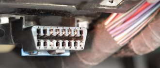
The ignition relay is located in the passenger compartment fuse box; it can be found on the driver's side of the instrument panel, opposite the seat. On the diagram it is usually designated K6 and in the technical description it is sometimes called an addition relay.
Also interesting: Niva-Chevrolet with an Opel engine: brief description, technical characteristics, owner reviews
It is responsible for turning on the fuel pump and supplying voltage to other elements. Triggered when the ignition key is turned. At this moment, you can hear a click behind the instrument panel. This electric coil built into the relay receives voltage and closes the contacts of a certain circuit. If there is no characteristic sound when turning the key, this may indicate its failure.
ADDITIONAL MASS WIRES
If the weight of the engine with the body is bad, then problems arise:
When symptoms of poor engine weight appear, there is a way out of the unpleasant situation - in this case, additional weight on the engine will help. You can install an additional wire in different ways, the most important thing is that it reliably connects the car body with the power unit. For example, one end of the wire can be attached to the stud of the upper shock absorber support, and the other to the stud of the intake manifold of the internal combustion engine. It is important that the wire has a large cross-section, preferably no less than that of the bulk itself.
On new machines, problems with mass wires rarely occur. But on older models, the body studs rust. Finding a lack of ground is not so easy, so car owners use the installation of additional wires. So the additional mass on the generator helps eliminate battery charging leakage.
Bad mass: an inexhaustible source of glitches
Attention! This technique is applicable only to the 2110 and 2113-2115 families of the 'new' model, in which the fan is controlled via a ground wire. In the 2108-2115 family of the 'old' type, the fan can be controlled by +12V switching.
Patient: Car VAZ 21114, manufactured in 2005, mileage 7500 km, 8V, 1.6L.
Complaint: On a warm engine, the TPS position is 1-2%% at idle. A noticeable (100-200 rpm) drift of idle rpm when the electric radiator fan is turned on. Does not depend on the sensor instance (Domestic or GM). The test revealed a change in the voltage at the TPS output from 0.41 to 0.57 V when the electric radiator fan was turned on. Further in the text, in the fork of the measured voltages, the value to the left of the hyphen when the radiator electric fan is turned off, and to the right when it is turned on. Measurements were carried out using a digital tester manufactured by Mastech
Diagnosis: insufficient contact between the ECM ground and the vehicle ground, known as a “bad ground.”
Treatment: An additional thick wire in double insulation, with a cross-section of 3x2.5 sq. mm. additional mass was laid from the negative terminal of the battery to the metal frame of the center console of the instrument panel. The terminals at both ends of the additional wire are crimped and soldered. On the frame, the wire is secured to the ECM ground wire mounting stud, together with its standard ground wires. The terminals on the standard ground wire installed between the battery negative and the car body are also soldered.
The wire is screwed to the intended place. Result: The voltage at the TPS output began to change within 0.39-0.46V. Next, the ground wire going to the radiator fan relay is cut off from the ECM harness and connected to the metal frame with a separate wire. The extension of the wire is made by crimping into a transition tinned copper tube. Result: 0.37-0.39V!!!!!!!! Related measurements: The voltage on the green, ground wire of the TPS before reconnection is 0.056-0.215V. After reconnection 0.03-0.03V! Those. practically does not change! In addition, there is a tendency for the voltage at the TPS output to decrease when the throttle valve is closed as the contact between the ECM and the vehicle ground improves. Conclusion: All the assurances of AVTOVAZ OJSC about improving the quality of electrical connections in manufactured vehicles are not worth a penny. In most cases, it is possible to achieve normal operation of the engine under the control of the ECM I 7.9.7 and January 7.2 only by carrying out additional work to change the electrical circuit of the car and not accepted by the manufacturer as a warranty. PS. Such a thick cross-section of wire was taken because there was no wire with a different cross-section at hand, and it was simply too lazy to cut it into separate wires. In fact, perhaps 2.5 squares would be enough.
Text and photo: I.N. Skrydlov, Lyubertsy (aka Aktuator) ©chiptuner.ru
Causes and symptoms of poor engine grounding
Engine malfunction may be caused by:
Symptoms of a poor motor ground may include:
Often bad grounds are relatively easy to diagnose and correct, usually in a matter of minutes. You can diagnose and repair in your own garage using just a digital multimeter (DMM) and some common tools.
If you don't know where all the engines or transmissions are located in your vehicle, you may want to consult your vehicle's repair manual. You can get a relatively inexpensive copy through Amazon. Haynes manuals come with step-by-step procedures for many maintenance, repair and troubleshooting projects. This way, you will recoup your small investment in a short time.
FINE. So grab your multimeter and let's find those bad grounds in your car.
Corrosion or damage to grounding straps can cause electrical accessories to malfunction.
Electrical ground diagnostics
The following sections are divided between tests. This will make it easier to test the starter and accessory ground paths to identify common electrical system problems.
Here are some important points to keep in mind when troubleshooting your car:
You can use the remote starter switch to crank the engine while testing your vehicle. Connect the switch to the battery and the "s" terminal on the starter solenoid or remote starter relay.
Problems with bulk wires
How do problems with ground contacts manifest themselves?
Engine
If the ground wire from the ECM is oxidized or disconnected, this manifests itself in a spontaneous change in operating modes or the car suddenly stalls. Poor contact from the torpedo causes unstable engine operation at idle.
If the contact is broken, the battery charge deteriorates, the starter speed decreases during startup, problems arise in the ECM, because the second ground wire from the battery goes there. To correct the violation, first check the tension of the nuts securing the thick wire to the engine.
Why is mass needed in a car?
Grounding the engine provides an electrical return path for the starter. Poor engine grounding is a common problem resulting in hard starting and no starting.
The following test takes a voltage drop reading to determine any unwanted resistance in the motor ground circuit.
If the ignition system has a distributor, you can disconnect the high voltage cable from the distributor cap and ground it to the engine (bolt or bracket) using a jumper wire. On other systems, you may be able to remove the fuel pump fuse. Consult your vehicle's owner's manual or vehicle repair manual to locate the fuse. You can also use a remote starter switch. Connect the switch to the starter relay or solenoid (selector relay) control circuit terminals.
You should get a reading of 0.2 volts or less. If necessary, refer to your manufacturer's specifications in your vehicle's repair manual. Did you get a higher reading? There is unwanted resistance in the ground circuit. To find the problem, proceed to the following steps.
Repeat the previous two steps, moving the red wire to the connector connecting the black main ground wire to the battery terminal. When you get a reading around 0.2V or lower, the unwanted resistance is between this and the previous test point. Check for corrosion, broken or loose wires.
Checking grounding in a car
Electronic modules and many electrical components in the engine, transmission and passenger compartment use the body as an electrical ground. This test checks for unwanted resistance at these points, including the secondary ground between the battery and chassis used by some older models. If necessary, consult your vehicle's repair manual.
You should get a voltage drop of 0.2V or less. If the voltage drop is higher, proceed to the next steps.
If you get a reading higher than 0.2 volts, proceed to the next step.
When you get a reading around 0.2V or lower, the unwanted resistance is between this and the previous test point. Check for corrosion, broken or loose wires.
Also, check the voltage drop on the ground circuits that connect the engine to the chassis.
How to check mass with a multimeter
Disconnect the negative terminal of the battery
We take a multimeter and switch it to resistance measurement mode up to 200 Ohms. We check the resistance of the probes themselves by connecting them together
The resistance of the probes themselves is 2.1 Ohms.
Now we connect one probe to the engine. At least here
And the second probe is to the engine control unit, which, in turn, is screwed to the body
What happens - the mass resistance of the engine - the body has practically no resistance? Is everything perfect? Is the engine and body weight OK? What is the problem then? Is the starter defective or are otherworldly forces overcoming you?
The whole thing is much simpler. What is a mass chain in the understanding of an ordinary person? This is just a piece of wire that connects the engine to the body. Just a piece of wire! If we connect ohmmeter probes to the ends of this wire, then we will find out its resistance. It will be minimal - it’s just a piece of copper wire. Right? Right.
If we connect the voltmeter probes to the ends of this wire, we will see zero voltage. After all, where will the potential difference come from on a single piece of wire? Right? Right.
Now let's connect our voltmeter to this ground wire on the car. That is, as when measuring resistance, one probe is to the engine, and the second to the body. They are connected by this piece of wire. Right? Right.
We switch the multimeter to the mode for measuring constant voltage up to 2 Volts. We start the engine and look at the device display.
Oops. And we have tension!
How can this be - we are connected to the ends of one wire, and we have voltage.
So I showed off my artistic creativity and painted a picture of what was happening
Red is the ground wire, and blue is the voltmeter
These values on the multimeter display are nothing more than the voltage drop on our ground wire! Even though it looks great and has minimal resistance, it still drops voltage. Moreover, the greater the consumer current in the circuit, the greater the voltage drop on this wire will be, which can reach several volts!
This is the situation. And the mass of the engine and body is not as good as it seemed at first, and problems from it are inevitable.
How to come out of such a situation as a winner?
First, it is necessary to periodically service this section of the chain.
Unscrew the mass on the body
Do the same with the mass on the engine.
But this doesn't always help. The fact is that this chain still has weak points - crimps.
Crimping lugs, crimping on battery terminal
All this oxidizes over time and cannot fully perform its function.
It is necessary to either re-crimp these connections, or it is better to change these wires sometimes.
Here is a video on the topic of engine mass - body
Well, ideally you can lay additional ground wires: Generator - body
Source
Checking weight in a car
Transmissions on some vehicle models are equipped with a chassis or protective shield for modules, sensors, and solenoids (relays). You can also test these grounds using your digital multimeter.
Clean, repair or replace the transmission ground as necessary. Remove grease, rust and paint from ground terminals or replace damaged ground straps.
General Voltage Drop Values
Choke cables and other equipment can be damaged when high electrical current cannot find the correct path back to ground.
Why is it important to find and correct a bad ground in a car?
A poor engine ground can ultimately prevent the battery from charging properly, receiving signals from the computer correctly, causing the headlights to glow abnormally, causing starting problems and other problems.
Moreover, poor motor grounding can also cause damage. If too much current tries to find the correct ground without success, it will take the easy path through transmission components, transmission cable, throttle cable, wheel bearings, causing severe damage to these and other components.
Whenever you see signs of electrical problems, check the motor ground.
The diagnostic tests described here are simple procedures that you can perform using a digital multimeter. And they'll save you time and money in minutes.
Source