All main modules of the car are driven by one or another control circuit.
They serve not only to transmit power, but also allow you to read information from a large number of sensors, which is subsequently decrypted by the electronic control unit. This allows the engine to operate at its optimum. From time to time, some car components stop working. Most of them are designed to withstand overload, so the protection mechanism - fuses and relays - is triggered. They should be checked first if problems arise with the car.
How is a relay different from a fuse?
Fuses are needed to break the circuit when the current increases above certain values. This is necessary in order to protect wires and electronic components from damage. A sharp increase in current is usually associated with a short circuit.
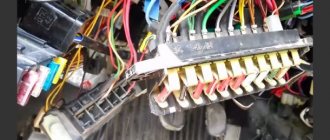
The Chevrolet Niva uses blade-type fuses.
Each of them corresponds to a certain current strength, which is critical for the circuit. When a short circuit occurs, the small jumper inside the fuse burns, thereby breaking the circuit.
That is why it is also called “fusible”. When replacing, you must always de-energize the circuit that it protects, and then install a new element.
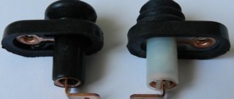
The relay is an electronically controlled switch. Relays are often used to turn on elements remotely, so that there is no need to run a large number of cables to the instrument panel. Typically, a relay uses a lower current to operate than the circuit it controls. Some have a timer function, such as those used to control the windshield wiper or turn signal lamp. This allows you to set an impulse at certain intervals.
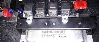
Most relays and fuses are located in the passenger compartment, in a special panel, on the driver's side. But specialized relays that control high-current wires are placed under the hood in the engine compartment.
Ground attachment points in Chevy Niva
Ground mounting points in Chevy Niva from 7.0 1. On the left mudguard near the battery 2. On the left mudguard near the headlight 3. On the right mudguard near the headlight. 4. Logical and power grounding of the ECM - on the cylinder block under the MH (two points) 5. Engine power mass - on the cylinder block, below point 4. 6. In the cabin, behind the fuse box. BUZZ fastening pin (central locking control unit) 7. Trunk, on the left behind the upholstery 8. Trunk, on the right behind the upholstery (here is the mass of the electric pump)
Ground attachment points in Chevy Niva from 7.9.7 1. On the left mudguard near the battery 2. On the left mudguard near the headlight 3. On the right mudguard near the headlight. 4. Absent 5. Engine power mass (with “-” battery) – below MZ 6. In the cabin, behind the fuse box. BUZZ mounting pin (central locking control unit) 7. Trunk, on the left behind the upholstery 8. Trunk, on the right behind the upholstery (here is the mass of the electric pump) 9. On two studs above the controller behind the glove compartment (Controller ground). It is highly advisable to check and tighten it.
AGAIN ABOUT » Ground attachment points » «Controllers January 7.2 and Bosch 7.9.7 have in their 81-pin connector separate pins for sensor ground, which reduces the dependence of sensor readings on each other, increases measurement accuracy and is apparently necessary to comply with European standards 3. However, some smart guy at the wiring harness manufacturing plant, with a light hand, combined all the masses of the sensors with one crimp. Controllers January 5.1, Bosch 1.5.4 actually worked like this, all the masses of the sensors came to one terminal. The difference is small. However, the “naughty” idea of the designers went further. Here is a photo of the electrical wiring of the VAZ 2115. Next to the controller connector there are two wire crimps. The one on the right is a mass of sensors, screens... It would be better if each wire went to its own terminal, but let it remain that way. The crimp on the left (vinyl chloride tubes and electrical tape have already been removed) is the power mass. What is the main mistake of domestic manufacturers? This is the wire that connects these crimps. Marked with yellow dots, the wire itself is just brown. You just need to cut it out, solder the crimps (they took it apart in vain, or what?), and wrap it with electrical tape, that is, restore the insulation. The essence of the modification is that the masses of sensors should come only to the controller. That is, if you remove the connector from the controller, neither the DTOZH, nor the DPS, nor the mass air flow sensor, nor the DD on the body (minus the AB) “ring”. You need to remove the connector from the controller and, for example, the DTOZH, and check the resistance between the engine and the ground wire in the connector. We connect both wires to the engine. Both must have high or infinite resistance - an open circuit. If there is a short circuit, remove the electrical tape next to the controller, look for the specified jumper and remove it. After this, the masses of the sensors will be connected to the machine body only with the controller connector on! All wires have resistance, even very thick ones. Let's remember Ohm's law. The greater the resistance and the greater the current, the greater the voltage. The mass wires obey the same law. Physics, however. When the relay, injectors, IAC are turned on (the ignition keys have a separate thick ground wire and are not involved in our process), the voltage on the ground of the controller itself changes relative to the mass of the car. Apparently the injectors and IAC operate constantly and their intervention is not taken into account. However, current flows through the fan relay and does not flow for a relatively long time. When the fan relay is turned on, the voltage at the ground of the controller is even higher than at the point where the ground wire connects to the body, and if you move along the ground wire, it gradually decreases. There is always a potential difference, it’s just sometimes greater, sometimes smaller. With proper wiring of the ground wires, the voltage on the common wire of the sensors does not change relative to the ground of the controller itself and is practically equal to zero. At the very least, due to the lower sensor currents, the voltage fluctuations are much smaller. A change in voltage on the controller ground relative to the car body or battery negative leads to the same change in voltage on the sensor ground and does not affect their readings. And indeed - on all cars where there is a smell of electronics, for example, on a carburetor eight with electronic ignition, where the Hall sensor is located in the distributor, three wires go to the sensor. Power, signal and ground from a separate terminal of the ignition switch. But let's return to our ram. A jumper added at the factory connects the mass of the sensors to the wire running from the controller to the machine body, on which the voltage changes due to a change in current, in particular, when the fan relay is turned on. As a result of turning on the fan relay, the voltage on the controller ground becomes higher. But, as we remember, it gradually decreases as we move along the wire. The point on the power ground where the ill-fated jumper is connected can be considered “zero”, since the remaining wire between the crimp and the car body is not involved in creating interference. And then everything is simple. The mass of the sensors is connected to “zero”. From this “zero” to the mass of the controller itself, the resistance of the power wire is included. The relay turned on - the voltage on the controller ground became greater than it was. The ADC reference voltage also increased relative to “zero” accordingly. However, the mass of sensors remained in place, at “zero,” and the controller, having processed the ADC readings, will “see” a decrease in the voltage from the sensors. Well, MAF, DTOZh... well, it’s decreased, it doesn’t happen to anyone... Look, what a range! However, for the TPS, reducing the voltage of the closed state will be reduced to storing this very “closed state voltage” in the controller’s RAM, that is, the minimum voltage from the TPS. Here we are. The relay turned off, the voltage on the ground of the controller itself decreased, and the ground voltage of the sensors, together with their readings relative to the ground of the controller itself, increased. The voltage from the TPS increased when the throttle valve was closed, which corresponds to its opening... In short, the speed “stuck”. Moving the fan power wire, additional masses reduce the error voltage, or create a counter-voltage that compensates for the error voltage, but do not eliminate the error itself.” Original article with photo here
Where is the ignition relay located for Niva Chevrolet?
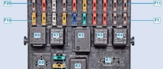
The ignition relay is located in the passenger compartment fuse box; it can be found on the driver's side of the instrument panel, opposite the seat. On the diagram it is usually designated K6 and in the technical description it is sometimes called an addition relay.
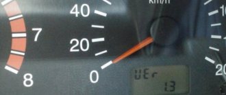
It is responsible for turning on the fuel pump and supplying voltage to other elements. Triggered when the ignition key is turned. At this moment, you can hear a click behind the instrument panel. This electric coil built into the relay receives voltage and closes the contacts of a certain circuit. If there is no characteristic sound when turning the key, this may indicate its failure.
Low beam relay Chevrolet Niva
The low and high beam control units are located on the same board and are marked K4 and K5, respectively. If both low beam lamps do not work, then most likely they can be burned out and the relay should be checked. If you don’t have a spare unit on hand, you can check its performance by swapping K4 and K5. They have the same characteristics and, if necessary, you can use the K5 from the high beam to drive to the nearest auto store and buy a new part.
General information about Niva Chevrolet cars
The restyled modification of the VAZ-21213 was equipped with a VAZ-21213 carburetor engine with a displacement increased to 1690 cm³ and a power of 81.9 hp. at 5100 rpm and maximum torque of 126.1 Nm at 3000 rpm. This internal combustion engine was developed specifically for the Niva VAZ-21213 car. Based on the center-to-center distance of the cylinders of 95 mm, it can be classified as a group of internal combustion engines installed on rear-wheel drive cars. They were located in the engine compartment along the axis of the car. The next modification of the VAZ-21214 (LADA 4×4) was equipped with a VAZ-21214 engine (1.7 l, 82.8 hp, 127.5 Nm) equipped with central fuel injection.
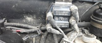
Where is the mass of the Niva Chevrolet engine?
But if everything is in order with the relay, and the devices do not work, then there may be a problem elsewhere - the mass attachment point. The negative wire coming out of the battery is connected to the car body and goes to some of the main energy consumers in the form of wires. This is sometimes the difficulty when calling an electrician.
The architecture of the circuit can be described as follows: a wiring harness comes out of the negative terminal, connecting devices operating from one ground point, then wires connecting other ground points are connected to them using a crimp sleeve. As a result, finding a specific mass attachment point is quite difficult. For example, the mass of the mirror control unit is located behind the trunk trim. But with the engine everything is a little simpler. Since it is connected to the frame and body through pads, which are essentially a dielectric, it has its own wiring harness. The terminals are located on the left side of the engine, below the ignition module. They are responsible for the operation of the ECU and ECM sensors.
.3.3. Poor Ground Detection
The negative terminal of the battery is connected to “ground” - the metal of the body, engine or gearbox;
Moreover, many elements of electrical equipment are connected in such a way that only the positive wire is suitable for them, while the current returns to the battery through the metal of the body. This means that the electrical component mount and the body are part of the electrical circuit. As a result, poor or corroded fasteners can cause the element to fail or cause it to perform erratically or poorly. In particular, light bulbs may glow dimly (especially if the light bulb's ground point is connected to another electrical component that is still on), electric motors may run slowly, and the operation of one circuit may have a seemingly unnoticeable effect on the operation of another circuit.
Don't forget that many vehicles use ground wires between certain components such as the engine/transmission and the body, that is, in areas where there is no direct metal-to-metal contact due to soft rubber mounts or a layer of paint.
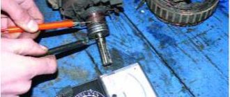
To check the reliability of the element's grounding, it is necessary to disconnect the battery and connect one of the ohmmeter probes to a reliably grounded element. Connect another probe to the wire or connection to the body that needs to be checked. The resistance shown by the ohmmeter should be zero; if not, check the connection as follows.
If you suspect there is no ground, disassemble the connection and clean the body area and wire terminal (or the grounding surface of the element) to bare metal. Carefully remove all traces of dirt, then use a knife to remove all paint so that there is reliable contact between the two metal surfaces.
Also interesting: Oil change. VAZ 21213, 21214 (Niva)
When assembling, tighten the connector securely; When connecting a wire terminal, install a serrated washer between the terminal and the body surface to ensure a secure connection. When connecting, prevent future corrosion by applying a layer of Vaseline or silicone grease.