Ignition module VAZ 2115 - check, malfunctions and replacement
To begin with, I would like to note that the ignition module on the VAZ 2115 is a fundamentally new device that is more reliable than what was installed on earlier models of VAZ cars. The essence of the operation of this device is that it produces a high voltage electric current, which is subsequently transmitted to the spark plugs of the vehicle's ignition system.
Operating principle of the ignition module
As mentioned earlier, the main task of the ignition module is that it generates a high level of voltage, which is subsequently transmitted to the spark plugs. The generated current undergoes a compression procedure, as a result of which a working spark is supplied to one of the spark plugs of the ignition system, and an “idle” spark is supplied to the second. To be more correct in statements, the working spark is supplied to the first and fourth spark plugs of the vehicle’s ignition system, and the “idle” spark is supplied to the second and third. Thanks to this high-voltage electric current supply system, the spark appears at the right stroke and on the right cylinder, which ensures stable operation of the system.
Video. Checking the ignition module of the VAZ 2115
Power to the VAZ 2115 ignition module is supplied directly from the vehicle’s on-board electrical network. The voltage supplied to the ignition module is twelve volts. At the same time, you should know that the negative wire of the ignition module is attached directly to the vehicle body. Design of the VAZ 2115 ignition module
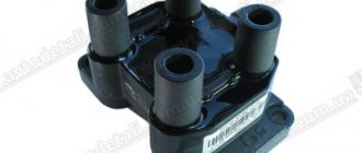
The vehicle ignition module consists of a housing made of plastic, a pair of electronic control units, a pair of high-voltage current transformers, and four outputs for BB-type wires. Dimensions of the VAZ 2115 ignition module: one hundred ten by one hundred seventeen by seventy. The weight of the ignition module is one kilogram, three hundred and twenty grams.
Operating principle of the ignition module
The supply of electric current is carried out using wires of the BB type; the supply of electric current is controlled using a special controller, which makes decisions based on information that comes to it from various sensors of the vehicle. Also, the controller’s tasks include setting the sequence in which the ignition coil operates.
The ignition module can carry out its uninterrupted operation at temperatures from minus forty degrees to plus one hundred and thirty degrees Celsius.
What are the signs that indicate a faulty ignition module?
There are several typical signs that directly indicate problems with the ignition module:
1. The engine idle is floating. 2. Engine thrust periodically disappears for no reason. 3. The car picks up engine speed very slowly when accelerating. 4. The cylinders stop working in pairs.
Note that the same signs indicate a malfunction of the BB wires and spark plugs of the vehicle’s ignition system, so in the beginning, you should check them, and if everything is fine with them, then replace the ignition module.
Tools you will need:
To replace the ignition module on a VAZ 2115 car, you will need very few tools:
1. Open-end wrenches for seventeen and thirteen. 2. Ten socket wrench. 3. Hexagon.
Replacing the ignition module on a VAZ 2115 with your own hands
To independently replace the ignition module on a VAZ 2115, you should strictly adhere to a certain sequence of actions, which you can find below:
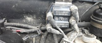
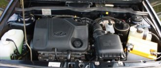
1. First, you must find the ignition module itself in the engine compartment. This can be done by following the high-voltage wires that come from the spark plugs of the ignition system.
2. Next, you must disconnect the negative cable from the battery.
3. Now, you need to remove the block to which the wires are connected from the ignition module.
4. Next, you should disconnect the high-voltage wires.
5. Now, you can unscrew the mounting bolts that secure the ignition module to the engine and remove it.
6. Then all you have to do is mount the new ignition module and assemble the entire structure in reverse order.
How to replace the ignition module on a VAZ 2113-VAZ 2115?
Removal: 1) First disconnect the “-” terminal from the battery, thereby de-energizing it. (How to remove the minus terminal in order to de-energize the battery, see the article: “Replacing the battery”).
2) Then find the location of the ignition module in the engine, and after finding it, disconnect the four high-voltage wires that are connected to it.
3) Next, disconnect the wire block by squeezing the retaining clip that secures it to the module.
4) Next, remove the three nuts that secure this module to the bracket.
Note! To make it easier for you to visually determine, look at the photo below, which shows the places where three nuts secure the module to the bracket!
5) Then remove the module from the three long pins that are present on the bracket.
Installation: The ignition module is installed in the reverse order of removal, but when installing it back, you must know two things:
1. After the ignition module is installed, look at its surface, you see the numbers shown there: 1, 2, 3, 4. So, these numbers indicate the numbers of the corresponding cylinders.
2. Have you noticed that the same numbers are present at the tips of the high-voltage wires: 1, 2, 3, 4. All this was done to make it easier for you to determine which of the high-voltage wires should be connected to the module where.
Note! When reinstalling the module, connect all high-voltage wires strictly by numbers, for example: “the first wire - to the first terminal”, “the second wire - to the second terminal”, etc.
Checking the ignition module for functionality:
To check the module, you will need a “high-voltage arrester”, which can be purchased at a car store for a price in the region of 900-1500 rubles. Using this spark gap, you can check for serviceability: the ignition module, the ignition coil, and the high-voltage wires themselves for the presence of sparking.
Note! The video clearly shows that the ignition module is working properly, because when all the wires are connected to it one by one, a spark constantly appears on the spark gap, but the last check shows that the spark breaks off a little, but still the module performs well and does not need to be replaced !
Important! When working with the ignition module, be careful, and under no circumstances carry out any actions with it without de-energizing the battery!
Ignition module diagram 2115
The circuit diagram and connection diagram of this electronic device is presented below.
The ignition module installed on the Lada Samara is extremely resistant to both low and high temperatures. Operating temperature range: -400/+1300C.
The only negative point in the operation of this electronic device is its complete inability to repair. However, even a novice car enthusiast can replace it on his own.
Experts consider the most common malfunctions of the Samara ignition module to be:
Unstable operation of the power plant when accelerating the vehicle.
Decrease in engine power.
“Intermittent” idle speed.
Malfunction of paired (1/4 – 2/3) engine cylinders.
Attention! The detection of the above malfunctions is not final evidence of failure of the ignition module, since similar symptoms are possible due to malfunctions of the spark plugs and unreliable connection of high-voltage wires.
Instructions for repairing and replacing the ignition coil
Replacing short circuits on valves 8 and 16 in an engine represents a sequence of steps:
- The module can be easily found by the high voltage wires coming from the SZ spark plugs.
- Before starting work, you must turn off the negative voltage on the battery.
- The next step is to disconnect the wire block from the short circuit and high-voltage wires.
- Next, you need to unscrew the bolts securing the MZ to the engine, and you can dismantle the device.
- Now you need to install a new or repaired device and perform the steps in reverse order.
When connecting, follow the connection diagram in the manual.
It is located in the engine compartment. The easiest way to detect it is to find the BB wires. One end goes to the spark plugs, the other to the module.
You need to connect strictly in a certain order: Wires 1 and 4 of cylinders go to one winding, 2 and 3 to the other. The numbering is indicated on the MH. Pay attention to the picture.
If you hold the module strictly in front of you, you need to connect it as follows:
- 1st cylinder - lower left explosive outlet;
- 2nd - top left;
- 3rd - upper right;
- 4th - bottom right.
Checking the Lada Samara ignition module
The correct functioning of the ignition module not only has a significant impact on the start of the vehicle’s power plant, but also ensures the stability of its operation in all modes. To carry out a complete diagnosis of this electronic device, you need quite complex equipment, available only in large specialized workshops. However, you can check the functionality of the ignition module yourself in an amateur garage. The only logistical support for this test will be a multimeter, or tester.
The first and simplest way to determine the functionality of the ignition module is to replace it with a known-good device.
Attention! When using a donor car for testing, do not forget that only the first Lada Samara models were equipped with the ignition module, as a separate device. Machines of later releases are equipped with separate type devices (the switch is included in the electronic control unit).
The procedure for replacing the ignition module includes the following steps:
Preparation of the necessary tools: wrench 17 (open-end), wrench 13 (open-end), wrench 10 (socket), hexagon.
De-energizing the vehicle by disconnecting the “-” terminal from the battery.
Removing the wire block.
Disconnecting high voltage wires.
Unscrewing the fastenings to the power unit.
Recess of the ignition module (unscrews from the holder using a hexagon).
Installing a replacement module involves connecting high-voltage wires (the module body contains hints). In addition, the wire terminals also have corresponding designations. We install the ignition module, performing the manipulations in the reverse order, followed by checking its functionality.
Another method involves measuring the resistance of individual module elements using a multimeter (tester). Using the tester probes, we close the “paired” terminals of the module, which provide connection to high voltage wires, and measure the resistance value.
The resistance value of a working device should be approximately 5.4 kOhm. The discrepancy between this parameter and the specified value indicates that the VAZ 2115 ignition module is inoperative.
There is another, so-called “folk” method, or the “shake-up” method. With the power plant running, lightly tap the module. Despite all the “technical non-scientific” nature of such manipulations, they are capable of producing results. True, only in the case when the contact of the elements inside the housing is broken.
CHANGING THE IGNITION SYSTEM MODULE
When repairing the ignition module does not produce positive results, all that remains is to look for and install a new device. Most mechanics recommend choosing a “GM” device as a very reliable product. Its cost varies in different regions, but is close to 2000 rubles. Replacing the ignition module can be done independently, there are no special features, and no special devices are needed. For work, prepare:
- Ignition unit for replacement;
- Key to "13";
- Rags.
The work can easily be done in a garage or on level ground. Work order:
- Open the engine compartment hood and disconnect the battery terminals. It is quite enough to remove the terminal only from the negative side.
- After this, we remove the high-voltage wires from their installation locations. You need to remember where which wire was located. If you doubt your abilities, then make marks. Wires cannot be swapped. A new spare part can be damaged.
- At the next stage, carefully disconnect the connector with wires from the module. Use the key set to “13”, which unscrews the three nuts securing the device to the motor.
- When the nuts are removed, the device is removed from the engine.
Now they use rags to wipe the installation area and around it. Carefully inspect the new device and begin installing it. It is carried out in the reverse order to removal
Once again I would like to remind you of the importance of installing high-voltage wires in their places. If difficulties still arise, then take another look at the block
It shows the numbers of high-voltage wires.
We check the ignition module on the 8-valve VAZ-2114 with our own hands: signs of malfunction
When independently diagnosing an engine, its systems and characteristics, a minimum of equipment is used. For example, before checking the ignition module of an 8-valve VAZ-2114 car, it is advisable to have a special stand, the necessary software, or, in extreme cases, an oscilloscope. None of us have or will have such equipment, so for preliminary testing we will use available tools and devices.
How to check the ignition module of a VAZ-2114
Interruptions and jerking when driving, a shaking engine, difficult starting or even engine failure are the main signs of failure of the ignition module.
The difficulty of diagnosing on your own is that the module combines several devices at once , and it itself is made in a single housing, and there is no way to check each device separately. At least with your bare hands. Nevertheless, something can be done in order to, if not repair, then at least know for sure the cause of the malfunction.
Checking the quality of contacts
First of all, without dismantling anything, it is worth checking the quality of contact on all blocks of the low voltage circuit , as well as establishing the presence of contact on the high voltage wires.
Checking the presence of power on the ignition module
Checking the voltage on the ignition module pads
In order to know that it is the module that is faulty, let’s check whether power is supplied to it. To do this, we find the connector in the block, and there we look for a contact marked with the letter A. To control the power supply to the module, take a multimeter, set it to measure alternating current up to 20 V , install one probe (negative) to engine ground and turn on the ignition. We install the second probe on terminal A on the block. If the electrical equipment is in good working order, the multimeter will show 12 V, which means that power is supplied to the module, we look further for the cause of the malfunction.
Ignition switch and features of its replacement
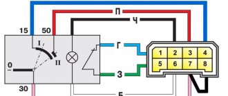
ZZ plays an important role in the vehicle's SZ, both for an 8-cl and 16-cl engine. It is activated when the starter is working, thanks to it the lighting, turn signals, and power windows work.
Scheme ZZ VAZ 2115
Replacement or repair of the VAZ 2115 ignition switch may be required if:
- lost or broken keys;
- the lock was damaged during an attempted theft;
- the 3Z cylinder is faulty;
- The contact group does not work.
Ignition switch VAZ 2115
To replace you will need: a set of keys, a hammer, screwdrivers, a thin chisel.
The replacement procedure consists of the following steps:
- The car's power is turned off by disconnecting the negative terminal from the battery.
- We remove the steering wheel.
- Next you need to remove the steering column switches.
- Then you need to loosen the bolts securing the clamp that holds the ZZ on the steering column. If the heads are cut off, the bolts should be carefully knocked out using a hammer and a thin chisel.
- Now you need to disconnect the wiring harness.
- Next, you need to completely unscrew the bolts from the 3Z housing and you can remove it.
- A new device is installed in place of the old one.
- Assembly is carried out in reverse order.
After assembly, you should start the engine and check the operation of the switch (the author of the video is the MY LADA channel).
Checking the connector contacts
We have already carried out a preliminary check and made sure that power is supplied to the ignition module. Now it’s worth dealing with the contacts separately. With the ignition on, you need to connect a test lamp to contact A and contact B.
The control can be a regular low-power 12-volt lamp with soldered wires, or you can use a car test probe with a 12-volt voltage indicator.
Checking the ignition module
To check the functionality of the module, we attach the contacts from the test lamp or probe to terminals A and B , then crank the engine with the starter.
If the lamp begins to blink, the module produces a voltage break similar to a contact breaker.
In this case, everything is in order with contacts A and B.
If the lamp does not respond to the starter, the module is definitely faulty.
We check module 2114 using available methods
The most effective way to find out that the ignition module is not working is to take a device that is known to work and try to start the engine on it . It is clear that not every module from the second generation eights, nines and Samars may be suitable.
Depending on the type of ignition system, Samara may have a coil installed instead of a module, but we need exactly the module from the 8-valve injection 2114. Everything is simple here - the engine is running, which means the module has become obsolete, we replace it with a new one. However, there is a high probability that the high-voltage wires are broken and this will ruin not only the entire diagnostic picture, but also someone else’s ignition module.
Checking the integrity of high-voltage wires
Therefore, before checking the module itself, you need to make sure that the high-voltage wires are in order, do not break through to ground and allow current to pass through.
The action algorithm for subsequent verification is as follows:
- Checking the ignition module on the high-voltage circuit for an open circuit . To do this, you will need a multimeter that is set to resistance measurement mode. In the module, the ignition coils are connected in parallel - the first and fourth, second and third. To check, take the multimeter probes and install them (with the ignition off) into the connectors for high-voltage wires on the module. First 2 and 3, then 1 and 4 cylinders. The resistance between parallel coils should be 5.1-5.5 ohms. If the resistance is infinite, there is a break in the network and the module must be replaced.
Checking the ignition module for a break
Video about checking the ignition module on a VAZ-2114
How to set the ignition yourself?
Precise ignition adjustment on the VAZ 2115 injector is performed using a special strobe light. If this is not possible, you can set the ignition on the VAZ by spark.
To do this, follow these steps:
- First of all, the engine is warmed up until it reaches operating temperature.
- The distributor does not need to be removed, but only relaxed.
- You need to remove the central wire from the distributor.
- The piston in the 1st cylinder must be at TDC (the marks are set differently on 8 and 16 valve engines).
- Now you need to hold the short-circuit wire with your left hand and turn on the ignition.
- Use your right hand to adjust the distributor counterclockwise, while keeping the high-voltage wires above the metal.
- Then similar actions are performed, turning the distributor clockwise until a spark appears.
- At this point, the alignment ends, and the distributor is fixed in its regular place.
With the ignition set correctly, the car will operate without interruption with optimal fuel consumption and maximum power.
We check the ignition module on the 8-valve VAZ-2114 with our own hands: signs of malfunction
When independently diagnosing an engine, its systems and characteristics, a minimum of equipment is used. For example, before checking the ignition module of an 8-valve VAZ-2114 car, it is advisable to have a special stand, the necessary software, or, in extreme cases, an oscilloscope. None of us have or will have such equipment, so for preliminary testing we will use available tools and devices.
How to check the ignition module of a VAZ-2114
Interruptions and jerking when driving, a shaking engine, difficult starting or even engine failure are the main signs of failure of the ignition module.
The difficulty of diagnosing on your own is that the module combines several devices at once , and it itself is made in a single housing, and there is no way to check each device separately. At least with your bare hands. Nevertheless, something can be done in order to, if not repair, then at least know for sure the cause of the malfunction.
Checking the quality of contacts
First of all, without dismantling anything, it is worth checking the quality of contact on all blocks of the low voltage circuit , as well as establishing the presence of contact on the high voltage wires.
Checking the presence of power on the ignition module
Checking the voltage on the ignition module pads
In order to know that it is the module that is faulty, let’s check whether power is supplied to it. To do this, we find the connector in the block, and there we look for a contact marked with the letter A. To control the power supply to the module, take a multimeter, set it to measure alternating current up to 20 V , install one probe (negative) to engine ground and turn on the ignition. We install the second probe on terminal A on the block. If the electrical equipment is in good working order, the multimeter will show 12 V, which means that power is supplied to the module, we look further for the cause of the malfunction.
HOW TO CHECK THE SYSTEM FOR OPERATION
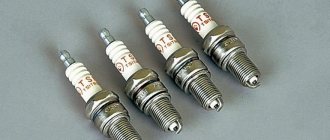
In any case, the check begins with the candles. To do this, they need to be removed from their nests. This is also easy to do. Remove the tips of the high-voltage wires from them and, using a wrench for turning out the spark plugs, remove them from their places.
Next comes their inspection, cleaning and testing. They should have a working brown color, with no soot or soot. If their presence is observed, then there may be wear on the pistons and rings. In any case, the spark plugs are cleaned, checked and, if necessary, the gap between the electrodes is adjusted. After this you can check their functionality
There are special probes for these purposes. “Craftsmen” manage to make such products themselves from a piezo lighter. If nothing like this is available, then check it on the engine. It’s good if there is a car nearby with a known good starting system. This will make it possible to make an accurate diagnosis for candles. If they are in good condition, the search continues further.
Checking for the presence of high voltage is dangerous due to a possible sensitive electric shock, so we will touch on other methods. Let's talk about how you can determine ignition coil malfunctions and check this system:
- The simplest method is to replace the unit with a working device. It is not always possible, since not all drivers carry this device with them in reserve;
- They also advise, which has been tested many times, to move the device or knock on it while the motor is running. If changes are noticeable, they indicate poor contact inside the device. Sometimes it's fixable;
- Check with a tester or multimeter in resistance measurement mode. The resistance of the paired terminals of the coils, 1 and 4, as well as 2 and 3, is measured. It should be identical for both windings and equal to approximately 5.4 kOhm.
Checking the connector contacts
We have already carried out a preliminary check and made sure that power is supplied to the ignition module. Now it’s worth dealing with the contacts separately. With the ignition on, you need to connect a test lamp to contact A and contact B.
The control can be a regular low-power 12-volt lamp with soldered wires, or you can use a car test probe with a 12-volt voltage indicator.
Checking the ignition module
To check the functionality of the module, we attach the contacts from the test lamp or probe to terminals A and B , then crank the engine with the starter.
If the lamp begins to blink, the module produces a voltage break similar to a contact breaker.
In this case, everything is in order with contacts A and B.
If the lamp does not respond to the starter, the module is definitely faulty.
We check module 2114 using available methods
The most effective way to find out that the ignition module is not working is to take a device that is known to work and try to start the engine on it . It is clear that not every module from the second generation eights, nines and Samars may be suitable.
Depending on the type of ignition system, Samara may have a coil installed instead of a module, but we need exactly the module from the 8-valve injection 2114. Everything is simple here - the engine is running, which means the module has become obsolete, we replace it with a new one. However, there is a high probability that the high-voltage wires are broken and this will ruin not only the entire diagnostic picture, but also someone else’s ignition module.
Checking the integrity of high-voltage wires
Therefore, before checking the module itself, you need to make sure that the high-voltage wires are in order, do not break through to ground and allow current to pass through.
The action algorithm for subsequent verification is as follows:
- Checking the ignition module on the high-voltage circuit for an open circuit . To do this, you will need a multimeter that is set to resistance measurement mode. In the module, the ignition coils are connected in parallel - the first and fourth, second and third. To check, take the multimeter probes and install them (with the ignition off) into the connectors for high-voltage wires on the module. First 2 and 3, then 1 and 4 cylinders. The resistance between parallel coils should be 5.1-5.5 ohms. If the resistance is infinite, there is a break in the network and the module must be replaced.
Checking the ignition module for a break
Video about checking the ignition module on a VAZ-2114
MODULE DEVICE
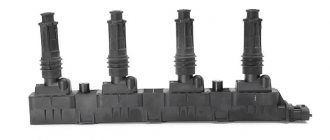
The device includes two coils, the main task of which is to generate high voltage. A two-channel electronic switch helps them in this. All these parts are contained in a housing made of durable plastic. The housing has a low-voltage connector for connecting the supply voltage and supplying control pulses. There are also leads for connecting high-voltage wires that are connected to the spark plugs.
Electrical diagram of the VAZ 2114 starting system
The figure shows an electrical diagram of the VAZ 2114 starting system. As can be seen from the figure, it consists of:
- Battery;
- Ignition switch;
- Relay that turns on the ignition;
- Hall Sensor;
- Semiconductor signal receiver from the sensor;
- Electronic switch;
- Ignition module.
- High voltage terminals.
The electrical diagram also shows the fuses of the power supply circuits of the electronic units. Let's try to look at the device and operating principle of the ignition coil. As already noted, there are two of them in the block; they are identical in design. The ignition coil circuits of one and the other are also absolutely identical. The principle of operation of the ignition coil remains the same. Both consist of cores made of electrical steel. Two windings are wound on them. One of them is low-voltage, and the second produces high-voltage voltage to ignite the working mixture.
The ignition coil connection circuit is made in such a way that one end of the low-voltage winding is connected to the supply voltage, and the other end of these windings is connected to a transistor generator. Each coil has its own transistor. The high-voltage leads are connected directly to the spark plugs; each winding supplies energy to two spark plugs. One of them outputs pulses to cylinders 1 and 4, and the second to cylinders 2 and 3.
The wires on the ignition module are arranged as follows. Contacts A and B receive control pulses from the electronic switch, pin D receives power from the machine’s on-board network. The terminal marked with the letter C is connected to the vehicle ground.
