ECONOSTAT
Repair and cleaning of the VAZ 2109 carburetor
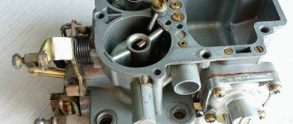
The econostat enriches the combustible mixture prepared by the second chamber at maximum throttle opening. It is made in the form of a separate sprayer, which is an inclined tube located in the upper part of the second mixing chamber. The outlet of the atomizer is located near the center of the chamber above the hole of the small diffuser. Fuel is supplied to the econostat sprayer directly from the float chamber through a tube, at the lower end of which there is a fuel nozzle. The tube is installed vertically in the carburetor cover and reaches almost to the bottom of the float chamber. The econostat channels are entirely located in the carburetor cover. Since the econostat atomizer is located in a low vacuum zone, the flow of fuel from it and, accordingly, the necessary enrichment of the combustible mixture begins only at a high crankshaft speed and with the throttle valves fully open, when the vacuum above the diffuser of the second chamber becomes sufficient to extract fuel from the float chamber.
ACCELERATING PUMP
Diaphragm type accelerator pump with two nozzles directed into both mixing chambers. The accelerator pump housing is combined with the carburetor body and is closed by a cover with a hole for a telescopic spring-loaded diaphragm pusher. The accelerator pump is driven by a cam mounted on the throttle valve axis of the first chamber. When you press the gas pedal, the cam, rotating together with the throttle valve axis, acts on the profiled end of the pump drive lever. The other end of the lever presses the diaphragm pusher. The pump sprayer is made in the form of two thin tubes with calibration holes at the ends, connected together by a common body. It is installed at the end of the vertical channel of the carburetor body. The connection is sealed with a rubber ring placed on the spray body. The nozzle is kept from moving by the carburetor cover. A ball discharge valve is installed in the spray body. The check (suction) valve is pressed into the lower part of the vertical channel. Fuel enters this channel through a hole in the side wall of the float chamber. The ends of the accelerator pump nozzle tubes are directed into the spaces between the walls of the small and large diffusers of both chambers. In this case, the outlet openings of the atomizer tubes are oriented so that the fuel stream from them does not fall on the walls of the mixing chambers, small diffusers and throttle valve axles, that is, the fuel is injected directly into the intake pipe. The performance of the accelerator pump is determined by the cam profile of its drive. The cam has markings stamped on its surface. The characteristics of the accelerator pump also depend on the diaphragm pusher spring and the flow sections of the spray tubes. The stiffness of the spring determines the fuel pressure in the nozzle, and the diameter of the outlet holes of the nozzle determines the duration of injection. The sprayer is also marked.
A distinctive feature of the accelerator pump of the Solex family of carburetors is the absence of a drain jet or other devices that reduce the amount of fuel injected when the throttle valve is slowly opened. All gasoline displaced by the diaphragm from the cavity of the accelerator pump enters through the atomizer into the mixing chambers. Therefore, there is another feature of Solex carburetors in the basic version, which is directly related to the operation of the accelerator pump. When accelerating a car with partial pressing of the gas pedal, the flap of the second chamber is not yet open, and gasoline is injected into this chamber. To prevent it from accumulating there, there must be a gap between the chamber wall and the closed throttle valve, visible to the light.
Acceleration pump: 1 - outlet of the sprayer in the second chamber; 2 - outlet of the sprayer in the first chamber; 3 - sprayer; 4 — discharge valve ball; 5 - diaphragm; 6 — diaphragm return spring; 7 — pusher spring; 8 — pusher; 9 — lever; 10 — lever axis; 11 - cam; 12 — axis of the throttle valve of the first chamber; 13 — suction valve ball; 14 — channel for supplying fuel from the float chamber.
Carburetor SOLEX 21083 diagram and device
Diagram of carburetors 2108, 21081, 21083 Solex installed on the engine of front-wheel drive VAZ 2108, 21081, 21083, 2109, 21091, 21093, 21099. All these carburetors are based on the same design. The only difference is in the parameters (jet sizes, etc.). Modifications of Solex carburetors installed on Niva, Oka and some rear-wheel drive VAZ car models have some features in the device (for example, the absence of a “return”, a different UN atomizer, etc.).
1
.
Carburetor heating unit 2
.
Throttle valve of the first chamber 3
.
Pipe for suction of crankcase gases 4
.
Accelerator pump drive lever 5
.
Accelerator pump drive cam 6
.
Accelerator pump diaphragm 7
.
Fuel jet for power mode economizer 8
.
Pump housing 9
.
Power mode economizer diaphragm 10
.
Shut-off solenoid valve 11
.
Idle fuel jet 12
.
Carburetor cover 13
.
Main air jet of the first chamber 14
.
Air damper 15
.
Accelerator pump nozzles with fuel supply valve 16
.
Trigger diaphragm 17
.
Starter adjusting screw 18
.
Idle mixture quantity adjusting screw 19
.
Second chamber locking lever 20
.
Pipe for supplying vacuum to the vacuum regulator of the ignition distributor 21
.
Idle mixture quality adjusting screw 22
.
Throttle valve control sector 23
.
Throttle valve drive lever 24
.
Adjusting screw when opening the throttle valve of the first chamber 25
.
Air damper control lever 26
.
Starter rod 27
.
Electrical wire of the limit switch of the forced idle economizer 28
.
Choke lever 29
.
Main air jet of the second chamber 30
.
Emulsion tube 31
.
Sprayer of the main dosing system of the second chamber 32
.
Fuel supply pipe 33
.
Fuel drain pipe into tank 34
.
Fuel filter 35
.
Needle valve 36
.
Throttle valve of the second chamber 37
.
Throttle lever of the second chamber 38
.
Main fuel jet of the second chamber 39
.
Throttle valve drive lever of the second chamber 40
. Float.
|.
The first chamber of the carburetor. ||. Second chamber of the carburetor. 1
.
Accelerator pump drive lever. 2
.
Trigger diaphragm adjustment screw. 3
.
Trigger diaphragm. 4
.
Air duct of the starting device. 5
.
Solenoid shut-off valve. 6
.
Fuel jet for idle system. 7
.
Main air jet of the first chamber. 8
.
Air jet of the idle system. 9
.
Air damper. 10
.
Sprayer of the main dosing system of the first chamber. eleven
.
Accelerator pump spray pipes. 12
.
Sprayer of the main dosing system of the second chamber. 13
.
Econostat sprayer. 14
.
Main air jet of the second chamber. 15
.
Air jet of the second chamber transition system. 16
.
Balancing channel of the float chamber. 17
.
Float chamber. 18
.
Fuel needle valve. 19
.
Fuel return fitting. 20
.
Mesh filter. 21
.
Fuel supply fitting. 22
.
Power mode economizer diaphragm. 23
.
Fuel jet for power mode economizer. 24
.
Ball valve for power mode economizer. 25
.
Float. 26
.
Econostat fuel jet with tube. 27
.
Fuel nozzle of the second chamber transition system. 28
.
Emulsion tube of the second chamber. 29
.
Main fuel jet of the second chamber. thirty
.
The outlet of the transition system of the second chamber. 31, 33
.
Throttle valves. 32
.
Damping jet. 34
.
Slot of the transition system of the first chamber. 35
.
Idle air system outlet. 36
.
Heating block. 37
.
Adjusting screw for the “quality” of the fuel mixture. 38
.
Crankcase ventilation system fitting. 39
.
Vacuum tap connection to the vacuum ignition timing regulator. 40
.
Main fuel jet of the first chamber. 41
.
Emulsion tube of the first chamber. 42
.
Accelerator pump ball valve. 43
.
Accelerator pump diaphragm. 44
. Accelerator pump pusher.
How does Solex differ from Ozone and Weber?
The main difference between Solex carburetors and devices of previous families is the possibility of installing it on transversely located power units with the float chamber forward. This installation option made it possible to eliminate the leanness of the fuel mixture when the car enters a turn, climbs, or during sudden acceleration. In addition, Solex has a completely different float chamber design. It has a two-section design, which allows the device to be used both on front-wheel drive cars and on classic cars.
Modifications and applicability of Solex carburetors
| Modification | Applicability | Engine volume, cm3 | Notes |
| DAAZ-2108–1107010 | VAZ 2108, 2109 | 1,3 | |
| DAAZ-21081–1107010 | VAZ 21081, 21091, ZAZ 1102 | 1,1 | |
| DAAZ-21083–1107010 | VAZ 21083, 21093, 21099 | 1,5 | |
| DAAZ-21083–1107010–31 | VAZ 2108, 2109, 2110, 2111 | 1,5 | Has a semi-automatic starting device |
| DAAZ-21083–1107010–35 | VAZ 2108, 2109, 2110, 2111 | 1,5 | Has a two-level semi-automatic starting device (winter/summer) |
| DAAZ-21083–1107010–62 | VAZ 2109, 2115 | 1,5 | Has an electronic device for controlling the composition of the combustible mixture |
| DAAZ-21083–1107010–05 | VAZ 2109 | 1,5 | |
| DAAZ-21412–1107010, DAAZ-21412–1107010–30 | AZLK 2141, 2141–23 | 1,5/1,8 | |
| DAAZ-1111–1107010 | VAZ 1111, 11113 "Oka" | 0,65/0,75 | |
| DAAZ-21051–1107010 | VAZ 2103, 2105 | 1,5 | |
| DAAZ-21053–1107010 | VAZ 21074, 21061 | 1,6 | |
| DAAZ-21051–1107010–30 | VAZ 2104, 2105 | 1,3 | |
| DAAZ-21053–1107010–62 | VAZ 2107, 21072, 21074 | 1,3/1,5/1,6 | |
| DAAZ-21073–1107010 | VAZ 2121, 21213 "Niva" | 1,6/1,7 |
What is the difference between carburetor 21081 and 21083
If you compare the two main modifications of Solex carburetors (21081 and 21083), used on front-wheel drive Sputniks and Samaras, then visually you will not find any differences between them. The difference exists only in the operating parameters of some of their elements.
Table: comparison of basic calibration data for Solex 21081 and 21083 carburetors
| 21081 | 21083 | |||
| For 1st camera | For 2nd camera | For 1st camera | For 2nd camera | |
| Mixing chamber diameter, mm | 32 | 32 | ||
| Diffuser diameter, mm | 21 | 23 | 21 | 23 |
| Air jet of the main dosing system | 165 | 135 | 155 | 125 |
| Fuel jet of the main metering system | 95 | 97,5 | 95 | 97,5 |
| Idle air jet | 170 | 170 | ||
| Idle fuel jet | 39–44 | 39–44 | ||
| Air jet of the second chamber transition system | 120 | 120 | ||
| Fuel nozzle of the second chamber transition system | 50 | 50 | ||
| Economizer fuel jet | 40 | 40 | ||
| Accelerator pump cam number (size) | 4 | 7 | ||
| Throttle valve starting gap, mm | 1,0 | 1,1 | ||
| Air damper starting gap, mm | 2,7±0,2 | 2,5±0,2 | ||
| Needle valve hole diameter, mm | 1,8 | 1,8 | ||
| Vacuum regulator hole diameter, mm | 1,2 | 1,2 | ||
Carburetor VAZ 2109 Solex - Setup video
© 2016-2021 24techno-guide.ru
All rights reserved.
Use of site materials is possible only if you install an active direct link to our resource. FEEDBACK
Home
(Main page of the site)
Auto
(Reviews, reviews, test drives of cars)
Engines
(Description and design of various engines)
Techno
(Articles about equipment and mechanics)
Tuning
(Review of tuned cars)
Repair
(Do-it-yourself repairs)
Tractors
(Tractor special equipment)
Osago
(All about car insurance)
Car audio
(Music for the car)
Car LAWS
(Traffic rules, fines and car laws)
Lifehacks
(Tricks of life)
Photo/Video
(No comments)
All articles
(All publications that are on the site)
The principle of operation of the carburetor accelerator pump
Repair of oil pump VAZ 2108
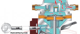
The diaphragm (membrane) is connected to the fist through a lever that is located on the throttle valve. When the valve is closed, fuel flows freely into the cavity, the suction valve opens it up. When the damper is open, the valve, on the contrary, prevents fuel from flowing out of the cavity. Air does not enter this cavity under any circumstances. Gasoline is also supplied to the sprayers through this valve. Suction occurs under the action of the spring, and discharge occurs due to the mechanical action of the lever on the diaphragm head. The accelerator pump nozzles are responsible for supplying fuel to the nozzles. One accelerator pump nozzle is routed to each carburetor chamber. The jets are installed on the same platform as the discharge valve. To gain access to the jets, you need to gain access to the carburetor chambers.
Device
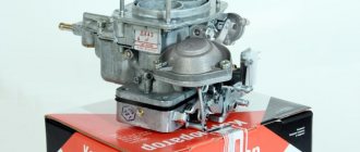
Solex carburetors are manufactured for installation on 1.5-liter engines of VAZ cars.
Solex carburetor.
Differences between SOLEKS and DAAZ:
- presence equipped with a solenoid valve that regulates the fuel supply at idle
- the presence of a heating system for the air-fuel mixture, which is connected by hoses to the engine cooling system.
The carburetor consists of a cover and a body, which includes:
Solex device.
- float chamber
- starting system
- idle system with electromagnetic valve
- main dosing system
- transition system
- econostat
- economizer with accelerator pump.
Method of folk Kulibins
Cooling system liquid pump repair
Vacuum carburetors often fail for this reason. To the question: what to do, people have long found an answer. In general, there are three solutions:
- The easiest, but also the most expensive, is to just buy a new carburetor and throw the old one in a box with garage trash, and go for a ride and enjoy the speed;
- Order and wait a long time for a part;
- Take special glue and simply seal holes or cracks in the membrane.
The third method is, of course, temporary, but with high-quality work and good materials, your membrane will last longer than the new ones from the repair kit. For gluing, we prepare a convenient place, glue, scissors and material for the patch.
We take the material for the patch. The Internet is replete with names of exotic materials. There are condoms, balloons, and surgical gloves. However, it is better to use an elastic, thinner membrane from another device. This patch will be more reliable. We cut it with scissors to the size of our part, coat it with glue.
What glue is best to use? People advise using any cyanoacrylic-based glue for gluing rubber products. We apply it to the damaged part and our patch, connect them, press and hold for a while. We leave our gluing until the glue is completely dry, assemble and install the carburetor on the scooter engine and ride with pleasure.
In conclusion, we note that all troubles with any mechanism can be solved on your own, saving time and money from the family budget.
Carburetor accelerator pump
05.02.2011
All the systems described above ensure engine operation in stationary conditions, when operating modes do not change or change smoothly. When you press the gas pedal sharply, the fuel supply conditions are completely different. The fact is that the fuel enters the engine cylinders only partially evaporated. Some of it moves along the intake pipe in the form of a liquid film, evaporating from the heat supplied to the intake pipe from the coolant circulating in a special jacket at the bottom of the intake pipe. The film moves slowly and final evaporation can occur already in the engine cylinders. With a sharp change in the throttle position, the air almost instantly takes on a new state and reaches the cylinders, which cannot be said about the fuel. The part of it that is enclosed in the film cannot quickly reach the cylinders, which causes some delay - a “failure” when the throttles are opened sharply. It is aggravated by the fact that when the throttles are opened, the vacuum in the intake pipe drops, and at the same time the conditions for evaporation of gasoline worsen.
To eliminate the unpleasant “failure” during acceleration, so-called accelerator pumps are installed on carburetors - devices that supply additional fuel only during sudden throttle openings. Of course, it will also largely turn into a fuel film, but with more gasoline, the “failure” can be smoothed out.
Fig. 12. Diagram of the economizer and accelerator pump: 1 - drive strip; 2 — accelerator pump piston; 3 - drive lever with roller; 4 - traction; 5 — accelerator pump nozzle; 6 — economizer sprayer; 7 - discharge valve; 8 — accelerator pump fuel supply channel; 9 — economizer fuel supply dripping; 10 — throttle lever; 11 — inlet valve; 12 — economizer valve; 13 — economizer pressure rod; 14 - guide rod
K-126 carburetors use a mechanical piston-type accelerator pump, which supplies fuel to both chambers of the carburetor regardless of air flow (Fig. 12). It has a piston 2 moving in the discharge chamber, and two valves - inlet 11 and discharge 7, located in front of the nozzle block. The piston is fixed to a common bar 1 together with the economizer pressure rod. The piston moves upward during the suction stroke (when the throttle is closed) under the action of a return spring, and when the throttle is opened, the bar with the piston moves down under the action of lever 3, driven by rod 4 from throttle lever 10. In the first designs of the K-126, the piston did not have a special seal and had inevitable leaks during operation. The modern piston has a rubber sealing collar that completely isolates the discharge cavity.
During the suction stroke, under the action of the spring, piston 2 rises and increases the volume of the discharge cavity. Gasoline from the float chamber through the inlet valve 11 freely passes into the discharge chamber. The discharge valve 7 in front of the sprayer closes and does not let air into the discharge chamber.
When the throttle drive lever 10 is sharply turned, rod 4 turns lever 3 with a roller on the axis, which presses bar 1 with piston 2. Since the piston is connected to the bar through a spring, in the first moments there is no movement of the diaphragm, but only compression of the spring under the bar, since gasoline filling the chamber cannot leave it quickly. Next, the already compressed piston spring begins to squeeze gasoline out of the discharge chamber to the atomizer 5. The discharge valve does not prevent this, and the inlet valve 11 blocks possible fuel leakage back into the float chamber.
The injection is thus determined by the piston spring, which must, at a minimum, overcome the friction of the piston and its cuff against the walls of the discharge chamber. Subtracting this force, the spring determines the injection pressure and implements continued fuel injection for 12 seconds. The injection ends when the piston lowers to the bottom of the injection chamber. Further movement of the bar only compresses the spring.
Category: Carburetor K-126, K-135
Previously Carburetor K-126, K-135. Economizer
Later Carburetor K-126 starting device
Symptoms of a carburetor malfunction
Many car enthusiasts think that if the car does not start, then, of course, a clogged carburetor is to blame. However, this seemingly undeniable statement is very far from the truth. Most often, the car does not start due to faulty electrical wiring in general and the ignition system in particular. If there is a spark, the starter cranks the crankshaft, but the engine stubbornly refuses to work, most likely the fuel pump is faulty or the fuel lines are clogged with air or dirt. In this case, you should not immediately blame the carburetor. If this unit is truly faulty, the following symptoms will indicate a problem:
- too few crankshaft revolutions when the engine is running in neutral gear - the engine seems to be about to stall;
- in all gears the engine stalls as soon as you release the gas pedal;
- gasoline consumption is too high: more than 12 liters per 100 km when driving in the city in the winter and more than 9 liters when traveling in the summer;
- unexpected interruptions in the operation of the power unit: the number of crankshaft revolutions when pressing the accelerator pedal suddenly decreases almost until the engine stops completely for 2-10 seconds, and then sharply increases again to the required value.
Unit repair
All of the above symptoms indicate that the VAZ Sputnik-Samara carburetor needs to be repaired. Most often, the incorrect operation of this important device is associated with excess air leaking through leaky connections and fuel lines. In second place are dirty jets. Less commonly, the cause of failure is torn membranes, springs and levers.
Return to contents
Acceleration pump
The accelerator pump serves to enrich the mixture when the throttle is opened sharply. A diagram of a mechanically driven accelerator pump, often combined with an economizer drive, is shown in Fig. 104, g. When the throttle is sharply opened, the lever 21 associated with it, through the rod 19 and the bar 18, compresses the spring 25, which moves the piston 27 down. As a result, the pressure in the well 28 increases and the check valve 26 closes, which prevents fuel from flowing into the float chamber. Through the opened discharge valve 24 and pump jet 23, fuel additionally enters the mixing chamber and the mixture is enriched.
The accelerator pump, designed for short-term enrichment of the mixture, has a mechanical drive and an adjustable flow rate. The piston rod 28 is made with grooves. The pump has a needle discharge valve 20 and a ball check valve 21. When the throttle valve is opened sharply, the piston moves quickly under the action of a spring, the discharge valve opens and fuel is injected.
A mechanically driven accelerator pump is connected in parallel with the economizer. The stroke of the pump plunger can be changed by moving the rod into the spare holes.
A mechanically driven accelerator pump is connected in parallel to the main dosing system. The specially designed throttle valve is placed on a needle bearing and is also a pneumatic speed regulator.
The accelerator pump and economizer are separate, but supply fuel through a common channel and power jet.
The accelerator pump consists of a well in which the piston moves and a valve system. The piston is moved by rod 8, which by means of rod 30 (Fig.
The accelerator pump, which is introduced into the carburetor design, allows you to enrich the mixture during the period of sharp opening of the damper and thereby eliminates the disadvantage of a simple carburetor. When the throttle valve is opened sharply, the pump piston connected to its axis quickly lowers and pumps gasoline into the mixing chamber. The mixture becomes richer and the engine quickly increases speed. In this case, gasoline cannot flow into the float chamber, since this is prevented by the check valve. If the throttle valve opens smoothly, the piston moves down slowly, the check valve remains open and gasoline flows freely into the float chamber.
The accelerator pump serves to enrich the mixture when the throttle valve is opened sharply. In this case, lever 18 (Fig. 7.3, d), connected by link 24 to rod 17, acts on bar 16 and moves piston 21 down. The fuel pressure in the pump well increases and the check valve 20 closes, preventing fuel from flowing into the float chamber. Through the opened injection valve 23 and the spray nozzle 22, gasoline is additionally injected into the mixing chamber, and the combustible mixture is briefly enriched.
| Carburetor starter diagram. |
The accelerator pump serves to enrich the mixture when the throttle valve is opened sharply and the load on the engine increases. Acceleration pumps are mechanically or vacuum driven.
| Carburetor diagram K. - 126G. |
The accelerator pump is connected by a system of levers and rods to the throttle valve drive. It has a rod with a cuff made of oil-gasoline-resistant plastic, which performs the functions of a piston.
The accelerator pump in the K-126 N carburetor operates when the throttle valves are sharply opened. In this case, the main part of the fuel under the action of piston 23, opening the discharge valve / /, is injected through the sprayer 14 into the primary chamber. Excess fuel from the pump well is forced out through the bypass hole 28 into the float chamber. The dimensions of hole 28 are selected so that when the throttle valve of the primary chamber is opened by 35, part of the fuel flows into the float chamber and is injected about one third of its volume. When the throttle valves are further opened, the bypass hole is closed by the pump piston and the remaining fuel is injected into the primary chamber.
The accelerator pump serves to enrich the mixture when the throttle valve is opened sharply and the load on the engine increases. Acceleration pumps are mechanically or vacuum driven.
| Scheme of the K-126 G carburetor. |
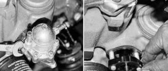
Checking and subsequent repair of the accelerator pump of the DAAZ Ozone carburetor
Before starting the test, manually pump gasoline into the float chamber and remove the carburetor cover.
The check should begin with the pump itself. By pressing the throttle drive lever, watch the stream of fuel from the nozzle. Ideally, it should be smooth and not touch the walls and axis of the damper. The timed injection should last 1-2 seconds. Problems with operation:
- The stream is weak and crooked. This means you need to clean the channels, atomizer, jets and valves;
- The injection lasts more than two seconds. This indicates a clogged bypass valve;
- Fuel got onto the hull. The diaphragm needs to be replaced or the cap needs to be secured.
Checking the DAAZ Ozone carburetor nozzles
To check the atomizer, you need to unscrew it from the housing. After unscrewing, press the damper lever. If a powerful stream flows from the hole, then the problem is in the sprayer or discharge valve. The nozzle of the sprayer can be easily cleaned with a wire, and the valve needs to be washed and blown out. The working sprayer should have a ball that makes a rattling noise when shaken.
Supply channels UN
If gasoline does not spray out of the hole when you press the throttle lever, the supply channels of the accelerator pump may be clogged. To clean them, you need to remove the diaphragm and clean the fuel supply channels with wire. They should be washed with carburetor cleaning fluid and blown out.
How to check the bypass channel together with the UN jet
When you press the throttle lever, you need to monitor the flow of gasoline into the float chamber. If the stream is not visible and the seething is not even noticeable, then the channel needs to be cleaned. At the same time, you need to wash the bypass jet. Everything is washed in the same way as other channels and blown out with compressed air.
Signs of carburetor failure
Some typical signs of engine malfunction may indicate the need to repair the carburetor membrane and other parts. These include:
Unstable engine operation occurs.
The main reason for this behavior of the engine is the pouring of a low-quality or incorrectly manufactured mixture of gasoline and oil into the gas tank.
There is a strong overconsumption of the gasoline mixture.
This nuisance entails increased carbon monoxide emissions from the engine exhaust. Very often black smoke comes out of the muffler. This symptom indicates that the fuel in the combustion chamber does not burn completely, and the combustible mixture is highly oversaturated. This may indicate a breakdown in the carburetor.
Floating speed and randomly changing tool power.
Such work will require paying attention to the tightness of the adjustment screws. Another reason may be a malfunction of the protection cap.
This may be a malfunction of the carburetor or membrane, but while searching for the causes, pay attention to the piston group of the engine and measure the compression level in the cylinder. Cleaning and adjusting carburetor parts will help for a while, but be prepared for some capital
The engine constantly sneezes and runs jerkily.
This problem usually occurs when the mixture supply channel is clogged, as well as when gasoline filters and air filters fail. In this case, flushing the carburetor with a special liquid or simple and reliable VD-40 and replacing the filters will help. As a rule, in most cases, it is enough to blow the air filter with air.
To eliminate most accelerator pump failures, the following operation may well help:
- Unscrew the screws securing the top cover. As a rule, there are 5 of them on it. Then we disconnect the damper cable to start the engine in cold conditions and twist the sprayer using a screwdriver. We clean it thoroughly using a thin soft wire or a pointed toothpick. We perform this operation several times, alternating it with air blowing. We blow it out using a pump or a car electric compressor;
- Unscrew several screws securing the camera cover and remove it. We very carefully remove the membrane along with the lever. Here you should keep an eye on the spring so that you don’t have to look for it all over the garage later. Before removing the membrane, be sure to place a piece of cloth under the carburetor to prevent gasoline from flooding the engine and exhaust manifold;
- We replace the damaged or lost elasticity membrane with a new part, install an accelerator pump and check for the presence of injection of flammable liquid into the carburetor. If the volume of gasoline is good, you can start the engine and check its operation at idle. The engine is running normally, the repair with replacement of the carburetor membrane can be considered completed.
Replacing the carburetor membrane
Video on setting up VAZ carburetors
The engine jerks at speeds above 90 km/h or does not develop the required power
air or main jet mismatch;
the second chamber does not open (most often this is a malfunction of the VAZ-2107 carburetor);
the movement of the float is disrupted, there is wear on the rod or the fuel pump itself;
large or faulty contact gaps.
Engine won't start
A cold engine may not start as a result of the following problems:
Evaporation of gasoline from the carburetor or its leakage due to poor sealing of the fuel pump valve. Before starting the engine, you must manually pump fuel to fill the float chamber.
The telescopic lever of the damper drive is stuck or stuck. In this case, the air damper does not open to the specified angle, the carburetor is overfilled with fuel and the spark plugs are flooded. To fix the problem, adjust or replace the draft and dry the spark plugs.
The air damper does not close completely. This may be due to play in the axle or binding to the housing. In this case, jamming or play should be eliminated by tightening the two screws securing the damper.
PU diaphragm breakthrough. First you need to check the condition of the PU and, if necessary, replace the diaphragm.
A hot engine does not start or starts poorly
Damage or wear of the float device valve leads to flooding of the secondary chamber. When the gas pedal is fully pressed and the starter rotates for a long time, the engine starts. To resolve this issue, install a new valve and seat.
If the engine overheats, you should allow it to cool. Then try starting again with the choke closed and the damper slightly open.
At high temperatures, the fuel pump may fail due to overheating. It is also possible for gases to form when gasoline boils in the pipeline, in the area from the pump to the carburetor. In this case, it is recommended to wrap the pump with a cold, wet cloth.
The motor trembles (twitches) in all modes
If one cylinder does not work, the engine will trip (twitch), which will lead to increased consumption and insufficient power. This situation is possible in the following cases:
burning of the exhaust valve;
failure of a spark plug due to oil entering the combustion chamber when the oil scraper rings or valve caps are too worn out leads to the appearance of blue smoke from the muffler during re-gassing;