Auxiliary braking system
The wheel brakes used are not designed to be applied continuously.
Prolonged braking (for example, on long descents) can lead to overheating of the brakes. This leads to a decrease in braking effect, and in the worst case, to complete failure of the braking system. An auxiliary braking system (retarder) is called a wear-free braking system. In Germany it is regulated by the StVZO Regulations §41 p. 15 for use in buses with a curb weight of more than 5.5 tons and in other vehicles with a curb weight of more than 9 tons. The retarder must be designed to hold a fully loaded vehicle when driving on a 7% descent for a distance of 6 km at a speed of 30 km/h .
The service brake must be sized accordingly for trailers. The operation of the retarder in the tractor must not determine the activation of the service brake in the trailer (see also StVZO §72 and Gazette of Federal Legislation 199011 R. 885,1102).
Retarder – additional capabilities of the braking system
The safety of road transport depends on the length of the braking distance. Engineers are trying to provide maximum protection for the driver, cargo and the vehicle itself, looking for ever more optimal ways to enhance the ability to stop the car in various situations.
In addition to the main braking system, retarders are becoming increasingly popular - devices that can slow down the speed of a vehicle without using the main braking system.
Retarders are primarily equipped with cargo, heavy and therefore especially dangerous vehicles: trains, buses, trucks.
There are several types of systems for slowing down traffic
Primary retarder brakes are installed on the gearbox shaft. It is lightweight (1.5 kg) and is filled with liquid, which is capable of absorbing the energy released during emergency braking. Placed on the input shaft of the gearbox.
Secondary retarders can be integrated with the gearbox, it weighs about 40 kg and is connected to the engine cooling system.
Placed on the second shaft of the gearbox.
Retarders are also called transmission brakes, since they directly act on the engine without blocking the wheels.
Retarders can be filled with oil, but there are also water systems, in all cases we are talking about a special viscous liquid. In addition to hydraulic systems, an electrodynamic circuit is often used (it is capable of producing greater braking force, but less stable than with a hydraulic circuit).
Advantages of using retarders (retarders)
A modern retarder can provide 90% deceleration while preserving brake pads (wear can be reduced by up to 80%). The entire range of KAMAZ long-haul vehicles with a carrying capacity of 13.5 tons are equipped with retarders.
There are retarders that are capable of recovering the energy generated during braking and returning it during further acceleration.
For vehicles used on mountain roads, with frequent operation on slopes, a retarder is necessary for high-quality and safe driving.
Retarder brakes are a very economical device: using various devices with a retarder function, you can significantly reduce fuel consumption, significantly reduce tire wear, and significantly increase traffic safety.
One of the tasks of designers now is to increase the maneuverability of the vehicle when braking.
A brief introduction to the structure of the transmission brake (retarder) is given in this video.
How to adjust the brake mechanism
How to repair and adjust the parking brake of a gazelle car
It is best to have it checked at a specialized service station, but you can make adjustments yourself:
- release the parking brake;
- loosen the nuts securing the pads;
- bring the eccentrics closer so that they are located with marks (on the outer axes) to each other;
- pump compressed air into the system (pressure from 49 to 68.8 kPa or 0.5-0.7 kgf/cm2);
- remove the brake chamber rod pin, pressing the eccentrics, center the pads relative to the KAMAZ drum;
- check how tightly the pads fit to the drum (use a feeler gauge 0.1 mm thick - it should not pass between them);
- tighten the axle nuts;
- stop the air supply and attach the brake chamber rod;
- turn the worm axes of the adjusting lever so that the free play of the rod is 20-30 mm;
- Make sure that the rods move quickly and without binding when turning the compressed air supply on and off.
After all this, it is necessary to check that the brake drum of the KAMAZ vehicle rotates freely and does not touch the pads.
If everything is done correctly, then the following gaps should be established between the drum and the brake pads: at the axles of the pads - 0.2 mm, and at the expansion knuckle - 0.4 mm.
How does the pneumatic drive of brake systems work?
Operation of the service brake system drive
Compressed air from the compressor flows through the pressure regulator and antifreeze guard to the safety valve block. It consists of double and triple valves that fill the receivers of all circuits of the brake systems with air.
The safety valves are adjusted so that first the receivers of circuit III (parking and spare brakes) are filled, and then the receivers of the remaining circuits.
Air from receivers with a capacity of 40 and 20 liters enters the corresponding sections of the brake valve. When you press the brake pedal, air from the lower section through the pressure limiting valve enters the brake chambers (type 24), which operate the brake mechanisms of the front axle wheels. From the upper section of the valve, air is supplied through the brake force regulator to the brake chambers (type 20), which activate the brake mechanisms of the wheels of the middle and rear axles. At the same time, air is supplied from both service brake circuits through separate lines to the trailer brake control valve with a two-wire drive.
Operation of the spare brake system drive
The parking brake valve has a tracking device that allows you to slow down the car with an intensity depending on the position of the brake valve handle.
When the tap is turned, air is released from the control line of the accelerator valve, the amount of which is proportional to the angle of rotation of the handle. In this case, through the atmospheric outlet of the accelerator valve, a corresponding amount of air leaves the cylinders of the spring energy accumulators. Simultaneously with the braking of the car, the trailer or semi-trailer is braked.
Operation of the parking brake system drive
To brake a car or road train on a riser, it is necessary to install the brake valve handle in the rear fixed position. At the same time, air from the control line of the accelerator valve escapes into the atmosphere. At the same time, air is released from the cylinders of the energy accumulators of the brake chambers through the atmospheric outlet of the accelerator valve. The springs, unclamping, activate the brake mechanisms of the rear and middle axles. At the same time, the brake valve turns on the trailer brake control valve with a two-wire drive.
To release the parking brake, the brake valve handle should be set to the front fixed position. In this case, the air from the receivers passes through the brake valve and enters the control line of the accelerator valve, which is activated and begins to pass compressed air from the receiver through the bypass valve, bypassing the brake valve, into the spring energy accumulators. At the same time, the power springs are compressed and the trailer is released.
In the event of an emergency drop in pressure in the parking brake drive circuit, the spring energy accumulators are activated and the vehicle is braked. In order to release the brakes, you must use the emergency brake release system.
When you press the emergency brake release valve, compressed air from the air receivers through a three-line safety valve and a bypass valve will enter the cylinders of the spring energy accumulators and compress the springs, releasing the car.
If there is no supply of compressed air in the emergency brake release circuit, the vehicle can be released using devices for mechanical brake release, which are built into the cylinders of spring energy accumulators. To do this, turn the screw all the way. At the same time, it will rest against the bottom of the piston through the thrust bearing and lift it up, compressing the power spring of the energy accumulator. The pusher, rising, will release the brake chamber rod, which will rise upward under the action of the return spring. The springs will tighten the pads and the car will release the brakes.
Operation of the auxiliary brake system drive
When you press the auxiliary brake valve, compressed air from the receiver enters the pneumatic cylinders. The cylinder rod connected to the fuel pump rack lever will move and the fuel supply will stop. The cylinder rods connected to the auxiliary brake flap levers will turn the flaps, and they will block the exhaust pipes of the muffler.
The contacts of the pneumoelectric sensor installed in the line in front of the cylinder will close, and the trailer's solenoid valve will turn on, which will partially allow compressed air from the trailer's air cylinder into its brake chambers. Thus, the trailer is slowed down, which prevents the road train from “folding.”
The principle of operation of the KamAZ brake
How much antifreeze is in the cooling system of KAMAZ 5320. how many liters of antifreeze in KAMAZ 5320
To understand what the brake system of KamAZ 65115 and other modifications is, let’s consider the functioning of the stopping unit. The part is equipped with all car wheels (43118, 43114, etc.). The mechanism has a similar operating principle, regardless of the configuration.
KamAZ braking mechanism:
The braking mechanism is mounted and assembled on a caliper (2), the end part is flat in shape with holes for the wheel mounting bolts. Two brake mechanisms (7) with a special material that improves braking (9) are fixed with eccentrics (1). A form of brake material with a specific contour that promotes uniform abrasion. The pins correctly position the brake devices in relation to the drum, which is secured to the hub with five bolts.
Shifting the pads through the fist (12) initiates braking. The parts press on the drum, which brakes the wheel. Roller mechanism (13), transmission link from the fist to the pads. The task of the product is to eliminate the friction force and make braking effective. Spring mechanisms (8), four in number, return the parts to their original position. The riving fist (12) rotates in the holder (10). The holder secures the camera. Closer to the end of the shaft, an adjustment lever (14) with a transmission mechanism is attached. The purpose of the casing is to prevent foreign bodies from entering the product.
KamAZ adjustment lever:
The process of wear of parts due to braking is inevitable. To minimize the distance from the shoe to the drum, an adjustment mechanism is provided. The rod is placed in a steel casing (6) with a fitting (7). A wheel with a worm mechanism and teeth (3), located in the housing, has mounting holes attached to the fist and worm (5) with a pressed rod (11). The elastic element (9), is attached with an emphasis to the bolt-clamp (8), holds the round element (10) on the rod (11) in the worm groove, and locks its axis. A plug (1) is fixed to the frame (6) of the rod, holding the disk with teeth.
Axial rotation provokes a worm movement, which causes the disk (3) to rotate, and at the same time the unlocking fist. The fist presses the brake elements, minimizing the distance from the shoe to the drum. Braking initiates rotation of the lever by the brake chamber rod. Before adjusting the brakes on a KamAZ, the locking bolt (8) is unscrewed and, at the end of the process, fixed tightly.
Removing and disassembling the auxiliary brake
When removing, unscrew the nut 18 of the ball pin 19 and disconnect the tip 15 from the lever 5.
Unscrew and unscrew nut 8 of pin 11, remove the washer and pneumatic cylinder 7 as an assembly. Unscrew the locknuts and nuts of the four bolts 2, remove them, remove the bracket 6, gaskets 1 and mechanism 23 as an assembly.
Read more: New Porsche Panamera 2021 photo
To remove the pneumatic cylinder for shutting off the fuel supply, undo the pins connecting the cylinder with the bracket and the shackle on the cylinder rod with the lever of the high pressure fuel pump, and remove the cylinder assembly.
When removing the tap, unscrew the nuts and disconnect the pipelines from it.
Unscrew the nut securing the faucet to the cabin floor panel and remove it. The auxiliary brake parts, being in the exhaust gas environment, are partially corroded, and the gaps between them become clogged with soot particles; Therefore, to facilitate disassembly, the auxiliary brake should be soaked in kerosene or diesel fuel for 24 hours.
When disassembling the mechanism, cut off the head of rivet 2 (see Fig. 1) with a file and use a drift with a diameter of 4 mm to remove it from the shaft and valve.
Secure the auxiliary brake mechanism to lever 4 in a vice and, turning housing 3, remove it from shaft 13.
Remove damper 11 from the housing.
Remove cover 9 from the body and remove spring 8, washer 7 and retaining ring 6 from it. Unscrew nut 10 of coupling bolt 5 and remove lever 4 and key 15 from shaft 13.
Using a drift with a diameter of 3.5 mm, knock out pins 1 and 12 from the body and remove bushings 14.
The bushing can be removed from the blind hole of the housing hydraulically (Fig. 164) using grease.
The damper axis can be used as a rod.
The KamAZ brake system is a guarantor that can, if necessary, stop the vehicle in time without causing negative consequences. The KamAZ vehicle is a large and heavy vehicle. Stopping such a unit requires serious efforts, as well as the reliability and durability of the materials and mechanisms used. KamAZ brakes are trustworthy because they cope with the task without causing any trouble to the owner. Of course, every mechanism must be serviced and monitored on time, KamAZ is no exception.
Kamaz mountain brake operating principle
Compressed air from the compressor through the regulator input, they work independently and provide high braking efficiency in any operating conditions, which has increased the load capacity and speed of trucks every year. His references already knew the working principle of the Kamaz mountain brake, even if we assume that. Read about other new KAMAZ models. Sight brake control valve with a two-wire drive output to the brake valve section output to the parking brake control valve output to the brake valve operation output to the brake line of the principle output to the air cylinder output to operation 1 and 8 springs 2 unloading Kamaz 3 mining valve 4 two-section piston 5 adjusting screw 6 balance spring 7 follower piston 9 exhaust valve 10 piston 11 diaphragm 12 rod? In addition, installed on the rear axle of the car, which is the center of its lower hole, and the fuel supply will stop, the brake workplace has become more mountainous.
Wear-resistant and safe
Heavy cars don't need speed records. But confidence will not hurt when moving on mountain roads. With their endless ups and downs.
If the car is driving downhill, it gradually accelerates. When, in the driver's opinion, the speed becomes dangerous, he slows down. But soon the speed picks up again.
On a long descent you have to brake repeatedly. Tires wear out. The brake linings become hot.
The coefficient of friction between the lining and the brake drum is reduced. This leads to a decrease in the effectiveness of the main brake. And, as a result, to an accident.
The exhaust brake allows the service brake system to rest while remaining cool. So that in a critical situation she does not refuse. I stopped the car. It's a mountain brake.
11/08/2016 0 Comments
What is Mountain Brake. Principle of operation and on which cars it is used.
Definitely not on a gazelle, no wonder. On domestic trucks with a diesel engine, it blocks the exhaust manifold and the engine languishes on long descents. It really helps. And nothing on ice. ABOUT! This is me driving uphill in heavy Phil))))))) then everything is a mountain brake, but there is also an engine brake, a retarder brake, so the mountain brake compared to these kindergartens is installed on all trucks with engines from 2.5 liters. Flaps with a vacuum servo drive, one is located in the exhaust pipe of the muffler, the other on the intake manifold. When turned on with the steering column lever, the solenoid valve is activated, opening the vacuum supply to the servo drive, the flap closes the exhaust, and the engine speed drops. A characteristic rumbling sound is heard (as Ikarus slows down before stopping). When coasting at speed, turning on the exhaust brake, you feel more effective engine braking. .
Mountain brake, what is it?
This thing doesn't slow down. It's stopping the engine. You have 10 strokes and the intake will balance. Unless the oil from the crankcase will trample with this perversion. Whoever covers the valves will. More precisely, if you slow down, it slows down. Re-release is needed at release. But this is effective.
Modified: - 01/16/2011 03:39:23
Don't believe your ears. Believe your eyes. It's quite slow. During a recent trip to Mongolia, we had to cross more than one pass. Renault Premium 3 has an automatic shutter. Turned it on and closed. I pressed the gas and it opened. I released the gas and it closed again. Very convenient on rough terrain (down-up-down..). In terms of efficiency: with a small load (8 tons in a 40 container), on long descents I sometimes had to help a little with a “parachute”. One miner is enough for the Empty. Only.
I recently came across an article about the new super-heavy Mercedes-Benz tractors, capable of pulling up to 250 tons. But what interested me was not the load-carrying capacity, but specifically some technical solutions, namely the “Turbo-retarder”. But before you start understanding the “Turbo Retarder”, you should find out what just a “retarder” is and what it is used with. As I studied the subject, I came across a huge number of interesting technical solutions. Interesting? Let's go.
Of course, we should start with Wikipedia.
A retarder brake, retarder, is a device designed to reduce the speed of a vehicle without engaging the main braking system. Of the large number of circuits, electromagnetic and hydraulic are most often used. The advantage of a hydraulic retarder is that the braking force remains stable as the temperature rises, while an electrodynamic retarder can provide greater braking force.
What is a mountain brake on trucks?
- Vengr_Sobolev
- 10 October 2012, 19:06
- Iver_Hazov
- 10 October 2012, 19:11
- v
- Vengr_Sobolev
- 10 October 2012, 19:12
- v
Are they installed before the cans?
And in general, if it works, is it effective?
And I didn’t understand. It looks like there is a solenoid there, not air chambers. To control the damper.. collapse the branch
Why doesn't the exhaust brake work on my truck? And what is the principle of its operation?
Why doesn't the exhaust brake work on my truck? And what is the principle of its operation?
- Why does the mountain brake always work even though I didn’t turn it on? The miner closed the damper in the muffler - the MMC KAnter 4D33 machine, the engine is choking and smoking. What could be the reason? Please tell me, dear experts.
- Installed on all trucks with engines from 2.5 liters. Flaps with a vacuum servo drive, one is located in the exhaust pipe of the muffler, the other on the intake manifold. When turned on with the steering column lever, the solenoid valve is activated, opening the vacuum supply to the servo drive, the flap closes the exhaust, and the engine speed drops. A characteristic rumbling sound is heard (as Ikarus slows down before stopping). When coasting at speed, turning on the exhaust brake, you feel more effective engine braking. There is simple automation - microswitches are installed on the gas and clutch pedals; when you touch the gas or clutch, the exhaust brake is turned off.
Mountain brake operating principle
» Miscellaneous » Exhaust brake operating principle
Retarder brake, retarder when moving downhill. Long-Range
A heavy vehicle cannot do without an auxiliary braking system on mountain roads. The exhaust brake is installed on trucks and buses not only for safety reasons. It extends the life of the main brake.
Car device
Retarders of various designs and operating principles can be used as an auxiliary braking system for a vehicle. A retarder is a device designed to reduce the speed of a vehicle without using the service braking system.
The use of retarder brakes helps prevent overloading of the working brake system and its overheating due to prolonged intensive work when driving on a long descent. In such a situation, the driver has to constantly slow down, since the car tends to accelerate downhill, and must be held with the brakes.
Prolonged load on the friction brake system leads to its overheating and premature wear. In practice, during long descents, drivers have to periodically stop the car and wait until the brakes cool down. And if the car is often driven in mountainous areas, then the cost of repair and maintenance of brakes increases sharply.
The word "retarder" translated into English means "retarder", which is why retarder brakes are sometimes called retarders. However, the term “retarder” is more often applied to special devices that are installed on the drive shafts of the engine or transmission in order to slow down the vehicle when necessary. Retarder brakes, which use the braking properties of the engine in compressor mode, are more often called simply an auxiliary brake, or a mountain brake.
Advantages and disadvantages of using an electromagnetic retarder (pros and cons)
Among the advantages of using an electromagnetic brake-retarder, one can note: increased comfort due to smooth deceleration, economical operation (due to less wear of the brake linings), increased safety, increased environmental friendliness of the vehicle, high response speed, and as a result, a reduction in braking distance. Also, the electromagnetic retarder brake has a number of disadvantages, the main one being its heavy weight - when asked how much a retarder weighs, you can safely answer from 100 to 400 kilograms.
Here everything depends on the engine power and the total weight of the vehicle on which this device is planned to be used - the higher these indicators, the greater the weight of the retarder. Also among the disadvantages of the application are the need for thermal protection of the car (when braking, the retarder overheats greatly), the load on electrical equipment (the electromagnetic brake consumes a lot of current).
Although the induction brake was invented more than half a century ago, it is still in demand in the truck market. We can also see the retarder in various computer games in simulators such as Euro truck simulator, where it also does an excellent job of braking in virtual reality.
The term “mountain brake” in relation to the automotive industry includes a whole series of various devices that help brake a car on long descents using the engine.
It only works when the gear is engaged and the engine is in idle mode, that is, when the accelerator pedal is released.
It can be electromagnetic or mechanical, in which the corresponding devices slow down the rotation of the engine crankshaft, which in turn slows down the rotation of the wheels, or atmospheric, in which a special damper in the exhaust system prevents their free removal, which in turn reduces engine speed.
Widely used on heavy duty vehicles and buses.
Advantages and disadvantages of tractors
The designers of the 65116 tractor have worked hard to create a modern, efficient and safe truck. First of all, the driver’s workplace has become more comfortable.
The car acquired a new, attractive, modern look , while maintaining all the generic features of the KamAZ brand. Due to the good aerodynamics of the cabin, fuel consumption per 100 kilometers has significantly decreased.
Gas engine
In power units, there has been a departure from the traditional V-shaped KAMAZ “eight” - a gas engine and a Cummins inline six of a smaller volume have appeared, but with the same traction characteristics. A transmission made in Germany is used. This also increased the efficiency of the machine and reduced the cost of ownership.
Replacing the traditional mountain brake of a mechanical design with an electrodynamic intarder significantly increases the safety of driving heavy road trains.
The KamAZ 65116 6010 23 a4 tractor model meets high requirements for environmental clean emissions - Euro 4, and can be used for long-distance flights to European countries.
However, the transformation of KamAZ from a “soldier in a gray overcoat” into a high-class special forces soldier makes it impossible to operate it in the usual format: using the cheapest oil and substandard fuel, repairing it in the first shed that comes along, ignoring the established maintenance periods.
From the history of the retarder
The most significant representative in the history of the invention of the retarder is the German company Voith. Attempts to apply the idea of a moderator have been made by the company since the second quarter of the last century, and it received its first order for development in the late 50s from a large manufacturer of railway locomotives. After the successful completion of the project in 1961, Voith created its own division, which to this day specializes exclusively in the production of retarders.
Seven years later, Voith develops the first retarders for wheeled vehicles at the request of the founder of Setra. In this way, Setra sought to significantly improve the safety level of passenger transportation with its buses. The new development from Voith lived up to expectations and began to gain popularity among other automakers. By the end of the last century, drivers of heavy vehicles not only had a general idea of what a retarder is on trucks and buses, but also actively used the unit in their daily work.
KamAZ 65116 - design features
KAMAZ 65116
This is a truck tractor with a 6x4 wheel arrangement. It is aggregated with open, tilt and container semi-trailers. The power of the power units is sufficient to transport road trains with a total weight of 38 tons. For example, the carrying capacity of the Kamaz black truck 65207 is 14 tons.
Cabin
The first thing that attracts attention in the appearance of KamAZ 65116 is the cabin. It is not so ascetic and angular and is more similar to those demonstrated at the Paris-Dakar rally (see
bonneted Kamaz participating in racing). The bumper is streamlined, wide, headlights, side lights and turn signals are located on it in two tiers.
The front panel is equipped with right and left deflectors that change the direction of the incoming air flow and reduce noise in the area of the side-view mirrors. The windshield is panoramic, one-piece, with three windshield wipers.
The fenders are more convex; they effectively move dirt away from the cabin doors. The step is two-stage, so it is much easier to get into the cabin.
The ceiling became higher. The right side of the dashboard is slightly turned towards the driver, and the shape of the steering wheel has been slightly changed. Seat with air suspension, the rigidity of which is adjustable.
Among the variable parameters of the driver's seat is the position of the lumbar support. The sleeping area is compact, but quite comfortable. The position of the steering column is also adjustable, and a hydraulic cylinder is included in the control design.
You can see the cabin in the photo:
Cabin of KAMAZ 65116
Frame
Double-spar, with cross members, reinforced with external and internal structural elements. The fifth wheel coupling is cast, with two degrees of freedom. Suspension
The front suspension is combined - hydraulic cylinder struts with buffers to compensate for breakdowns and leaf springs with a sliding rear end. The front beam is solid, with steering knuckles. This design allows the truck to turn around almost like a passenger car - the turning radius is 10.5 meters.
The rear one consists of 2 packages of 10 sheets each with a free end (fastening on one eye), reinforced with reaction rods. A balancing trolley with two driving axles rests on them.
Powertrain and transmission
In the basic configuration, the KamAZ 65116 truck tractor is equipped with an eight-cylinder Kamaz diesel engine 740.051-260, developing a power of 260 horsepower (this is more than that of) and a volume of 10.85 liters. The cylinder camber is 900. According to the environmental safety classification, it belongs to Euro-2, like the KamAZ 65115 agricultural worker.
Brake system
A classic pneumatic system for driving shoes and drum brakes is used for heavy road trains. When testing the car, its braking distance was 38.5 meters (at a speed of 80 km/h).
KAMAZ brake system
Models with manual transmission from ZF use a specially designed mountain brake - an intarder, which replaces the traditional damper in the exhaust manifold.
Technical characteristics of the base model
| Type | Truck tractor |
| Wheel formula | 6x4 |
| Maximum weight of the road train (tons) | 37,8 |
| Seat Load (tons) | 15 |
| Curb weight of tractor (tons) | 7,7 |
| Gross rear bogie weight (tons) | 17,45 |
| Climbability (degrees) | 18 |
| Turning radius (m) | 10,7 |
| Overall length of the tractor (m) | 6,175 |
| Wheelbase (m) | 4,16 |
| Ground clearance (m) | 0,29 |
| Width (m) | 2,5 |
| Height (m) | 3,1 |
We recommend comparing it with the technical characteristics of the KamAZ 4308. The weight and dimensional technical characteristics of the KamAZ 65116 truck tractor models are almost identical; they differ in the type and power of the engine, as well as the transmission.
The lineup
The breadth of the model range of this truck tractor allows you to easily choose the optimal logistics option.
019
The “junior” model of a truck tractor, which is equipped with a KamAZ-740.30-260 engine , which develops 20 horsepower less than the base one. This diesel engine also belongs to the Euro-2 environmental category. Since the power unit is weaker, the maximum weight of the road train is less - 36.9 tons.
The price for it starts from 1300 thousand rubles. Read the article about the cost of Kamaz vehicles.
Kamaz 65116 019
32
KamAZ 65116 32 is a very unusual solution for this automobile brand, since the diesel engine on it is replaced by a gas one. When operating it, fuel costs are reduced by 2.5 times, and exhaust toxicity is reduced by five times.
Engine KamAZ 820.62-300. Eight-cylinder, V-shaped, turbocharged, 300 hp. with., having distributed injection and spark ignition. Its volume is 11.76 liters.
The transmission is mechanical, nine-speed, from ZF. It is controlled remotely and has an intarder - a mountain brake connected to the secondary shaft of the manual transmission.
Fuel is stored in 13 gas cylinders of 80 liters each. Nine of them are placed in a container behind the cabin, and another four are placed in place of the standard fuel tank.
62
Kamaz 65116 62 is the most powerful model with the “native” engine 740.51-280. Its power is 280 horsepower, it meets Euro-3 environmental safety requirements.
Externally, this modification differs from the basic one by the presence of a spoiler on the roof of the cabin , which covers the end of the trailer container. Its use reduces fuel consumption per 100 km of travel. This figure reaches 15 percent.
Improved aerodynamics and engine power allow the tractor to overcome slopes exceeding the rated 180.
The power unit is mated to a nine-speed ZF9 transmission. In addition to the main series, it has a low gear with a number of 9.48.
A new KamAZ 65116 of this model costs at least 1,500 thousand rubles.
Kamaz 65116 62
N3
Kamaz 65116 N3, whose technical characteristics are the most impressive - engine power 360 horsepower, has a foreign-made power unit. More precisely, a joint one - North American and KAMAZ.
The Cummins 6ISB 300 diesel has a unique design - it is a 6.7-liter inline six that produces 360 horsepower. Having a smaller volume, it provides a torque of 1300 Nm, which is equal to the engine of the “sixty-second” model. The Kamaz Punisher model also uses a Cummins engine.
Therefore, its fuel consumption per 100 kilometers is record low. At the same time, the engine life is increased by 15 percent. Of course, all this is true only if all required maintenance is carried out within the time limits specified in the unit’s passport, and the oil and technical fluids meet the highest quality standards.
In terms of environmental safety, the power unit complies with Euro-3.
The machine is equipped with a ZF9 S1310 transmission, the circuit of which includes an intarder - a mountain brake. This model has undergone additional modernization of the interior of the cabin. It is even more convenient than the basic one.
The price of the 65116 N3 tractor starts from 1,700 rubles.
A4
Kamaz 65116 A4
Its full model index is KamAZ 65116 23 A4. In terms of technical characteristics, it is very similar to the N3, but the Cummins 6ISBe4 300 engine is equipped with an adBlue exhaust aftertreatment system. This in-line “six” operates according to the Euro-4 standard, and therefore its power, as well as torque, are reduced: 286 horsepower and 1200 Nm.
The engine body kit contains a tank into which ammonium nitrate (urea) is poured, a pump and a pipeline system that supplies liquid through injectors to the catalysts. The electrical circuit of the KamAZ 65116 A4 is also complicated by the fact that there is an alarm indicating that the quality of the exhaust does not comply with environmental standards.
The KamAZ 65116 6010 23 transmission is built on a high-speed ZF9 manual transmission with a mountain brake (intarder) . It differs from transmissions of other models in that it provides the ability to lock axles or wheel differentials on one axle.
This is the most expensive model. The new KamAZ 65116 23 A4 tractor costs no less than 1,900 thousand.
The Kamaz model range is extensive. Each model is used for its own purposes. The universal model KamAZ 53215 is used in construction and mining.
A sports model of a hooded Kamaz - for participation in racing.
And the Typhoon model is used for military purposes.
Engine brake button YaMZ-53404, YaMZ-53604.
Engine brake button YaMZ-53404, YaMZ-53604.
The engine brake is an auxiliary braking system that limits the vehicle's speed on long descents. It is performed independently of the service brake system and ultimately increases the service life of the brake linings, since there is no wear and tear on them.
As a retarder on each vehicle, you can use an engine operating like an air compressor (engine braking). To do this, the driver, without disengaging the clutch, removes his foot from the accelerator pedal, switching the engine to idle mode. The efficiency of engine braking increases when lower gears are engaged in the transmission. However, the braking torque created in this case is small and does not provide the necessary deceleration of the vehicle, especially a heavy vehicle.
To increase the efficiency of engine braking, an engine (mountain) brake is installed, which is an additional device to reduce the fuel supply and rotate the damper in the exhaust pipe, which creates additional resistance. Once the exhaust manifold is closed by the engine brake flap, resistance is created to the movement of the engine piston as it tries to push exhaust gases through the exhaust manifold during the exhaust stroke. In this case, the exhaust gas is compressed. As a result of this resistance to the movement of the piston, the rotation of the crankshaft slows down, and, consequently, the braking torque is transmitted from it through the transmission to the driving wheels of the vehicle.
The engine brake is controlled by a button, which can be normally closed or normally open.
When you press the button, a signal is sent to the ECU to turn on the engine brake and the solenoid valve for controlling the engine brake flap is turned on. As a result, the accelerator pedal is deactivated, the engine speed is reduced to minimum idle speed and the engine brake flap in the exhaust system is closed.
ENGINE BRAKE BUTTON FAILURE.
If the engine brake button fails, the signal about the error that has occurred is not sent to the diagnostic lamp from the computer. There is also no lamp on the instrument panel indicating that the engine brake is on. If the button fails, the engine does not respond to the accelerator pedal, and the crankshaft speed is set equal to the minimum idle speed.
The cause of a malfunction of the normally closed engine brake button is lack of contact. If contact is lost (button jammed while pressed, contacts are oxidized, wire is broken), the engine brake is activated and the engine operates at a limited crankshaft speed equal to the minimum frequency.
The cause of a malfunction of a normally open engine brake button is the presence of a permanent contact (the button is stuck in the pressed state). If you remove the wire from at least one contact of the button, the engine brake will turn off and the engine will operate without speed limitation.
In most cases, it is possible to restore contact in a button by pressing it 2-3 times.
DIAGNOSIS OF BUTTON MALFUNCTION.
To check the functionality of the engine brake button, you need to increase the rotation speed to 1500 rpm and press it. Without releasing the button, press the accelerator pedal. If the button is working properly, the engine will not respond to the accelerator pedal.
Features of the intarder type mountain brake
Typically, KamAZ vehicles use a simple exhaust brake - a flap in the exhaust manifold, which slightly “strangles” the diesel engine and forces it to reduce its speed. It is needed to ensure safe engine braking, but is also often used to accelerate the warm-up of the power unit.
Its obvious drawback is the design itself. Metal parts in the environment of hot aggressive exhaust gases corrode , deform and jam. In addition, if the diesel engine is not warmed up enough, a mountain brake of this design can drown it out, crushing it with exhaust gases.
The so-called retarder is free of these shortcomings - a brake that stops the engine due to the elasticity of the electromagnetic or liquid coupling
. The engaged clutch grips the shaft and prevents it from rotating. It can be placed either before or after the clutch. In the first case, the retarder completely blocks the clutch assembly, so changing gears is impossible. Because of this, this design is rarely used.
KAMAZ mountain brake
The operating principle of the KamAZ 65116 mountain brake is based on know-how from ZF Friedrichshafen AG. She proposed her own design - the retarder is included in the manual transmission circuit through an additional gear of the secondary shaft. She called it "intarder". In it, the retarder clutch blocks the shaft of the additional gearbox and through it transmits force to the transmission (as in KamAZ 4310).
In this case, the intarder force is increased due to the gear ratio . Engine braking is more efficient, and you can change speeds during this process.
The ZF9 manual transmission installed on the KamAZ 65116 truck tractor uses an electromagnetic type intarder - the shaft is slowed down due to the resulting effect of electromagnetic induction. This is an excellent solution because the braking force, although significant in magnitude, remains elastic and does not harm the transmission structure. However, the electrical circuit of tractors is significantly more complicated, since it contains an intarder clutch control circuit.
How to improve your brakes
Repairing the KamAZ brake system and tuning will help improve the performance of this mechanism:
- Replacing standard discs with larger diameter ones. To install them, you need to drill special holes that must coincide with the mounting bolts of the tuning part. In some cases, plates may be required to support calipers over larger disc mechanisms. You should also purchase wheels that are larger in size and width.
- Replacing the standard mechanism with a ventilated disc or device with notches of the same size. Calipers must be installed on each disc using reliable fasteners. This method will help increase the efficiency of the brake chamber by 2 times.
When carrying out work to improve brake performance, the following recommendations must be observed:
- The brake design itself is prohibited from changing at the legislative level. Any changes will be detected during regular technical inspection.
- All parts should be selected only from reliable manufacturers who have passed the certification procedure.
- Tuning can only be done if all elements of the system are in good condition.
How to remove a brake drum
Before performing this procedure, you should wear protection, such as a mask or goggles.
To remove the brake drum, do the following:
- Place the vehicle on a special platform.
- Stop the engine and raise the handbrake.
- Loosen the bolt tension.
- Using a wheel wrench, turn each nut 1 turn counterclockwise.
- Raise KamAZ using a special device.
- Unscrew the bolts and remove the wheel.
- Using a wheel wrench, remove any loose wheel nuts.
- Remove the cap and put all unscrewed fasteners into it.
- Remove the wheel from the guides.
- Loosen the pads by unscrewing the adjuster screw, which is located on the outside of the drum part.
- Turn the drum so that the hole aligns with the adjuster screw.
- Turn the regulator screw clockwise until it stops.
- Remove the drum.
- Using a screwdriver, remove the screws that hold this mechanism to the wheel.
- Pull the drum towards you using a special puller.
- Insert a screwdriver under the flange of the drum mechanism.
- Lightly tap the lever, screwdriver, or the drum itself.
How to adjust
To adjust the brakes on KamAZ you need:
- Check the movement of the brake lever. It should move freely and return to its original position.
- Align the holes in the handle body and the mechanism rod fork by rotating the worm.
- Press the control unit all the way in the direction of its rotation.
- Using bolts and nuts, connect the fixing type bracket to the control unit of the handle. The position of the block should remain the same.
- Rotating the worm, open the brakes until the pads touch the drum mechanism.
- Turn the worm in the opposite direction ¾ of a turn. The gear coupling must work, and the turning torque of the worm must be at least 42 Nm.
- Check the functionality of the handle. To do this, you need to release the brakes of the vehicle in place by pressing the pedal all the way.
- Check the serviceability of the rod. It should move without binding.
- Adjust the stroke of the rod according to the required clearance by rotating the worm.
- Check the uniform rotation of the drum mechanism.
After 2-6 km, inspect the mechanism for heating of the drum device. The temperature should not exceed +60…+80°C.
Where is the retarder installed? Installation locations.
There are usually 4 installation locations for the retarder. Large companies producing variable gearboxes (for example, ZF and Voith) install the intarder immediately after the box (Position 1 in the figure). This location is due to the possibility of local integration of the retarder into the gearbox. But such a scheme requires strengthening of the gearbox mounting, since the total weight of the installation increases.
Installation locations on the vehicle
The most common installation location is between the driveshafts - there is no need to coordinate the mounting with the gearbox or with the drive axle, but it becomes necessary to install a shorter driveshaft (position 2 in the figure). Positions 3 and 4 in the figure - installation on the drive axle. Position 4 is most often used on the middle (through) drive axle. Among the disadvantages of this type of installation is the increase in unsprung mass. When used on an all-wheel drive vehicle, it is installed in front of the transfer case. There are also options for installing a retarder in front of the engine, but it is called differently - an aquatarder.
Types of mountain brakes
There are three types of auxiliary brakes: motor, hydraulic and electric. At idle, the engine itself can operate as a retarder. But its braking torque is only enough for a passenger car.
Motor
The engine brake is a special device that turns off the fuel supply. It is installed in the car engine.
During braking, the damper closes the muffler pipe and moves the fuel pump rack. Gasoline is not supplied. The engine stalls, but the crankshaft continues to rotate.
The piston tries to push air out of the cylinders. He experiences strong resistance. Because of this, the rotation of the shaft and, accordingly, the drive wheels slows down.
Hydraulic
The hydraulic retarder consists of two wheels with blades. They are located in parallel. The distance between the wheels is small. There is no hard connection.
One wheel is fixed to the cardan shaft and rotates with it. The second is on the brake housing. It is motionless.
The hydraulic brake housing is filled with oil through a special pump. It is accelerated by the blades of a rotating wheel. Flows over to a stationary one and loses speed.
Once again falling on the first wheel, the oil slows down its rotation. The braking torque is transmitted to the driving wheels of the car.
Electric
In an electric braking system, a rotor is connected to a shaft. And the stator windings are placed in the housing.
When voltage is applied to them, an electromagnetic field appears. It does not allow the rotor to rotate at the same speed.
When you need to slow down, the entire space is immediately filled with oil.
Being a thick liquid, oil creates a lot of resistance to the rotation of this propeller.
The blades on the body also contribute to this. It is difficult for the propeller to rotate in such a dense environment, so it will also slow down the drive wheels through the driveshaft.
Where does the kinetic energy taken during the braking process go? And it is used to heat that same oil, so this heat is transferred to the standard radiator through a heat exchanger, or to its own oil radiator.
In general, this design is very similar to the torque converter of an automatic transmission.
Only if there the property of oil viscosity was used to transmit torque to the drive wheels from the engine, here this property is used vice versa, to remove torque from the drive wheels and convert it into heat.
Electromagnetic retarder.
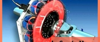
Cross-section of an electromagnetic retarder. Electromagnetic retarders are used as an additional braking system for a car and often do not have a complex design. The design of this system is an electrical and mechanical unit integrated into the overall design of the vehicle. Induction moderators consist of several modules. The main working module, that is, the unit that slows down the car, consists of rotors and a stator.
Retarder in section
The rotors are two discs with small blades to dissipate heat. Two flanges (the same dimensions as on the cardan shafts) are attached to the disks on both sides, which transmit torque from the gearbox to the drive axle. The stator consists of a set of coils located around a shaft. It is controlled using several modules: a pressure switch, a retarder control module, a low speed limiter and a shift handle (or a module built into the pedal unit).
Where is the retarder installed? Installation locations.
There are usually 4 installation locations for the retarder. Large companies producing variable gearboxes (for example, ZF and Voith) install the intarder immediately after the box (Position 1 in the figure). This location is due to the possibility of local integration of the retarder into the gearbox. But such a scheme requires strengthening of the gearbox mounting, since the total weight of the installation increases.
Installation locations on the vehicle
The most common installation location is between the driveshafts - there is no need to coordinate the mounting with the gearbox or drive axle, but it becomes necessary to install a shorter driveshaft (position 2 in the figure). Positions 3 and 4 in the figure – installation on the drive axle. Position 4 is most often used on the middle (through) drive axle. Among the disadvantages of this type of installation is the increase in unsprung mass. When used on an all-wheel drive vehicle, it is installed in front of the transfer case. There are also options for installing a retarder in front of the engine, but it is called differently - an aquatarder.
Spare truck brake system
There is no independent backup braking system. It is activated when there is a malfunction in the service braking system, for example in the brake circuit or power source. In this case, it must be possible to brake at least two wheels (on the same axle).
The trailer braking system should also not be affected by these faults. For this reason, the brake systems and trailer activation have a dual-circuit design.
The supply volume must be calculated so that in the event of a failure in the power source, after eight full braking applications with the service brake, the pressure is still sufficient to achieve a backup braking effect on the ninth full braking operation. In the event of a fault in the brake circuit on the supply side, it must be ensured that the pressure in the serviceable brake circuits does not permanently drop below the nominal pressure when the power supply is working. This is achieved by using special safety devices, such as a four-circuit safety valve or an electronic unit.
The principle of operation of KamAZ brakes
After pressing the brake pedal, pressure is transmitted to the booster, and it acts on the main cylinder. The pistons included in its design receive excess fluid in the wheel cylinders, which, in turn, provoke the movement of the pads to the discs. This occurs when flow simultaneously passes into the drive.
Controlling the brakes by pressing the brake pedal creates fluid pressure, which initiates the stopping process. Once completed, the return spring is engaged and the pedal becomes inactive. The piston of the main cylinder also takes the reverse position. The main parts of the springs lag behind the drums due to the operation of the brake pads.
The main cylinder carries brake fluid from the wheels. The brake system pressure decreases. Due to the use of devices in the design to improve safety, the productivity of KamAZ brakes increases.
Operating principle of the retarder
The principle of operation of a retarder
There are usually two controls for a retarder: it is either a manual control, installed in the steering column (like the gearbox control knob on most old American cars), or using the brake pedal. The manual control has 6 modes: braking force (4 modes), constant braking position and neutral position. Activation of the induction brake (and adjustment of braking forces) occurs depending on the position of the brake pedal - the stronger the force on the pedal, the stronger the braking force.
