Published:
21.03.2017
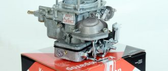
Initially, the VAZ-2106 car left the factory with an Ozone carburetor. However, this unit has so many shortcomings that with the advent of the more modern Solex carburetor, many owners of classic Zhiguli cars could not resist the opportunity to improve the engine of their car. Among most of them there was an opinion that this would improve the technical characteristics of the car, while others believed that this decision would have a detrimental effect on the stability of the engine. In this article we will look at what advantages such a modernization has and, if any, how to install and adjust the Solex carburetor on a VAZ-2106 car with your own hands.
With the “native” carburetor, the engine of the “sixth” model had good throttle response. But there was also a significant drawback in the form of failures when trying to sharply increase the crankshaft speed. That is, as soon as the driver pressed the gas pedal, the engine first “choked” and only then began to gain momentum. The reason for this is the insufficient fuel level in the float chamber, which affected during intensive acceleration of the car. That is why the owners of the “sixes” wondered about the possibility of installing an alternative carburetor that could increase the engine’s throttle response with minimal losses. The choice fell on the Solex unit as the best option.
Initially, the six was equipped with an OZONE carburetor
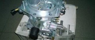
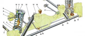
Purpose and design of the VAZ 2106 carburetor
The VAZ 2106 car began production in 1976 and immediately gained great popularity among domestic car enthusiasts. To keep the small engine running smoothly, it required air, fuel, a powerful spark, and compression. The first two elements are mixed in a carburetor, designed to prepare an optimal fuel-air mixture. On the VAZ 2106, the manufacturer installed an “Ozone” carburetor produced by the Dimitrovgrad Automotive Assembly Plant (DAAZ).
On the VAZ 2106, the designers installed an “Ozone” carburetor manufactured by DAAZ
The operation of the device is based on the principle of jet propulsion. A powerful jet of air through the jets located in the diffuser carries fuel from the float chamber. As a result, a fuel-air mixture is formed in the proportions necessary for its ignition in the combustion chamber.
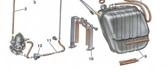
The carburetor consists of three main parts:
- The upper section is a cover with a damper to regulate the flow of air into the combustion chambers. Using a system of channels, it is connected to the throttle valve and the float chamber.
- The middle section consists of diffusers, fuel nozzles and a float chamber. The diameters of the jets are shown in the table.
- The lower section includes the throttle valves of the two chambers.
Table: calibration data for the Ozone carburetor
| Parameter | First camera | Second camera |
| Diameter, mm | ||
| diffuser | 22 | 25 |
| mixing chamber | 28 | 36 |
| main fuel jet | 1,12 | 1,5 |
| main air jet | 1,5 | 1,5 |
| idle fuel jet | 0,5 | 0,6 |
| idle air jet | 1,7 | 0,7 |
| econostat fuel jet | — | 1,5 |
| econostat air jet | — | 1,2 |
| econostat emulsion jet | — | 1,5 |
| air jet of the starting device | 0,7 | — |
| throttle valve pneumatic drive jet | 1,5 | 1,2 |
| accelerator pump nozzle holes | 0,4 | — |
| accelerator pump bypass jet | 0,4 | — |
| Accelerator pump flow for 10 full strokes, cm3 | 7 ± 25% | — |
| Calibration number of the mixture sprayer | 3,5 | 4,5 |
| Emulsion tube calibration number | F15 | F15 |
Any deviation in the composition of the fuel-air mixture from the optimal one affects engine performance. It becomes difficult to start a cold and warm engine, its operation at idle and in operating mode is disrupted, and acceleration dynamics deteriorate.
Carburetor diagnostics after adjustment
Now you need to make sure that all settings are set correctly. To do this, you need to start the engine and watch it idle. Is he starting to trip? Next, press the accelerator sharply and also sharply release it. Can you hear any dips? If yes, the fuel quality adjustment screw needs to be unscrewed a little.
During heavy braking, the engine should continue to operate stably. If it stalls, you need to slightly unscrew the quality screw.
Thus, you now know how to adjust the carburetor on a VAZ 2106 on your own without special tools.
Experienced carburetor technicians! If you find inaccuracies in the article and want to share your experience, write your comments. Your opinion will be very useful to all readers of the site. Sixes are often equipped with DaAZ and Solex carburetors. Is there a fundamental difference in adjustment between them? Also interested in your opinion.
This article is part of a series of 9 lessons dedicated to 7 carburetors. To view all nine lessons, follow the link: https://7vaz.ru/chto-takoe/karbyurator.html
Source
VAZ 2106 carburetor maintenance
During the operation of the carburetor, the narrow channels of the jets become clogged. This usually happens when using low-quality fuel, untimely replacement of the air filter, etc. The composition of the fuel-air mixture is disrupted and its flow into the engine is difficult. As a result, the power unit begins to operate intermittently, and its dynamic characteristics decrease. In such cases, it is necessary to flush the contaminated jets with a special cleaning compound and then blow them with air.
If the carburetor jets become clogged, they should be washed with a special agent and blown out with air.
In addition, it is recommended to periodically adjust the composition of the fuel-air mixture to the optimum using special adjusting screws. Otherwise, the engine will run unstably.
How does a faulty carburetor behave?
No VAZ-2106 will drive without a carburetor. It is there that a mixture of gasoline and air is born, the combustion of which powers the engine. Ideally, the ratio of air to gasoline should be 15 to 1, but an already overworked carburetor may create a mixture of incorrect proportions. This is how it gets into the engine, depleted or enriched, and the quality of operation of the entire car decreases. In this case, there is no need to delay repairs.
What behavior is uncharacteristic of a carburetor:
- excessive engine heating;
- increased consumption of gasoline;
- the engine has difficulty picking up speed or even stalls;
- there are failures in the operation of the gas pedal;
- black smoke and popping sounds from the muffler.
The above signs fit the description of the situation when air saturated with gasoline enters the engine. If a lean fuel mixture is supplied, the car behaves in the same way, except that, unfortunately, gasoline consumption does not seem to decrease and remains at the normal level.
Cleaning the jets
Before adjusting the carburetor, it is necessary to clean the channels and jets of dirt and deposits. To do this you need:
- unscrew the fuel and air jets;
- soak them in acetone or some other carburetor cleaner for ten minutes;
- blow out the jets with compressed air;
- Install cleaned and dried jets into the carburetor.
Before adjusting the carburetor, it is necessary to remove and wash all air and fuel jets.
Working with a carburetor is associated with an increased fire hazard. All precautions should be taken before starting work.
The VAZ 2106 carburetor is a rather complex device consisting of many small elements. Nevertheless, any car owner can wash the jets and strainer, as well as adjust the supply of the fuel-air mixture. To do this, you just need to consistently follow the instructions of the specialists.
Adjusting the starter
These works can be performed directly in the car. But you will have to first remove the filter cover.
- We turn out the plug. Underneath we find the adjustment screw.
- If you carry out the work without removing the carburetor from the car, pull out the choke. If you have the device in your hands, press the three-arm lever. After the damper is completely closed, push the rod down until it stops.
- Let's see what the gap is between the camera and the air damper. A 5.5 mm drill will help us with this.
- If necessary, make adjustments by turning the adjusting screw using a screwdriver.
- We return the plug back.
- Now you need to check the distance between the camera and the throttle valve. The required size is 1 millimeter. A drill with a similar diameter is suitable for this. The gap is adjusted using a rod, which is either rearranged into a different hole or bent.
Disassembling the carburetor
We move the lower link of the sliding rod upward, overpowering the tension of the spring, and disconnect the rod from the lever.
Disconnect the rod
- We unscrew the cover fasteners and remove it carefully so as not to crush the float and gasket. If suddenly the gasket is tightly stuck to the body, separate it with a knife blade, slightly lifting the lid. Then turn the lid over and pour the fasteners from the channels into your hand.
- Immediately turn the lid over with the float up and place it on the table in this position so as not to crush the float or accidentally bend its adjusting tab.
- We disconnect the sliding (telescopic) rod; to do this, turn it so that the protrusion on the rod coincides with the groove of the lever hole.
Disconnect the sliding rod
- Unscrew the fuel filter plug.
Removing the fuel filter plug
- Remove the fuel filter from the cavity.
- We remove the starting device by unscrewing the housing fastenings.
Starter Mounts
- We disconnect the device, turn it 90° to disconnect it from the rod, and remove the end of the rod from the slot in the diaphragm rod.
- Carefully pry up the O-ring with a screwdriver and remove it from the cover socket.
- If necessary, we disassemble the starting device by unscrewing the fasteners of its cover.
- We disconnect the housing from the device cover.
- We take out the diaphragm together with the cardboard gasket. If suddenly the diaphragm sticks to the body, carefully separate it with a knife.
We disassemble the starting device
- Remove the spring from the trigger cover.
We take out the spring
- Unscrew the plug of the hole in which the adjusting screw is located.
We remove the plug. There is an adjusting screw underneath
- Unscrew the adjusting screw from the cover.
Attention: To prevent self-unscrewing due to vibration, the adjusting screw rotates quite tightly in the hole. Therefore, unscrew it with a screwdriver whose plane (slot) coincides with the slot of the screw. Otherwise, you may damage the screw slot and it will be very difficult to unscrew it. If it cannot be unscrewed with a screwdriver, move it using needle-nosed pliers (pliers with narrow jaws). Turn it by the shank located on the inside of the cover (it is indicated by a red arrow in the photo - see point 13).
- Using a punch, knock out the float axis.
Knock out the float axis
Attention: Carburetors of an earlier production model installed on the VAZ 2106 have a through groove in one of the struts at the end. Move the float axis in the direction of the stand with the groove, if there is one.
- We take out the axle with pliers, holding the float with our fingers.
- Carefully remove the float with the needle that closes the fuel valve.
We take out the float with the locking needle
- We disconnect the float and the locking needle by unhooking the wire earring of the needle from the float bracket.
Attention: Pay attention to how the bent end of the earring is positioned relative to the float itself, so that during assembly you can install the needle in the same position, otherwise there will be problems with the functioning of the float mechanism.
- Remove the carburetor gasket.
- We unscrew the fuel valve, take out the seat washer from the cover, it is made of aluminum.
- To remove the air damper axis, unscrew the damper fasteners. Having previously filed the riveted ends with a file. We take out the damper and mark its position for installation in its place. After this, remove the damper shaft from the carburetor cover.
Unscrew the damper fastener
Warning: Never unscrew the choke unless necessary, you can easily damage the threads of the axle holes. In addition, during assembly you may move the air damper relative to its initial position; it will stick in the channel or, conversely, gaps will appear between its edges and the walls of the channel. In both cases, the trigger mechanism will fail. You should not unnecessarily remove the econostat jets so as not to damage them, thereby avoiding loosening their fastening in the sockets.
Note: The pneumatic throttle valve actuator can be removed from the second chamber without disassembling the carburetor. It may be necessary to remove it for repairs, for example to replace the diaphragm. Therefore, our instructions describe the general case of an undisassembled carburetor.
- We disconnect the pneumatic drive rod from the air damper lever; to do this, remove the lock washer.
Removing the lock washer
- And remove the pneumatic actuator rod from the pin.
- We unscrew the fasteners of the pneumatic drive to the body, remove the drive together with the gasket.
Unscrew the drive fasteners
Note: The pneumatic drive chamber has to be disassembled when, with an adjusted carburetor and working levers, the secondary chamber damper does not work when the engine is running with the gas pedal fully depressed.
- Unscrew the fasteners of the pneumatic drive cover to the housing.
- We disconnect the housing from the pneumatic actuator cover and remove the diaphragm spring, diaphragm and rod.
We take out the spring
- Use a screwdriver to remove the sealing ring from the channel.
- We unscrew the solenoid valve from the housing with the fuel jet together.
- We remove the nozzle from the valve body, indicated in the figure by the number 1. We do this using pliers, wrapping the nozzle with a strip of paper for safety. Then remove the O-ring marked with number 2.
Solenoid valve, jet and O-ring
- Remove the fuel supply valve-screw securing the accelerator pump nozzle.
Removing the screw valve
- Then remove the accelerator pump nozzle, screw valve and sealing washer.
We take out the sprayer
- Use a screwdriver to remove the second sealing washer from the groove in the housing (it is under the sprayer).
- We turn out the main air jet.
Attention: The blade (slot) of the screwdriver is precisely matched to the nozzle slot; damage to the slot may disrupt the calibration of the nozzle. Before unscrewing the jets, carefully inspect their markings. These jets in one and the other chambers have different throughputs. In order not to confuse them during installation, we recommend unscrewing them one by one, first of the first and then of the second chamber, folding them separately, and labeling the container.
- We take out the emulsion tube of chamber number one, carefully prying it up with a hook. If the tube cannot be removed using a hook due to accumulated dirt, screw a self-tapping screw into its channel and pull out the tube by grabbing the head of the screw with pliers.
We take out the emulsion tube
Note: Make the hook yourself from wire or paper clips.
- Remove the main fuel jet from the float chamber.
Remove the main fuel jet
- Remove the main air jet of the second chamber.
We take out the air jet
- We take out the second emulsion tube. Usually it is easily removed, so the second chamber operates for less time and, accordingly, much less deposits accumulate in the well of this chamber.
We take out the second emulsion tube
- We turn out the main fuel jet of the second chamber, it is next to the first.
- Carefully pry it up with a screwdriver (you can pull it out with pliers) and move the diffuser in the first chamber and, overcoming the force of the clamps, remove it from the body.
Removing small diffusers
- We remove the second diffuser in the same way.
Warning: Diffusers should only be removed if there are accumulations of deposits in their channels that remain after flushing the diffusers without disassembling the carburetor. Numerous removal and installation unnecessarily weakens the tightness of their fit in the housing socket, which leads to loss of tightness between the housing and the diffuser channels.
- We remove the fuel nozzle operating in the transition system, operating in the secondary chamber, and remove it with the nozzle together. If necessary, remove the jet from the housing in the same way as for the fuel jet from the idle system.
Removing the fuel jet
- Unscrew the screw that regulates the flow of the accelerator pump
Acceleration pump adjustment screw
- Unscrew the fasteners of the accelerator pump cover itself
- We remove it together with the pump drive lever and diaphragm.
Remove the cover with the pump drive lever
Note: Unless absolutely necessary, do not press the lever axis out of the drive cover or pull out the lever.
- Remove the accelerator pump spring.
- We unscrew the fasteners of the screw bushing that regulates the amount of mixture in the idle system, then remove the bushing with the screw and gasket.
Remove the mixture adjustment screw
- Pull the gasket off the bushing.
- We take out the screw that regulates the amount of combustible mixture with the sealing ring.
Screw, bushing with spacer
- We unscrew the screw that regulates the quality of the combustible mixture and remove it together with the sealing ring.
We take out the mixture quality screw
Note: The O-ring may become stuck in the housing socket. In such a situation, carefully remove it by prying it with an awl or other thin, sharp instrument.
No further disassembly is required because once assembled it can be easily washed thoroughly. The need to disconnect the damper housing arises when replacing a damaged gasket or when the housing itself is damaged.
Removing the throttle valves
To remove the throttle valves:
- Disconnect spring 1 from the camera shutter lever.
Spring and intermediate rod
- Unscrew the carburetor damper housing fasteners. Separate the housings, then disconnect the intermediate rod 2 from the lever (figure in point 1). To do this, we rotate the housings relative to each other so that the protrusion at the end of the rod falls into the groove of the lever hole.
Damper fasteners
Note: If you have the lower end of the link attached to the lever by means of a cotter pin, in this case it is enough to remove the cotter pin and the washer located under it to disconnect the link.
If necessary, carefully remove the heat-insulating gasket from the bushings of the air-fuel ducts in the carburetor body. All parts of the throttle valves (and the valves themselves with the axles) are individually fitted and cannot be replaced. If they are damaged in any way, they are replaced with the housing assembly.
Attention: The throttle position adjustment screws are sealed (with red paint) and are never damaged during operation (with the exception of unqualified intervention). To avoid disruption of precise adjustment, it is not recommended to unscrew them from the housing.
- To dismantle the throttle valve axles, bend the tendril on lock washer 2, unscrew nuts 1 and 3 securing the levers on the axles. We remove the springs and levers from the axles one by one.
Lock washer-2, nuts 1 and 3
- Then we remove the fasteners of the throttle valves (the picture shows the fasteners of the throttle valves - they are similar in both chambers), file the flared ends with a file, remove the valves from the slots on the axles, noting their initial position. The axles can now be removed from the housing.
Throttle valve fasteners
Warning: Never remove the flaps unless necessary; when removing the screws, you will damage the threads of the holes on the axle. Also, when putting the valves in place, a possible displacement relative to the factory position leads to their jamming in the housing channels, which causes instability of the shaft rotation at idle (idling) and failures in the operation of the (pneumatic) throttle valve drive. Do not remove the mixing sleeve (it is thin-walled and fragile) from the idle speed system. Do not touch the vacuum supply pipe on the vacuum corrector of the ignition distributor.
- After detailed disassembly of the VAZ 2106 carburetor according to the instructions, repairing a carburetor of this type with your own hands will not be difficult for you. All that remains is to learn how to regulate it.
Carburetor adjustment:
Many manuals describe the process of adjusting the carburetor using a gas analyzer. Yes, this method gives the most effective results. If you add testing the device at the factory stand, the resulting result will satisfy anyone, even the most demanding motorist. It’s not easy to find a workshop with such a stand. Most “specialists” who have a gas analyzer can adjust the carburetor only to the composition of the idle mixture. And they charge a good price for this kind of “work.” Most car enthusiasts don’t have a gas analyzer, much less a stand. However, quite decent results can be achieved on your own using knowledge of the operating principles of your carburetor, patience, attention and a tachometer. Further instructions apply to VAZ carburetors, however, the basic principles are suitable for all types and types of domestic carburetors; it is only important to know how to adjust for the technical data for each specific type.
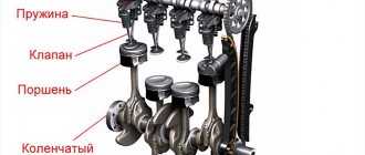
Adjusting valve clearances
If necessary, adjust the clearances in the valve mechanism. We make adjustments on a cooled engine. The gaps can be adjusted using a wide feeler gauge 0.15mm thick, but an adjustment device with a micrometer head is more suitable.
Setting the ignition timing
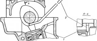
Fig. 1. Shows the location of the marks required to set the correct ignition timing. Front view of the engine (pictured)
We set the ignition according to the instructions. For the VAZ-2106, the moment of opening the contacts in the distributor-breaker, corresponding to the appearance of a spark in the first cylinder, should advance the TDC of the piston stroke of the first cylinder by approximately 0±1°.
Setting the fuel level
So:
Rice. 2. Set the fuel level
- The fuel level of the float chamber affects the composition of the carburetor mixture under any operating conditions, fuel consumption, operating dynamics and exhaust toxicity.
- If necessary, we remove it, disassemble it (see above), and clean the carburetor. When unscrewing the screws responsible for the quality of the mixture and the quantity of the mixture, we remember the number of revolutions by which they were initially from the state of complete closure.
- We wash the jets with a solvent, acetone, for example. To clean the nozzle holes, it is allowed to use a hard brush or a wooden splinter; it is prohibited to use metal wire.
- After washing the jets and channels, they are purged with compressed air using a tire pump or compressor.
- Before starting assembly, be sure to monitor the fuel level of the float chamber. We install the carburetor cover vertically so that the float tongue touches the needle ball lightly, using a gauge we check the gap between the bottom of the float and the plane of the cover (taking into account the cardboard gasket), it should be 6.5 ± 0.25 mm.
- If necessary, the gap is adjusted by bending the tongue on the float. If you do not have the required caliber, use a drill of a suitable diameter.
- We control the stroke of the float, it should ideally be 8±0.25mm. Float stroke